Alpine Ski
Alpine Ski (set 1) (Taito Corporation, 1982) · Manual · 48 pages · 18 sections · original scan
This page carries no recoverable text. It is a drawing or a photograph. See the original scan.
“ALPINE SKI’™ UPRIGHT
ILLUSTRATIONS AND PART LISTS (Cont.) TABLE OF CONTENTS
“ALPINE SKI’™ UPRIGHT GAME SET-UP.......... Page 2
A. Introduction ©... 0... e cece cece eee eee 2 Figure 13 B. Game Inspection ..............:e cece ee eeee eee eee 2 Figure 14 C. Game Installation... 0.00.0... ccc cece 2 Figure 15
D. Dip Switch and Volume Control Settings . Figure 16
MAINTENANCE ... Figure 18
AL Cleaning .......... 2... imctenn center tsmetetasieeense 3 Figure 19 B. Fuse Replacement .............-0.0.000cee eee ee eee 3 Figure 20 C. Video Monitor Removal .........000ccccvveeeeeeeees 3° Figure 21
D. Video Monitor Adjustments (Separate Manual) .......... 4 Figure 22
E. Cover Glass Removal ............-0.0..00000 8 24 Figure 23 F. Printed Circuit Board Replacement ..................- 4 Figure 24
ILLUSTRATIONS AND PART LISTS Figure 26
Figure 1 Option Switches .......0.cscecceseeee 3 Figure 27
Figure 2 Volume Controt Locations 3 Figure 28
Figure 3 Fuse Replacement .........-.......0eeesee eee 6 Figure 29 Figure 4 Video Monitor Removal ..........0cccevteveees 8 Figure 30
Figure 5 -Cover Glass Removal ................005- a) Figure 31
Figure 6 Printed Circuit Board Replacement ....... -- 10 Figure 32
Figure 7 Incandescent Panel...... 12 Figure 33
Figure 8 4-Way Joystick .................eee eee 14 Figure 34 Figure 9 Control Panel ...............ec eee ee eens AS Figure 35 Figure 10 Door Assembly ..............0esc eee e cesses 16 Figure 36 Figure 11 Coin Door... . 2.0.06... cece eee eee e tenes 18 Figure 37
Figure 12 Coin Door... Cabinet Assembly Upright Front View ........... 21
Cabinet Assembly Upright Rear View ........... 22
Filter Board... 2.000... eee eee eee eee 23 Power Supply .
ROM Board... .. 2... 6. eee cece e cece eee eee 25 CPU Board «2.2... e eee eee eee 24 Video Board .... 22.2.2... cece eee 26 Game Board 2.2.0.0... ccc cece eee eee ee 28 Power Supply Schematic 1 of 1 ..
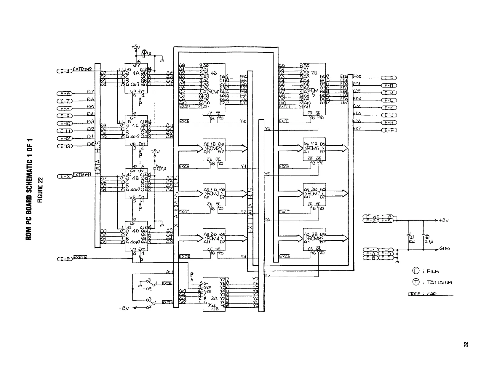
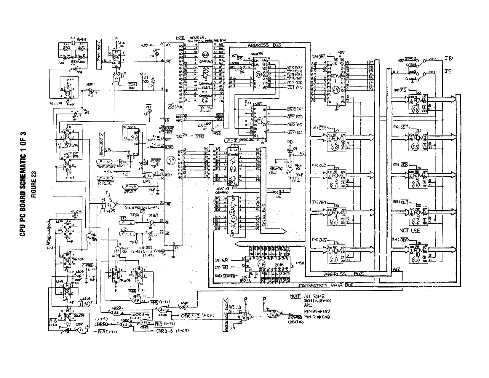
ROM PC Board Schematic 1 of 1. .............. 32 CPU PC Board Schematic 1 of 3..............4 33
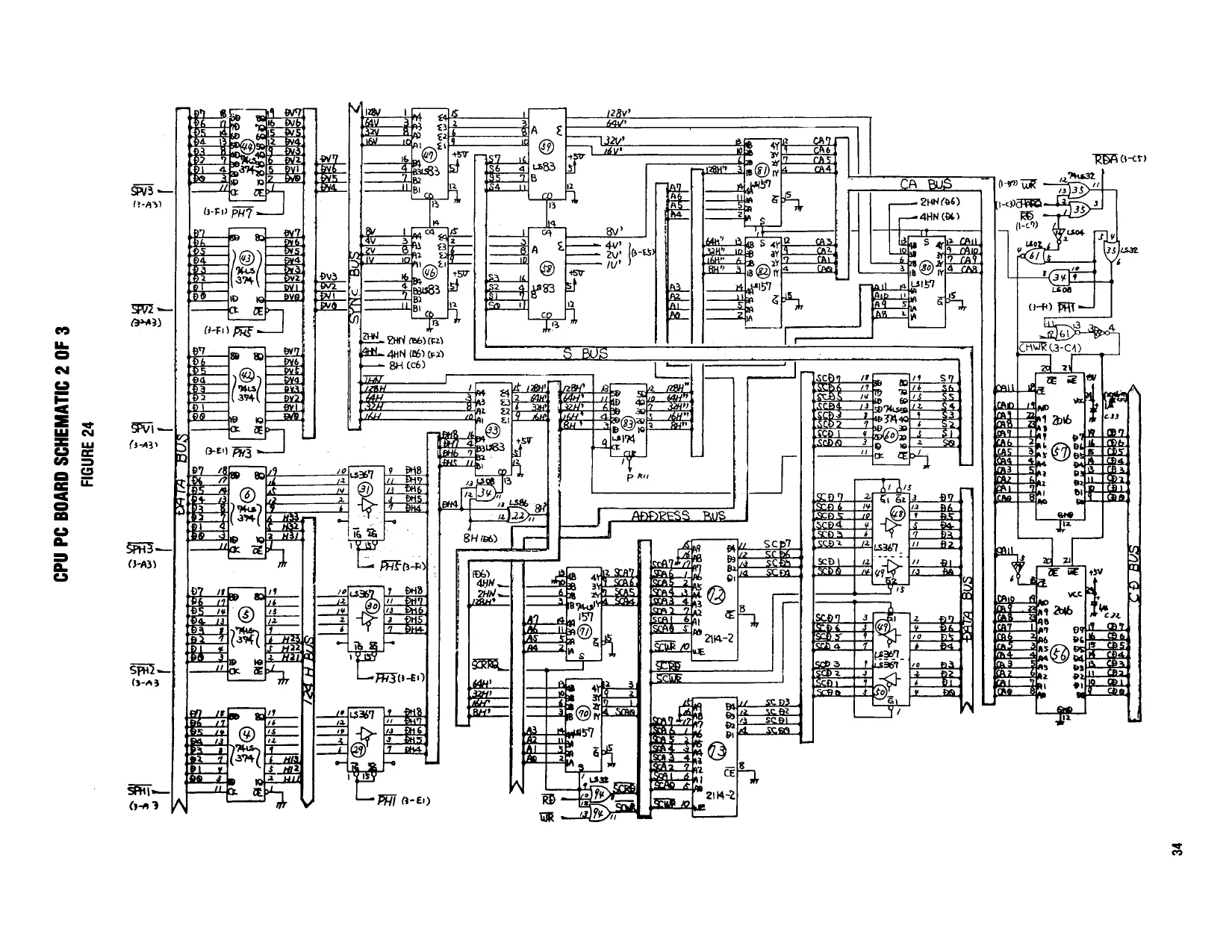
CPU PC Board Schematic 2 of 3..............+ 34
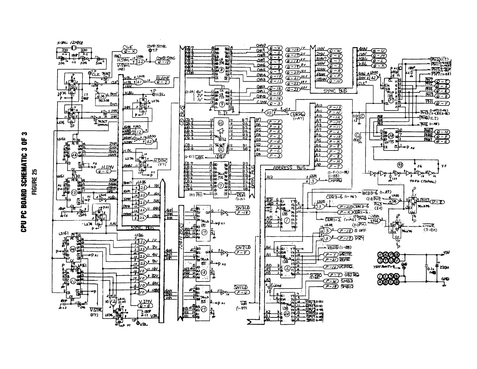
CPU PC Board Schematic 3 of 3...........-.-4 35
Video PC Board Schematic 1 of 5 .
Video PC Board Schematic 2 of 5............. 4 37 Video PC Board Schematic 3 of 5............. 4 38 Video PC Board Schematic 4 of 5........ 2 89
Video PC Board Schematic 5 of 5.............+ 40
Game PC Board Schematic 1 of 6.............+ 41
Game PC Board Schematic 2 of 6
Game PC Board Schematic 3 of 6............. 43
Game PC Board Schematic 4 of 6.............. 44
Game PC Board Schematic 5 of 6............. 45
Game PC Board Schematic 6 of 6.............. 46
Wiring Diagram
“ALPINE SKI’™ UPRIGHT
- GAME SET-UP
A. INTRODUCTION
“ALPINE SKI""™ In Alpine Ski the real enjoyment of skiing is presented by lifelike Down Hill Skiing, Slalom Racing and Ski Jump Competition. The object of the game is to manuever your Skier around snow Mobiles, beginning skiers, etc., skillfully enough to gain the highest amount of points and to go on to the Slalom Course and the Jump Competition. The speed of the Skier can be controlled by depressing the Button. Skiing down the slope successfully allows a Player the chance to challenge the Slalom Course. Be careful not to knock down any poles or you will receive a penalty. Completion of the Slalom Course allows your ‘Skier to go on to the Ski Jump. In the Jump Competition, use the Radar found on the upper portion of the screen to maximize the distance of the jump for Bonus Points. Playing time is increased when the Player reaches the specified Bonus Level.
B. GAME INSPECTION
TAITO AMERICA’S CORPORATION'S “ALPINE SKI”’™ upright game is ready to play when received. However, careful inspection is necessary to insure your game is in perfect condition. Please verify the following before turning the game on.
Examine external parts for chips, dents, or broken parts.
- Open the service door and examine the following:
- Plug-in connectors to make sure they are firmly seated.
- Speaker
- Player Controls
- Printed Circuit Boards making sure there is no damage to the components. Check for loose foreign objects, especially metal objects which may cause electrical problems. Fuses, making sure they are firmly in the holders.
- Coin Mechanisms
The Video Monitor is properly adjusted before shipping. If there are any adjustments necessary refer to our Video Monitor Manual (72-00016- 001).
if problems occur or technical assistance is required, contact our Customer Service Department HOT LINE Toll Free 800-323-0666 (except Iinois). Illinois phone 312 981-1000 X215.
POWER REQUIREMENTS
TAITO AMERICA CORPORATION'S ‘‘ALPINE SkI’""™ upright game is shipped ready for operation at 120VAC, 60Hz with a power consumption of approximately 250 Watts.
For safe operation it is recommended the cabinet be grounded. This game is equipped with a three conductor power cable. The third conductor is the ground conductor and when the cable is plugged into an appropriate receptable, the game is grounded. The offset pin on the power cable's three-prong connector is the ground connection.
LOCATION SPACE REQUIREMENTS
Depth - 35” (87.5cm) Width - 24” (61cm) Height - 68” (171cm) Weight - 300 Ibs. (Packaged Weight) C. GAME INSTALLATION
The following precautions should be followed when installing the game.
- Avoid rough handling of the game, the picture tube is fragile. Install the game on a level surface. Avoid installing the game where it may receive excessive sunlight or heat, to prevent the game from rising internal temperature.
- Do not install in a damp or dusty location. For a short time after connecting the power to the game, the picture may be temporarily distorted
D. DIP SWITCH AND VOLUME CONTROL SETTINGS
Dip Switch A
500-1500 | ON [ON | 800-2000 [OFF[ON | 7000-2500 | ON Bonus Points for Successful Jump
Game Time (Minutes)
[Normal _| 1P Side 2P. Table Upright Screen Inversion
Game Style
Dip Switch B
Play Pricing
1 Coin - 5 Play
1 Coin- 6 Play | OFF 1 Coin - 7 Play
1 Coin - 8 Play 2 Coin - 1 Play OFF
4 Coin - 1 Play ON
5 Coin - 1 Play OFF 6 Coin - 1 Play
7 Coin - 1 Play 8 Coin - 1 Play
9 Coin - 1 Play
Dip Switch C
Points to qualify | 10,000 pts. [For first game _ | 15,000 pts. | Time extension 25,000 pts. Points to qualify | 5,000 pts.
11,000 pts. 12,000 pts. Display of Year [No |
OPTION SWITCHES
SWA
Swc
VOLUME CONTROL SETTING The Volume increases by turning the potentiometer as indicated in Figure 2.
- MAINTENANCE All games require a certain amount of maintenance to keep them in good condition. A periodic check of mechanical controls would be beneficial to guarantee your game will be profitable.
A. CLEANING The exterior of the game, all metal parts and all plastic parts can be cleaned with an non-abrasive cleanser. Caution should be used when Cleaning the plastic, a dry cloth can cause scratches and result in a foggy appearance. B. FUSE REPLACEMENT This game contains 8 fuses. Seven of these fuses can be found on the Power Supply Assembly, five (5) are on the PCB and two (2) are on the Power Supply Bracket. One (1) is located at the bracket where the AC line cord comes into the cabinet. See Figure ( ) for location of these fuses.
FUSE REPLACEMENT
C. VIDEO MONITOR REMOVAL 4f you need to remove the Video Monitor, follow the Instructions listed below.
It is recommended the game be left disconnected for at least one hour before removing the Video Monitor. This will probably discharge the Video Tube but EXTREME
Disconnect power from the line voltage. Disconnect the Monitor cable connector. Remove the wire cable clamp. Take out the two side bolts, one on each side of the cabinet. Remove the four mounting bolts and disconnect the green ground wire.
- Slide the Monitor out by pulling the Monitor toward you.
Use extreme caution and do not touch electrical parts of the Monitor Yoke area with your hands or with any metal object in your hands! High voltages may exist in any Monitor, even with power disconnected.
MONITOR REMOVAL
D. VIDEO MONITOR ADJUSTMENTS
TAITO AMERICA CORPORATION presently uses either a Wells- Gardner or an Electrohome 19” color monitor in the “ALPINE SKI"™ game. Refer to Monitor Manual (72-00016-001) for your specific Video Monitor. Be sure to heed all the WARNINGS AND CAUTION INSTRUC- TIONS provided before repairing or replacing your Video Monitor.
E. COVER GLASS REMOVAL
To remove the Cover Glass follow the Instructions listed below:
- Remove the control Panel
- Loosen three (3) screws on the Cover Glass, front bracket.
- Open Service Door and remove the (Rear) Cover Glass Bracket.
- Slide glass out through the Service Door.
COVER GLASS REMOVAL F. PRINTED CIRCUIT BOARD REPLACEMENT
You may wish to remove the “ALPINE SKI"™ Printed Circuit Boards for servicing. Refer to Figure 6. The “ALPINE SKI" Printed Circuit Boards are located on the inside of the Rear Service Door for easy access. To remove the boards the following steps should be followed:
- Open the rear service door, the power will automatically be removed by the Interlock Switch located on the inside of the door frame
- Disconnect the connector G, H, and T from the boards.
- Loosen and turn the Stop Bracket and pull the boards toward you out of the board guides.
PRINTED CIRCUIT BOARD REPLACEMENT
INCANDESCENT PANEL
TAITO ITEM PART NO. DESCRIPTION 1 27-00006-001 | Lamp #47 2 26800009-001 | Bayonet Base Socket 3 26B00009-001 | Marquee Lighting Plate
2-WAY JOYSTICK
ITEM TAITO PART NO. DESCRIPTION 63B00071-001 Ball & Shaft 63A00074-001 Mask 63C00069-001 Mounting Plate 62C00004-001 Shock Mount Pad 63¢600070-001 Switch Plate 63A00075-001 Actuator 59B00020-017 “E" Ring 63A00072-001 Switch Spacer 29B00033-001 Leaf Switch 58A00006-001 Spring 61A00227-001 Spacer 63A00073-001 Spacer, Plastic
CONTROL PANEL
TAITO ITEM PART NO. DESCRIPTION 1 63B00031-004 }Ball & Shaft 2 63800024-001 {Push Button White 3 63-00025-001 | Switch Support 4 29800020-001 | Switch, Push Button 5 54A07001-008 jNut, Stamped 58-11 6 63D00067-001 |2-Way Control 7 42B00108-001 |Cleate Wood 8 42000017-001 Control Panel Wood [3 63D00066-001 }Lexan Decal 10 07M00224-001 |Control Panel, Metal
DOOR ASSEMBLY
TAITO PART NO. DESCRIPTION 42D00128-001 Rear Door 61A00111-004 Bracket, Lock Rod 04-00037-002 Lock Kit 08-00017-001 Filter P.C.B. 63B00077-001 Board Guide 61A00014-001 “LY Bracket
08-00028-002 Game P.C.B. 08-00028-003 CPU P.C.B. 08-00028-004 Video P.C.B. 08-00028-005 ROM P.C.B. 61-00228-001 Bracket, P.C. Board
DOOR ASSEMBLY
COIN DOOR
TAITO
| ITEM | PART NO. | DESCRIPTION | REFERENCE |
| 1 | 07-00027-001 | Inner Panel With Levers Sub Assembly | 404429 | |
| 2 | 54-03013-001 | Nut #8-32 | 400-8 |
7 09-00017-001 | Custom Harness Assembly (SHL Coin)
- 09-00017-002 | Custom Harness Assembly (Dual Coin) 3 61B00113-001| Service Switch Bracket 4 29-00022-001 | Service Switch 5 54-03011-001 | Nut #4-40
| 6 | 63-00014-001 | Switch Cover | 904762 | |||
| 7 | 51-02052-001 | Screw #6-32 x °/o SS ph | 100-6-3 | |||
| 8 | 23-00001-001 | C.R.E.M. Coil Assembly | 404354 | |||
| 9 | 51-02052-001 | Screw #6-32 x “/1e SS ph | 100-4-12 | |||
| 10 | 59-00019-001 | Retainer | 900651 | |||
| W | 28-00029-001 | Silver Switch Wire for U.S. 25¢ | 904710-1 | |||
| 12 | 29-00007-001 | Switch | 904845 | |||
| 3 | 61-00044-001 | Coin Chute | _ | 7 | 904701 | |
| 14 | 61-00045-001 | Coin Return Box | a | 904598 | ||
| 15 | 61-00025-001 | Switch & C.R.E.M. Coil Bracket | oO _ | ___ | [404428 | |
| 16 | 59-00018-001 | 25¢ Acceptor | oo | - | __| | 5301-10 |
7 51-02051-006 | Screw 4-40 x % SS ph — __ [110-46
| 18 | 27-00003-001 | Miniature Bayonet Base Lamp | 904717 |
26-00006-001 | Lamp Socket _
| 19 | 27-00003-001 | #47 Lamp (6.3 Volt) | 904716 |
| 20 | 61-00048-001 | Coin Inlet Chute | 904418 |
| 21 | 61-00047-001 | Right Half of Coin Inlet Chute | 904594 |
| 22 | 54-00001-001 | ‘‘U" Type Fastener | 904712 |
| 23 | 51-02051-006 | Screw 4-40 x ¥ SS ph | 116-4-8 |
| 24 | 29-00006-001 | Slam Switch Assembly | 904704 |
25 998325 Coin Meters
*ltem not shown on drawing.
COIN DOOR
COIN DOOR
TAITO
| ITEM | PART NO. | DESCRIPTION | REFERENCE | |
| 1 | 61-00042-001 | Coin Door Only (2 Coin) | - | 404341 | |
| 2 | 07-00023-001 | Coin Return Button Assembly For U.S. 25¢ Coin | ~ | 404348-1 | |
| 3 | 63-00015-001 | Coin Return Button | 904591 | ||
| 4 | 79-50004-001 | U.S. 25¢ Price Decal | 904703 | ||
| 5 | 63-00016-001 | Coin Return Button Cover for U.S. 25¢ Coin | ~ | ||
| 6 | 07-00025-001 | Lock Assembly | - | 904707-1 | |
| 6A | 07-00025-001 | Lock Assembly | 904707-1 | ||
| 7 | 51-01051-003 | Screw #4 x */1« SL ph Type B | | | 345-45 | |
| 7A | 51-01051-003 | Screw #4 x S/1 SL ph Type B | - | 7 | 345-4-5 |
| 8 | 63-00011-001 | Coin Button Housing | ~ | 904588 | |
| 9 | 51-02051-002 | Screw #4-40 x 4 SL ph | 325-4-4 | ||
| 10 | 63-00012-001 | Coin Return Bezel | 904590 | ||
| "i | 63-00013-001 | Coin Return Cover | 904599 | ||
| 12 | 61-00040-001 | Coin Door Frame 11% x 13% | 904581 |
Mounts in a 10% x 12%/16 Opening
| 13 | 54-01005-001 | Hex Nut %-20 | 406-416 |
| 14 | 51A03003-113 | Carriage Bolt | 904734 |
| 15 | 07-00026-001 | Lock Arm Assembly | 404357 |
COIN DOOR
CABINET ASSEMBLY UPRIGHT FRONT VIEW
TAITO EM | PART NO. DESCRIPTION 1 _|07M00055-001 | Incandescent Panel 2 63B00006-001 |‘'U" Channel Bracket 3 47M00012-004] Marquee 4 61C00115-001 | Marquee Retaining Bracket 5 61D00012-001 | Lower Cover Glass Bracket 6 07M00121-001} Control Panel Assembly 7 07-00114-001 Tccin Door 8 ~ [61800113-007 | Switch Bracket 9 07M00118-001| Service Switch Assembly 10 29-00022-001 | Slide, Center Return Switch 11 29B00015-001 | Interlock Switch 12 __|61000201-001 | Interlock Switch Bracket 13 59-00008-001 | Latching Clamp 14 63B00002-004 | ‘‘T"’ Molding, 15 29A00023-001 | Power ON/OFF Switch 16 410D00009-004 | Finish Cabinet
CABINET ASSEMBLY UPRIGHT FRONT VIEW
CABINET ASSEMBLY UPRIGHT REAR VIEW
TAITO
| ITEM | PART NO. | DESCRIPTION |
1 42D00069-001 | Door & Board Mounting Assembly 2 42000016-001 | Door Panel 3 21C00003-001 | Speaker 6” round 4 61B00027-001 | Speaker Grill | 5 41D00009-004 | Finish Cabinet 6 61B00057-001 | Leaf Hinge 7 61C00006-001 | Upper Cover Bracket 8 63C00035-001 | Monitor Shroud 9 61C00080-001 | Monitor Mounting Bracket 10 27-00006-001 | #47 Bulb, Lighted Instr. i} 47M00013-004 | Cover Glass 12 44C00001-001 | Wheels 13 63C00005-004 | ‘Leaf’ Molding 14 07M00042-001 | A/C Line Cord 15 63C00005-022 |‘L’’ Molding 16 61B00030-002 | Interlock Bracket 17 29B00015-001 | Interlock Switch 18 07M00039-001 | Power Supply 61000054-001 |Cash Box Lid 61B00056-001 | Leaf Hinge 61A00055-001 |Hinge Pin 31-00006-001 19” Color Monitor 63-00019-001 Cash Tray Separator 61-00039-001 Cash Tray Handle 61C00060-001 Cash Box [63-00010-001 Cash Tray (Only) [o7mo0054-001 Cash Tray Assembly 42C00013-001 Monitor Support Cleat 29 61C00086-001 |Corner Bracket
| 30 | 08-00028-002 | |Game P.C.B. |
| 31 | 60B00142-001 | {Lock Rod Assembly |
| 32 | 08-00028-004 | |Video P.C.B. |
33 04M00037-002 |Lock Kit
| 34 | 08-00028-003 | |CPU P.C.B. |
| 35 | 08-00028-005 | [ROM P.C.B. |
08-00017-001 [Fiter P.C.B. ps
CABINET ASSEMBLY UPRIGHT REAR VIEW
FILTER BOARD
TAITO PART NO. DESCRIPTION QUANITY 12-10003-471 | Cap, 470pf + 10% Axial Lead 74 17-00001-001 | Ferrite Bead Assembly 42 25-00002-014 | Connector 14P 9 25-00002-005 | Connector SP 2 14-23904-001 | Transistor NPN 2N3904 1 11-00001-102 | Resistor 1K ohm YW 1 11-00001-332 | Resistor 3.3F ohm YW 2 63B00068-001 | Stand Off 6
= 7 = _| L-S-conn, 5 Pn
s&s .
9g
sje BEADS
| : | ° | : | ° | : | ai |
RESISTOR ft resistor S
= a | -conn 14P
| ee | oa | < |
PACITOR
| S | a | Fmssron |
he
POWER SUPPLY
TAITO TAITO SYM | PART NO. DESCRIPTION SYM | PART NO. DESCRIPTION R1 | 11-00001-102 | Resistor 1.0K 5% YW 5% C5 | 12-10001-102 | Capacitor, O01uf
| R2__| | 11-00001-512 | Resistor 5.1K YW 5% | C6 | 12-30001-106 | Capacitor, Tantalum 10uf |
| R3_| | 11-00001-183 | Resistor 18K ¥W 5% | C7 _| 12-20003-509 | Capacitor, Electrolytic 50,000uf |
R4 | 11-00001-224 | Resistor 220K %4W 5% C8 =| 12-30001-105 | Capacitor, Tantalum 1.uf 35V R5 | 11-00001-472 | Resistor 4.7K %W 5% C9 | 12-20003-209 | Capacitor, Electrolytic 20,000uf R6 | 11-00001-222 | Resistor 2.2K VW 5% C10 | 12-10001-332 | Capacitor, Ceramic .0033uf
| R7__| | 11-10001-101 | Resistor 100 YW 5% | C11 | 12-30001-476 | Capacitor, Tantalum 47uf |
R8 | 11-00001-102 | Resistor 10K t4W 5% C12 | 12-30001-105 | Capacitor, Tantalum 1.uf 35V RQ | 11-00001-472 | Resistor 4.7K VaW 5% C13 | 12-10004-103 | Capacitor, Ceramic .O1uf R10 | 11-10001-101 | Resistor 100 Y2W 5% C14 | 12-10001-102 | Capacitor, .0Otuf R11 | 11-30001-015 | Resistor 15 4W 5% C15 | 12-30001-476 | Capacitor, Tantalum 47uf Ri2 | 11-30001-015 | Resistor .15 4W 5% C16 | 12-20002-108 | Capacitor, Electrolytic 1,000uf R13 | 11-00001-472 | Resistor 4.7K %4W 5% C17 | 12-30001-225 | Capacitor, Tantalum 2.2uf 25V R14 | 11-00001-222 | Resistor 2.2K YW 5% C18 | 12-30001-225 | Capacitor, Tantalum 2.2uf 25V R15 | 11-00001-222 | Resistor 2.2K %4W 5% C19 | 12-30001-105 | Capacitor, Tantalum 1.uf 35V R16 | 11-60001-252 | Pot 2.5K YaW 20% F1 | 24-00003-010 |10A Fuse
| | R17 | 11-00001-222 | Resistor 2.2K %4W 5% | F2 | 24-00003-010 |10A Fuse |
| R18 | 11-60001-102 | Pot 1.0K YW 20% | F3__ | | 24-00003-003 |Fuse, 2A |
| R19 | 11-00001-511 | Resistor 510 %4W 5% | Fa | 24-00003-004 | Fuse, 4A |
| R20 | 11-10001-470 | Resistor 47 YW 5% | F5 | 24-00003-004 |Fuse, 4A |
R21 | 11-00001-162 | Resistor 1.6K %W 5% BR1 | 13-00100-025 | Diode Bridge 25A, 100V R22 | 11-00001-103 | Resistor 10K ¥%W 5% BR2 | 13-00100-012 | Diode Bridge 12A, 100V R23 | 11-00001-472 | Resistor 4.7K YaW 34 BRS | 13-00100-002 | Diode Bridge 2A, 100V R24 | 11-00001-222 | Resistor 2.2K YaW 5% _ D1 | 13-14002-001 | Diode IN4002 R25_ | 11-60001-102 | Pot 1.0K %W 5% D2 | 13-14002-001 | Diode IN4002
| R26 | 11-00001-472 | Resistor 407K YW 5% | D3_| | 13-10752-001 | Diode, Zener IN752 |
R27 | 11-00001-222 | Resistor 2.2K YW 5% D4 | 13-14002-001 | Diode IN4002 R28 | 11-60001-252 | Pot 2.5K YW 20% DS | 13-14002-001 | Diode IN4002 R29 | 11-00001-472 | Resistor 4.7K Y4W 5% D6 | 13-14002-001 | Diode IN4002 R30 | 11-00001-122 | Resistor 1.2K %4W 5% D7 | 13-10964-001 | Diode, Zener IN964 R31 | 11-10001-470 | Resistor 47 VW 5% D8 | 13-14002-001 | Diode IN4002
| R32_| | 11-30001-015 | Resistor .15 4W 5% | D9 | 13-14002-001 | Diode IN4002 |
| R33_| | 11-00001-222 | Resistor 2.2K YW 5% | D10 | 13-14002-001 | Diode IN4002 |
R34 | 11-00001-122 | Resistor 1.2K YaW 5% D11_ | 13-14002-001 | Diode IN4002 R35 | 11-00001-511 | Resistor 510 Y4W 5% D412 | 13-14002-001 | Diode IN4002 R36 |11-00001-222 Resistor 2.2K ¥W 5% LED1] 13-00001-001 | LED (Red) R37 | 11-00001-104 | Resistor 100K LED2] 13-00001-001 | LED (Red) R38 | 11-00001-103 | Resistor 10K %4W 5% LED3} 13-00001-001 | LED (Red) R39 | 11-00001-224 | Resistor 220L V4W 5% LED4| 13-00001-001 | LED (Red) C1 | 12-30001-225 | Capacitor, Tantalum 2.2uf 25V Ut | 15-62500-001 | Opto Coupler H11AA2 C2 | 12-10004-103 | Capacitor, Ceramic .O1ut U2 | 15-50556-001 | Timer (Dual) 556 C3 | 12-10004-103 | Capacitor, Ceramic .O1uf U3 | 15-50723-001 | Voltage Regulator 723 C4 | 12-30001-105 | Capacitor, Tantalum 1.uf 35V U4 | 15-50723-001 | Voltage Regulator 723
POWER SUPPLY
[s TAITO SYM | PART NO. DESCRIPTION REG1| 15-57912-001 | Voltage Regulator 7912 REG2| 15-57905-001 | Voltage Regulator 79L05 Qi | 14-22905-001 | Transistor 2N2905 Q2 | 14-22905-001 | Transistor 2N2905 Q3__| 14-22905-001 | Transistor 2N2905 Q4 | 14-22905-001 | Transistor 2N2905 Q5 | 14-23055-001 | Transistor 2N3055 Q6 | 14-22905-001 | Transistor 2N2905 Q7__| 14-20030-001 | Transistor TIP-30A Q8 | 14-26401-001 | SCR 2N6401 Q9__| 14-26401-001 | SCR 2N6401 Jt | 25-00022-006 | Connector, 1-380999-0 6Pin J2__ | 25-00022-008 | Connector, 350212-1 8Pin J3 25-00002-014 | Connector, 09-60-1141 14Pin J4 | 25-00002-014 | Connector, 09-60-1140 14Pin 24-10001-001 | Fuse Clips 30-00220-002 | Heat Sink Dual To-220 30-00003-001 | Heat Sink Single To-3
vs
vs
ee) POWER SUPPLY COMPONENT LAYOUT
F i . etm 30mm
Ga, Go, c « Oe sO) a>) facial - + GH a *Q op co 100-20000-80 ie OLIVE
asvs
ral
This page reads as a drawing: its text was drawn rather than typeset, and comes out in fragments. See the original scan.
ROM PC BOARD LAYOUT
ise th rr
Bi - Warro/ ace
This page reads as a drawing: its text was drawn rather than typeset, and comes out in fragments. See the original scan.
This page carries no recoverable text. It is a drawing or a photograph. See the original scan.
This page reads as a drawing: its text was drawn rather than typeset, and comes out in fragments. See the original scan.
fabaahe rrereen ERENT Oh ee be BERBRB HSS BR Ree efegBh: AaSOaSR FAIGGH0 BOABRAA, Jape Sant 88 Q a o = fo
GAME BOARD
| TAITO | T | TAITO |
PART NO. _| DESCRIPTION Tem |SYM | PARTNO. _| DESCRIPTION GAME PCB 49_[ic28 | 99-aaTazo99 | TTL 1c 74367
| 99-AA055103 | IC SOCKET 18P | 60 | _|i¢27 | 99-AATS2003 | TTL IC 7404 | ||
| 99-4A052566. | DIP SWITCH | 61 | [cee | _|99-aaT32011 | [TILic 7474 |
| 99-AA055160 | CONNECTOR PLUG HKP-30M | 52 | _[ic29 | 99-aaTs2161 | TIL IC 7427 |
99-AA055169 | 1G SOCKET 28P 53__|ROM | 99-RHO9041S | PROM (2732) RH-13
| 99-AA055310 [ANGLE PIN HEADER PS-50PA | 64 | [C1 | __[99-AAT41019 | CAP, ELECTROLYTIC 16VB220 MF | ||
| 99-AA055787 | IC SOCKET 24° | 55 | |c2 | | 99-AAT41023 | CAP, ELECTROLYTIC 16VB220 | ||
| 99-AA055812 | [IC SOCKET 40P | 56 | [C3 | ___|99-AAT41238 | CAP, FILM TDY-1M-103 | |
| “[99-AA055000 | [IC SOCKET 22P | 57 | [C4 | | 99-AAT41740 | CAP, FILM TDY-1H-223 | |
| ~_[99-aaosesst | [TEST POINT | 58 | [C5 | __|99-AAT41244 | CAP, FILM TDY-1H-104 | |
| 99-AA060557_| | LOCKING CIRCUIT BOARD SUPPORT| | 59 | [C6 | | 99-AAT41310 | [CAP, CERAMIC 47PF 50V |
| 99-AAT11040_| | TRANSISTOR 254423 | 60 | NOT USED | ||
| PAN HO SCREW M3X6 | 61 | [C8 | | 99-AAT41922 | CAP, CERAMIC 150PF SOV |
NUT M3 62_|69___[99-AAT41374 | CAP, CERAMIC 160PF 50V
| {99-AAT11070_| | TRANSISTOR 250635 | 6 | | | NOT USED | |
| PAN HO SCREW | 64 | [C11 | __[99-AAT41394 | CAP, CERAMIC 470PF 50V | ||
| NUT M3 | 65 | [C12 | [99-AAT#1430 | CAP, TANTALUM SSG25-10F | ||
| 99-AAT31011_[OP AMPLIFIER 1M3000 | 66 | [C13 _ | 99-AAT41431 | CAP, TANTALUM SSG35-ORIF | |||
| 99-AAT31050 | [OP AMPLIFIER MR3230 | 67 | [cia | _|99-AAT41436 | [CAP, TANTALUM SSG35-1F |
| PAN HO SCREW M3X8 | 68 | C15 | | 99-AAT41437 | CAP, TANTALUM SSG35 7R2F | ||
| NUT M3 | 69 | Ri | 99-AAT51741 | RES, CARBON 100 OHM 1/2W 5% | ||
| 99-AAT32033._|TTL-IC 7416 | 70_[R2 | | 99-AATS1749 | RES, CARBON 220 OHM 1/4W 5% | |||
| 99-AAT32049_|TTL-IC 7417 | 71__[R3___ | | 99-AAT51751 | RES, CARBON 270 OHM 1/4W 5% | ||
| 99-AATS2163_ | [STATIC RAM 2114.2 | 72__|R4 _ [99-AAT51753 | [RES, CARBON 330 OHM 1/4W 5% | ||
| 99-AAT32165 | [SOUND IC AY38910 | 73 | [Rs | 99-AAT51755 | RES, CARBON 390 OHM 1/4W 5% | |
| 99-AATS2179 | [TTL - RAM 93410 | 74__[R6 | | 99-AATS1757 | RES, CARBON 470 OHM 1/4W 5% | ||
| 99-AAT33001 | |LS-IC 74LS00 | 75 | R7 | 99-AAT51765 | |RES, CARBON 1K |
| 99-AATS3003_|LS-IC 74.802 | 76 | _|R8 | | 99-AAT51779 | |RES, CARBON 396 OHM 1/4W 5% | |
| 99-AAT33005 | |LS-IC 74LS04 | 77 | Ro | 99-AAT51781 | RES, CARBON 47K OHM 1/4W 5% | |
| 99-AAT33009_[LS-I0 741808 | 78 | {R10 _ | 99-AAT51789 | |RES, CARBON 10K OHM 1/4W 5% | ||
| 99-AAT33027_|TI (ONLY) 741837 | 79 | [Rit __ | 99-AAT51796 | RES, CARBON 20K OHM 1/4W 5% | ||
| 99-AATS3051_|LS-I0 74LS74 | 80 | [R12 _ | 99-AATSt797 | [RES, CARBON 22K OHM 1/4W 5% | ||
| 99-AATS3070_|LS-i0 74/896 | 81 | [R13 | | 99-AAT51803 | RES, CARBON 39K OHM 1/4W 5% | ||
| 99-AAT33096_|LS-IC 7418138 | 82 | [Rid | _[99-AAT51775 | |RES, CARBON 2.7K OHM 1/4W 5% | |
| 99-AAT33097 | _|LS-IC 7418139 | 83 | [R15 | [99-AATS1811 | _|RES, CARBON 82K OHM 1/4W 5% |
| 99-AAT33108 | [LS-IC 7418153 | 84 | [R16 _ [99-AAT51617 | RES, CARBON TOOK OHM 1/4W 5% | ||
| 99-AAT33110_[LS-IC 7415185 | @5_[R17__| | 99-AAT51823 | [RES, CARBON 270K OHM 1/4W 6% | ||
| 99-AATS3163_[LS-IC 7418253 | 86 | [R18 | | 99-AATS1825 | [RES, CARBON 330K OHM1/4W 5% | |
| 99-AAT33164_[LS-IC 7418257 | 7 | [R19 _ | 99-AATS1827 | RES, CARBON 390K OHM 1/4W 6% | ||
| 99-AAT33166 | |LS-IC 74/8259 | 88 | [R20 | _|99-AAT51829 | |RES, CARBON 470K OHM 1/4W 5% |
| 99-AAT33170 | |LS-1C 74LS273 | 89 | R21 | 99-AAT51833 | RES, CARBON 680K OHM 1/4W 5°%| | |
| 99-AATS3203_[LS-IC 7418367 | 90 | [R22 _ | 99-AAT51837 | [RES, CARBON 1M OHM 1/4W 5% | ||
| 99-AAT33209_[LS-IC 7418374 | 1 | [R23 _ | 99-aAT51733 | [RES, CARBON 47 OHM 1/4W 5% | ||
| 99-AATS3220_[LS-IC 7418393 | 2 | NOT USED | |||
| 99-AAT34008 | [CPU Z-80A | 93 | [R25 | | 99-AATS1845 | [22M OHM 1/4W 5% |
| 99-AAT36105 | [CMOS MB14584 | 4 | NOT USED | ||
| "[ge-aaT32005 | [CUSTOM IC mB14257 | | | 95 | NOT USED |
GAME BOARD
TAITO PART NO. DESCRIPTION 99-AAT51068 |15K OHM 1/4W 5% 99-AAT51969 [30K OHM 1/4W 5% 99-AATS1971. | 1M 1/4W 5% 99-AAT51982 |RES, CARBON 1 OHM 1/2W 5%. 99-AAT53041_| VARIABLE RESISTOR 8-50K 99-AAT55036 |RESISTOR BLOCK 1K OHM 8 ELEMENTS 99-AATS5061 | RESISTOR BLOCK 10K 100 OHM 8} ELEMENTS 99-AAT12009 | DIODE VO3C 99-AAT13025 | ZENER DIODE RD4.2EC
| 105 | |Z02 | 99-AAT13026 | ZENER DIODE RDS.6EB | |
| 106 | |2D3 | 99-AAT13028 |ZENER DIODE RD9A-M | |
| 107 | _|ST1 | 99-EE070004 |HARNESS STICKER | |
| 108 | |ST2 | 99-RHO70201 | PCB STICKER RHNOO001 | | |
Aaa | i So
POWER SUPPLY SCHEMATIC 1 OF 1
a
This page is a drawing, shown as the original scan.
This page is a drawing, shown as the original scan.
This page is a drawing, shown as the original scan.
This page is a drawing, shown as the original scan.
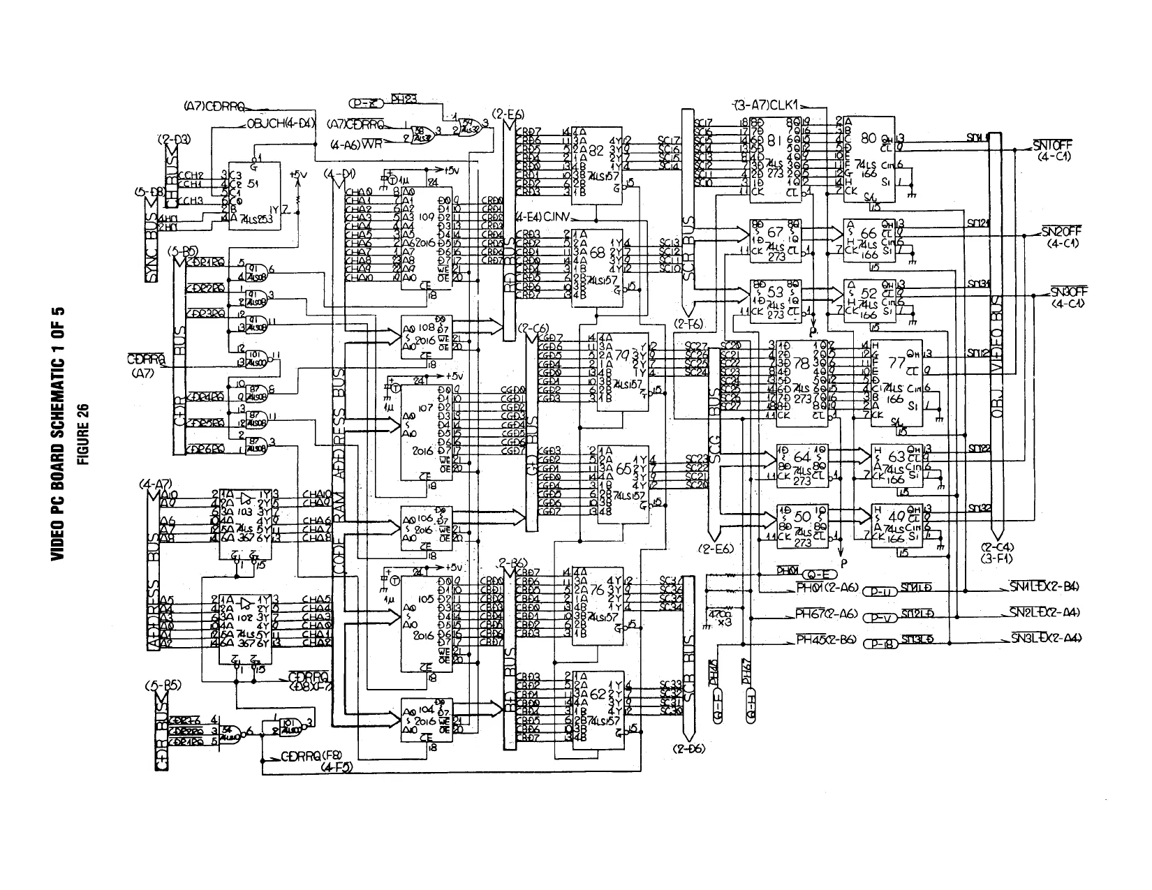
This page is a drawing, shown as the original scan.
This page reads as a drawing: its text was drawn rather than typeset, and comes out in fragments. See the original scan.
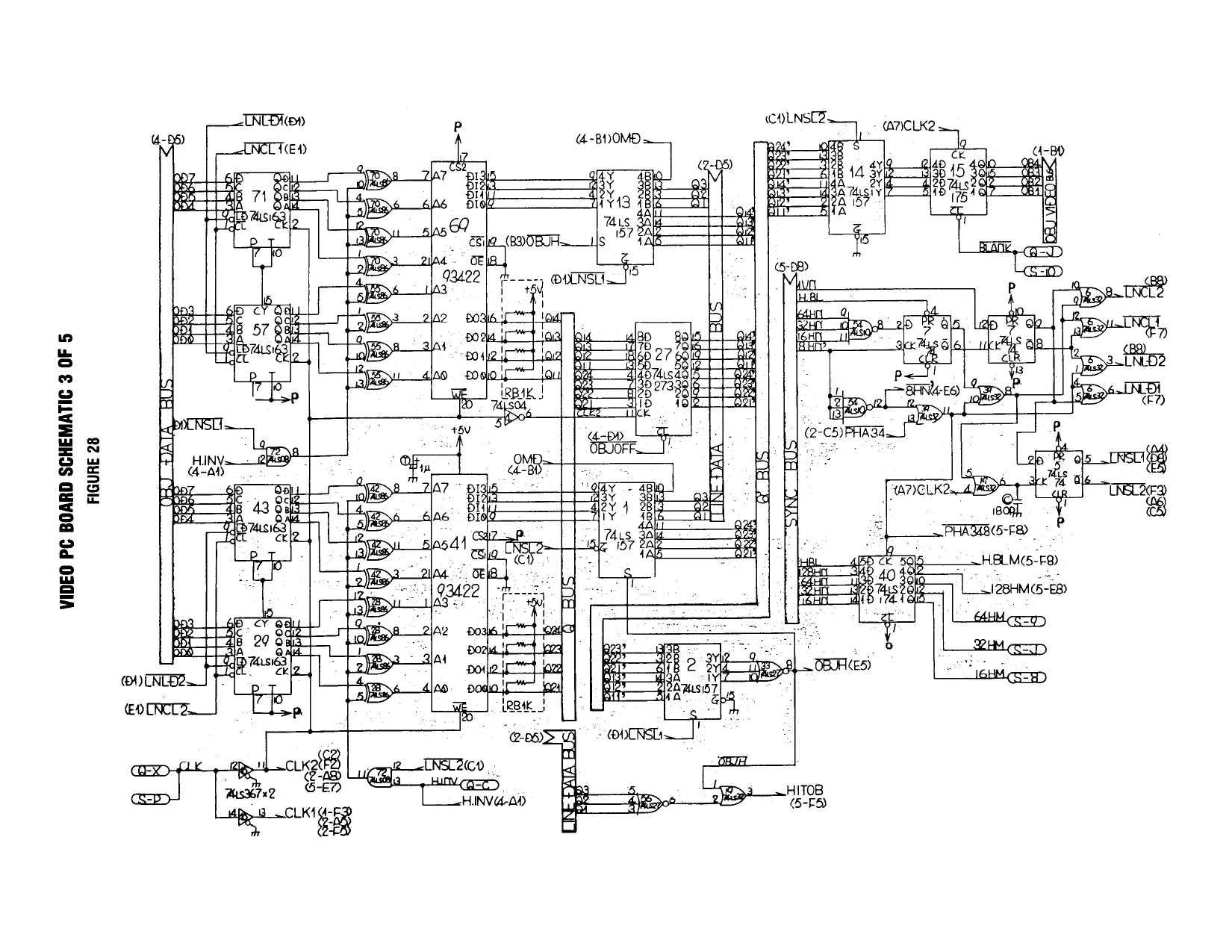
This page is a drawing, shown as the original scan.
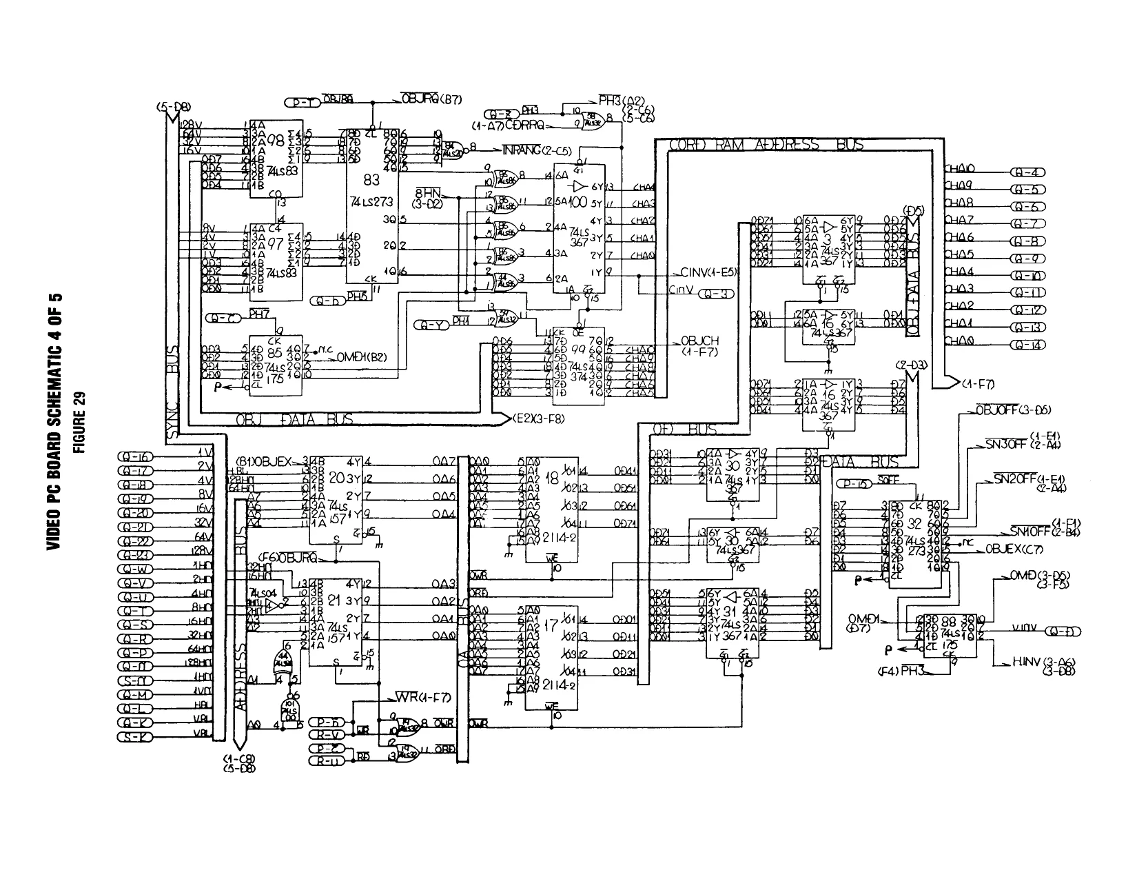
This page is a drawing, shown as the original scan.
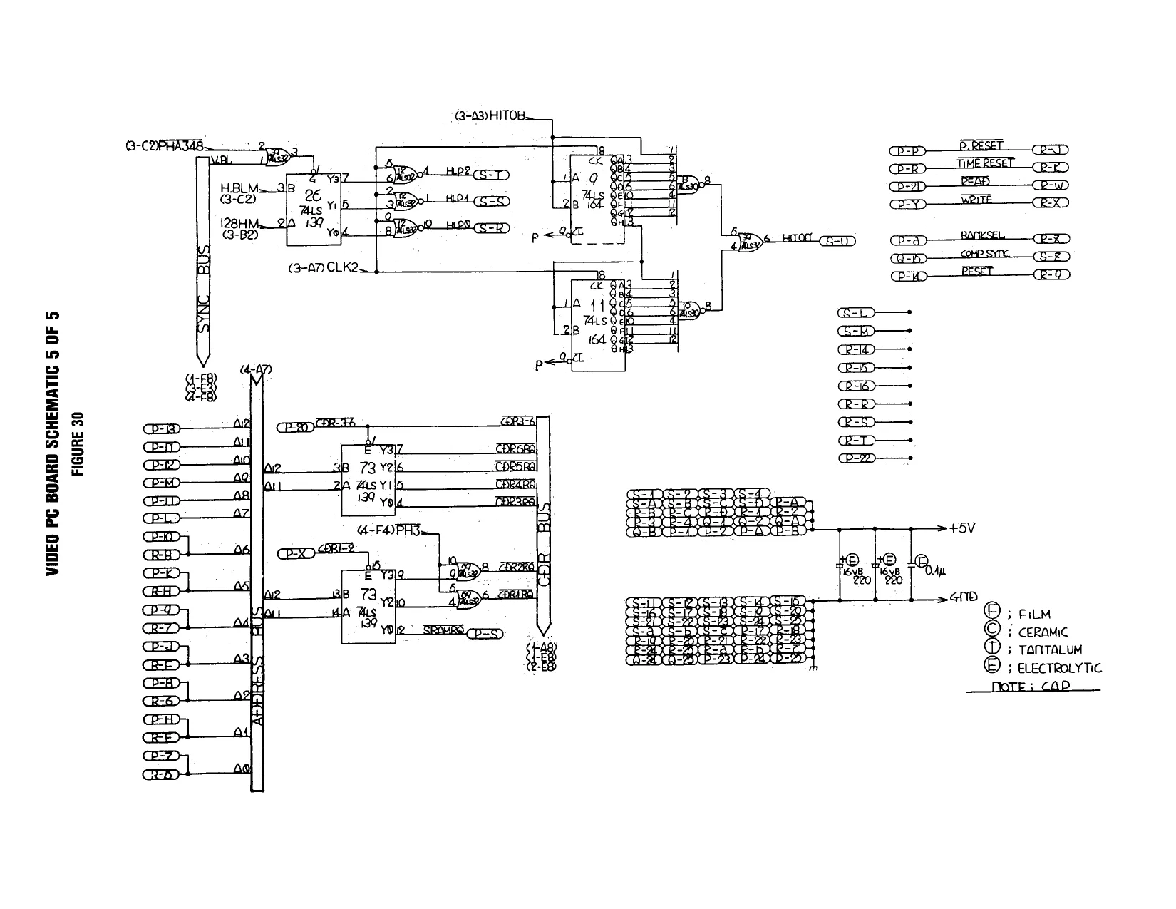
This page is a drawing, shown as the original scan.
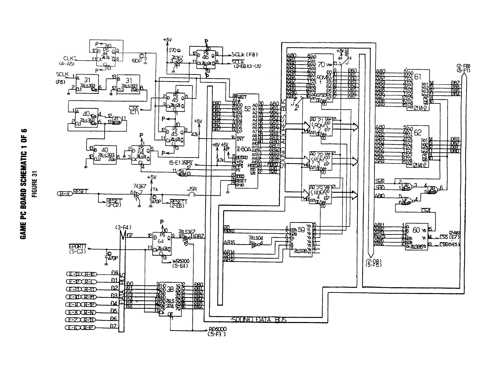
This page is a drawing, shown as the original scan.
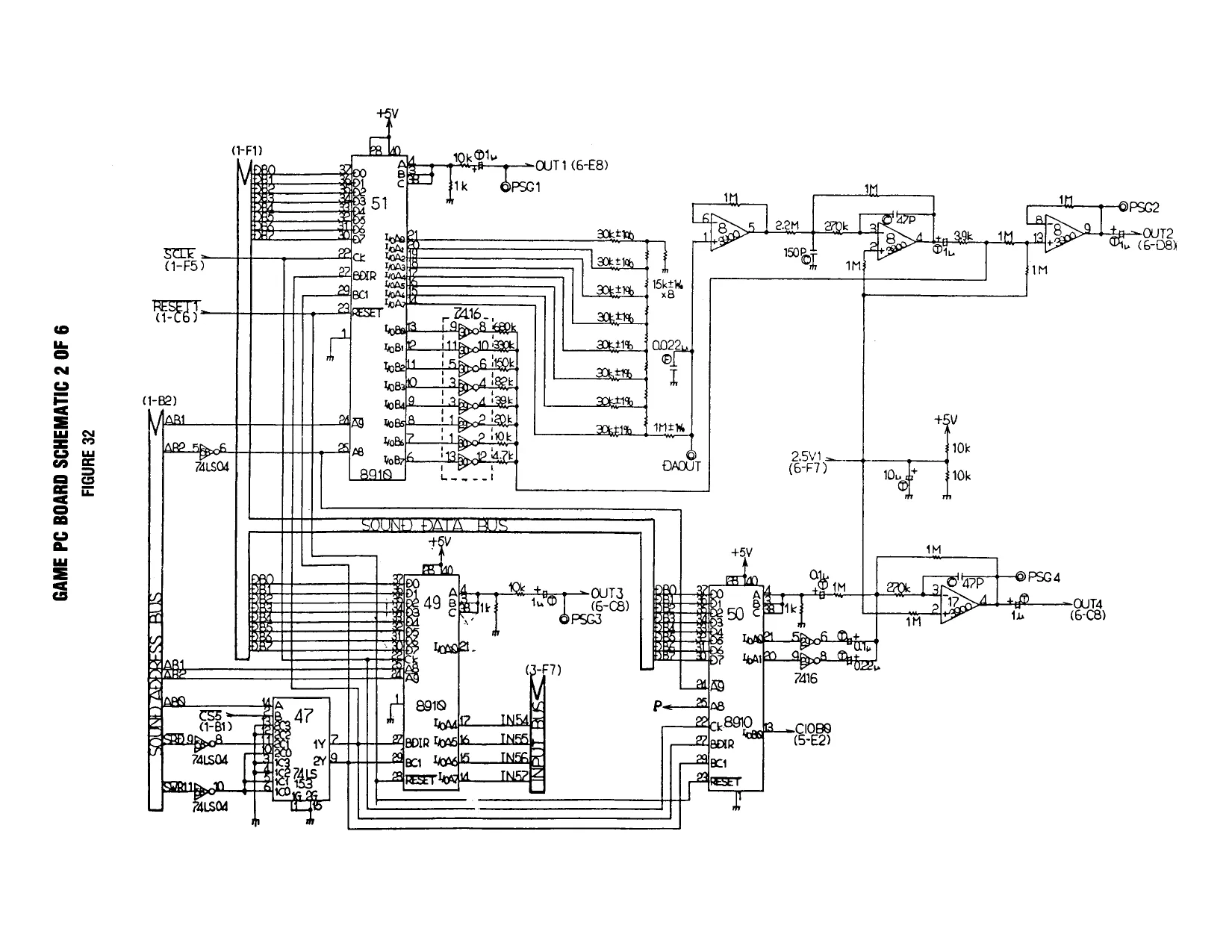
This page is a drawing, shown as the original scan.
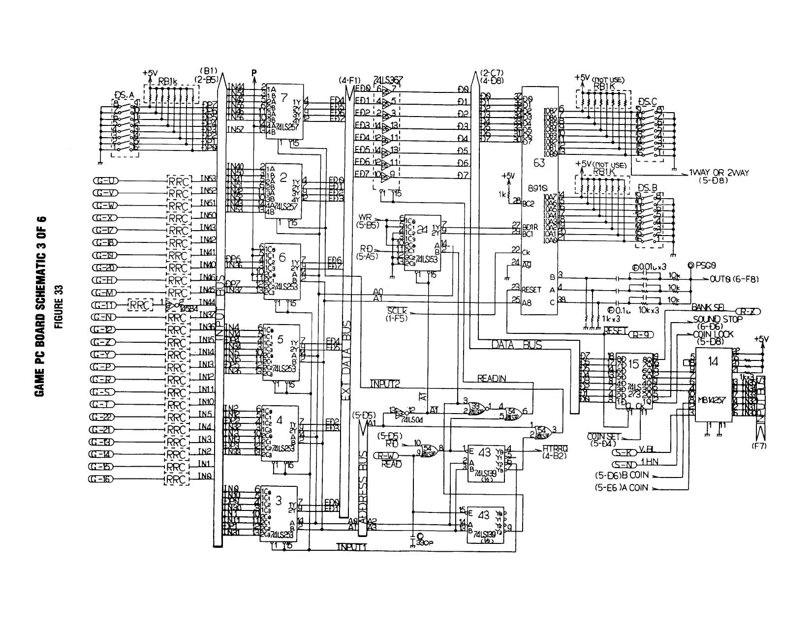
This page is a drawing, shown as the original scan.
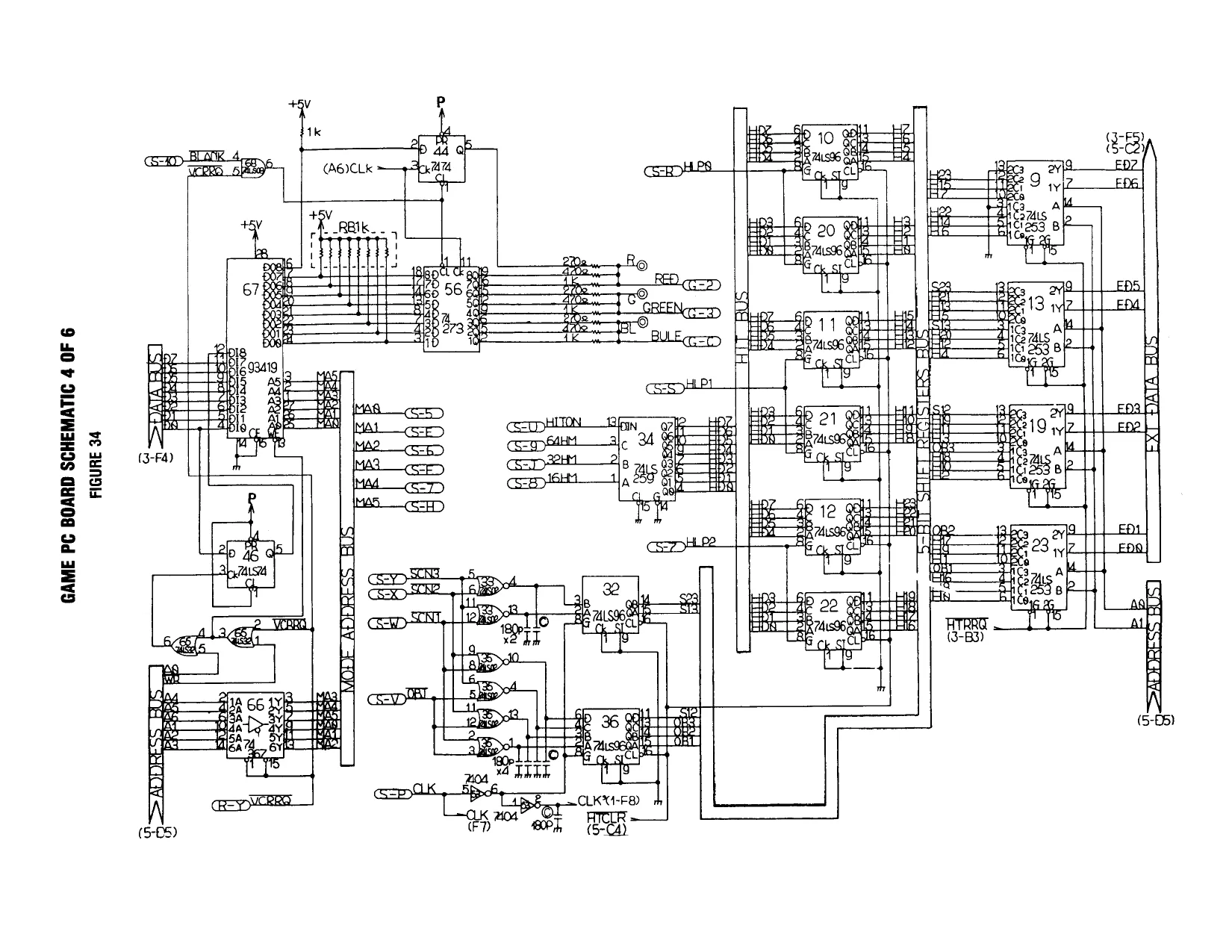
This page is a drawing, shown as the original scan.
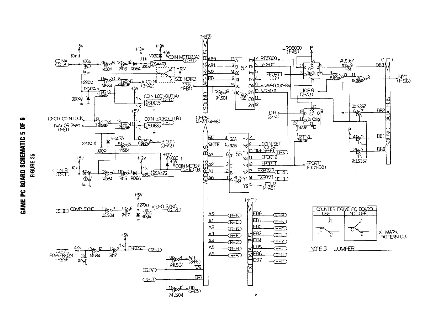
This page is a drawing, shown as the original scan.
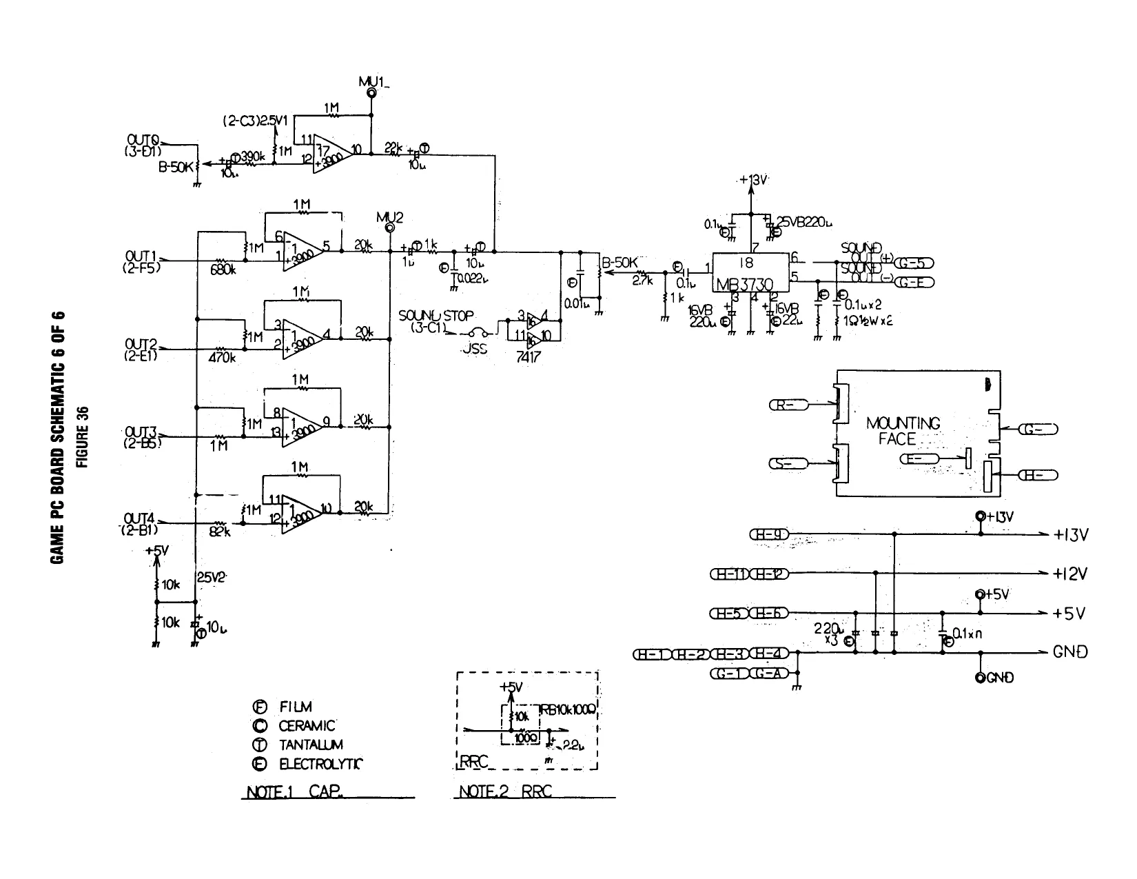
This page is a drawing, shown as the original scan.
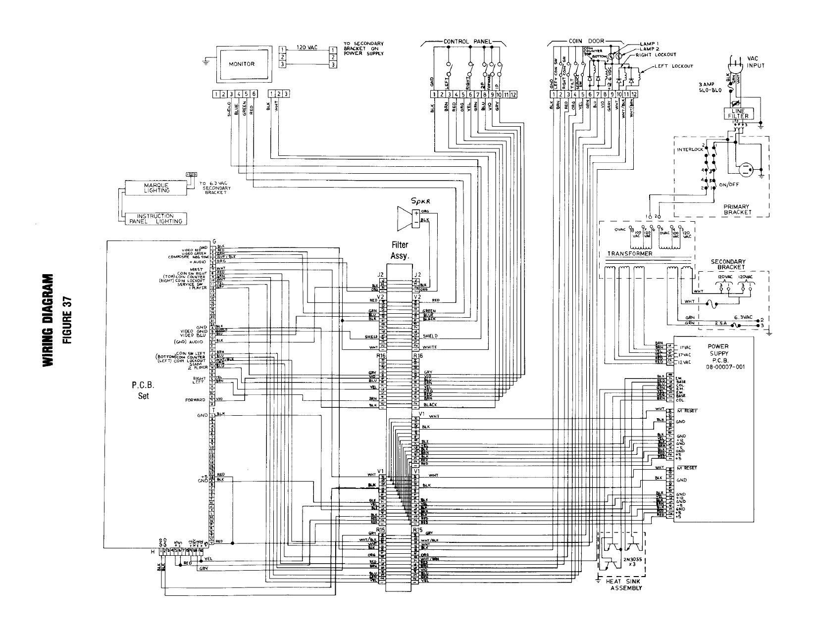
This page is a drawing, shown as the original scan.