Devil Zone
Devil Zone (Universal, 1980) · Manual · 35 pages · 28 sections · original scan
COSMIC SERIES——
DEVILIW
Operation, Maintenance
and
Service Manual
UNIVERSAL
CONTENTS
|, Features of this machine... ...... 6... cece cece eee ence ene eeeeee 1 11, How to handle and maintain this machine. .......... Pee pecan ea eee 2 I. How to play... . cece cece cere rere eee e rete teen eeeee 3 IV. Various optional settings... 0.2.2.2... 0 22 e ec eect eee eee n ene ene 4 A. Positions of dip switches.......... 0. cece cece eect eee eee 4 B. Setting the option (dip switches).......... 0... c cece eee eee eens 4 C. Volume controller knob 1.2... 2... cece eee eee eee 5 V. TV monitor... 0... eee cece e eee eee ee WS 6 he EUR a wee ee Bee 5 A. Adjustment of TV picture screen 2.1... cece cece tee eee 5 VI. Upright type parts catalog ...... A. Component parts related to cabinet (outside) ............---.00---5 6 B. Drawing of circuit board mounting positions .......... 00. c eee ee eee 7 C. FUSES oo eee eee eee eee eet e eens deve siecereusener ernest 7 D. Component parts related to cabinet (inside) ....... 00.000 eee ee eee eee 8
- Operating panel assembly ........ 0c c cece eee eee eee teens 8
- Door assembly and parts list... . 0... cece eects 9
- Lever assembly and parts list 2.0... . 0... cece cece rete ee teens E. Component parts related to switches in the cabinet ... VII. Table type parts catalog .......... 000 cece ee eee oe A. Component parts related to cabinet (outside) B. Component parts related to cabinet (inside) .
- Inside cabinet B) Fuses 2a cea nce cena ae coer erewmereeveenence cies
- Operating panel assembly . VIII. Circuit board A. Circuit board IC location and parts list
- Main circuit board IC location and parts list...
- Sub-circuit board (1) 8013-V1 IC location and parts list
- Sound circuit board IC location and parts list .......... 0.000008
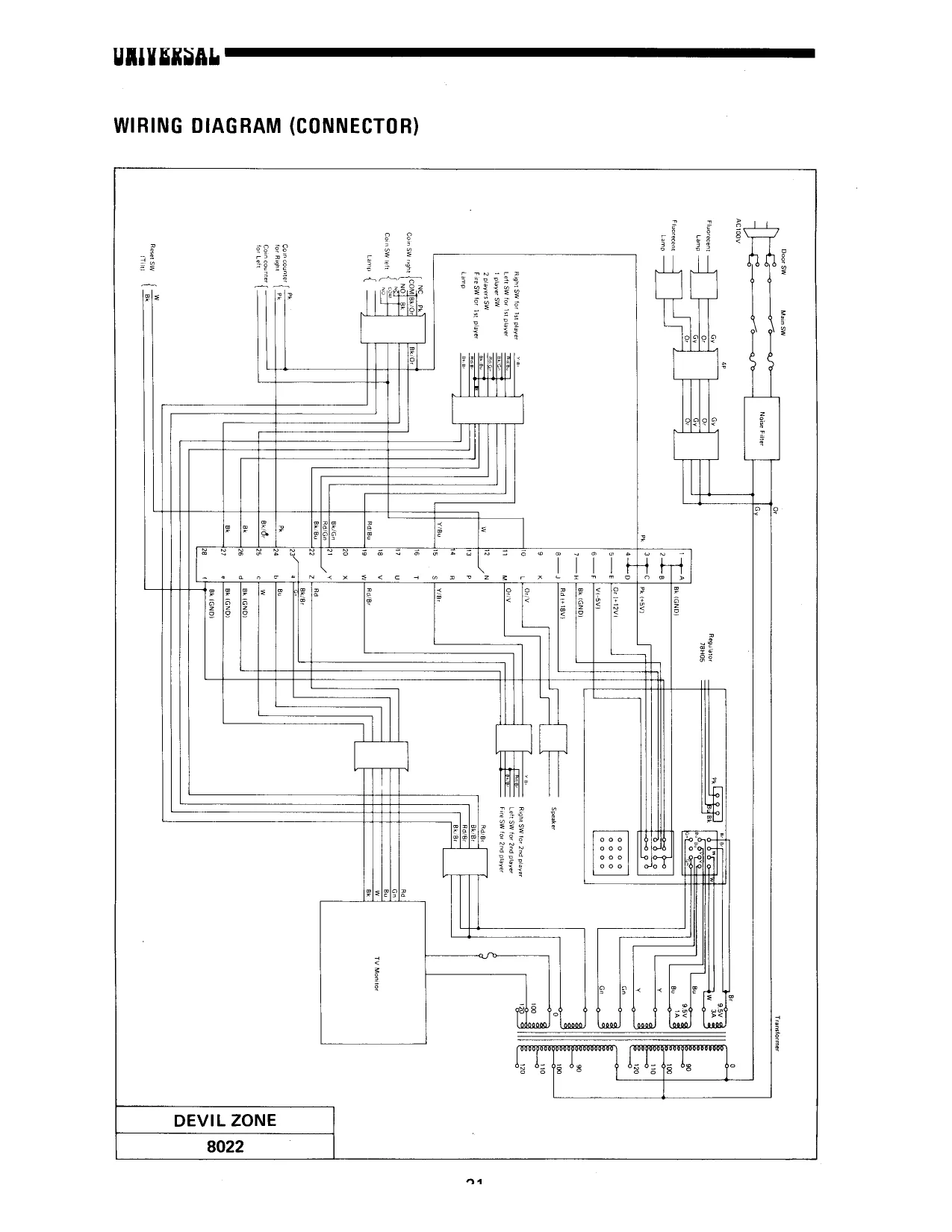
- Sub-circuit board (2) IC location and parts list . Sub-circuit board (2) block diagram Wiring diagram (connector) Sound block diagram .... Power source block diagram Block diagram . 6... ccc cee cece eee tree tee eet ene t eens Schematic diagram (20” color) . Schematic diagram (14 color) ....... 0.0.0 c cece eee eee eens Main block diagram ...... 060. cee cece cette eee eee teen nee Postface ...
Fig. 1 Fig. 2 Fig. 3 Fig. 4 Fig. 5 Fig. 6 Fig. 7 Fig. 8 Fig. 9 Fig. 10 Fig. 11 Fig. 12 Fig. 13 Fig. 14 Fig. 15 Fig. 16 Fig. 17 Fig. 18 Fig. 19 Fig. 20 Fig. 21
eee mrad
ee eee REFERENCE DRAWING
Positions of Dip Switches...........005ee eee ween e eee wee eeeee 4 Position of Volume Controller Knob ........-0 00 csc cece eeeeneneee 5 Component Parts Related to Cabinet (Outside) Circuit Board Mounting Positions . . Side View of Circuit Board Mounting Positions . . Fuses in the Power Source Unit... . Fuses in the Power Circuit Board... Component Parts Related to Cabinet (Inside). ............--00 eee e eee 8 Operating Panel Assembly ........ eee See ce reese 8 Inside View of Door Assembly ............2. 00005 beeen eee enee 9 Lever Assembly sea Component Parts Related to Switches in the Cabinet Component Parts Related to Cabinet (Outside) ...............-200005 Component Parts Related to Cabinet (Inside). ..............-200000 ee Fuses in the Power Source Unit ........ 6. ses e cece e eee eects 14 Fuses in the Power Circuit Board ........- 00sec seer cece eeeeceee 14 Operating Panel Assembly ......... 0.000 ee cece eee e eee eee 14 Main Circuit Board .. . . 15 Sub-circuit Board (1) 8013-V1 2.6... cece eee eee eee eee 16 Sound Circuit Board .. 6.0.0.0... cece cece eee eee eens 7 Sub-circuit Board (2). .... 0.0... cece cece eee eee e nee eenee 19
- WHEN ORDERING PARTS —
Since each component part is indicated by block, definitely specify both the corresponding Fig. No. and part No. within the Fig. when placing an order for it.
tnt tnt test
|. FEATURES OF THIS MACHINE
- The game packs in excellent features capturing the hearts of players.
- The lever control system is simple to handle.
- At the flick of a dip switch, you can select among extended play, the number of LASER SHIPs and time of appearance of an additional LASER SHIP, etc.
- High score for the day is always displayed on the screen.
- Finely disigned cabinet and fascinating acoustic effects.
- The 6 highest scorers can register their name on the screen.
NITERSAL
Il. HOW TO HANDLE AND MAINTAIN THIS MACHINE
Since the UNIVERSAL’s DEVIL ZONE employs a color TV receiving set, be careful not to shake it during transit and when carrying it about.
Install it at a location which is not exposed to direct sunlight. In order to prevent the inside temperature rising, avoid as much as possible a location near a heater, etc.
Since the grounding terminal is visible, be sure to connect it to a grounding conductor.
Insert the power cord into the outlet and turn on the switch.
Even if the solid-state module seems to be out of order, do not check the circuit by means of a circuit tester, etc., since the internal voltage of the tester, etc. may sometimes break down the IC.
Make sure the machine is well ventiated. If the temperature of the IC and transistor is lower than 60°C, the function normally and may be considered reliable. If it exceeds 60°C, their performance cannot be guaranteed.
Make sure that the connector, etc. is not disconnected.
Whenever connecting the power cord of the solid-state module to, or disconnecting it from, the outlet, be sure to turn the power off.
Although the products of UNIVERSAL are manufactured with the utmost care, they may develop malfunctions when used for long periods. So, be sure to chek this machine daily.
Il. HOW TO PLAY
- A fleet of space devils floating in the far away space. They will come flying in a four-plane formation to assault you. Destroy them by using your fire beam gun while dodging their missiles or dash.
- When the last plane of the four-plane formation began assaulting while turning, destroy it at as remote a position as possible, and you can score high points.
- Scoring 3,000 pts awards another spaceship.
- The 6 highest scorers can register their name on the screen after the end of the game. By working the lever move the carsor until it reaches under either of the alphabets, numerals and symbols aimed at, and drive it in place by using the fire button.
0 “
—s 200 £,—______——— 100
& 60
WV. VARIOUS OPTIONAL SETTINGS (1-way, 2-way common version)
A. POSITIONS OF DIP SWITCHES [ POAED Ah ARD (1
MAIN CIRCUIT BOARD 3013:V1
| Dip sw B ON Dip SW A
| ON | {In the case of 2-way, turn | GBBSEEE g | (Used in the |
| ‘ BEBEBSREY) | sws.4toorr: | 1234567 8| | caseof 2way | |
| OFF [1234567 8| | 'n the case of BP dip switch, | alone) |
SW7, 8 are not used.)
Fig.1 Positions of Dip Switches
B. SETTING THE OPTION (DIP SWITCHES) [Dip Switches A] [Dip Switches B]
- Change-over setting of the mode of game * Used in the case of 2-way chute alone. (SW1) At that time, be sure to turn SW3, 4 of
| Style | swi | Dip Switches A to OFF. |
| Table | OFF | ; |
- \. 4
Upright ON a. Right chute (SW1, 2, 3, 4)
Coin | Creat [ swi [| Sw2 [ sw3 | swa 1 1__| ofr | OFF | OFF [ OFF
| 2. Setting the number of LASER SHIPS | 1 | 2 | OFF | OFF | OFF | ON | ||||
| 1 | 3 | OFF | OFF | ON | OFF | |||||
| for game (SW2) | 1 | 4 | OFF | OFF | ON | ON | ||||
| Number of | sw2 | 1 | S | OFF | ON | OFF | OFF |
| ? | 2 | i | OFF | ON | OFF | ON |
LASER SHIPS 2 2 ON [OFF
| 2 Ships | ON | 2 | 3 | ON_| | ON |
| 3 Ships | OFF | 3 | 1 | OFF | OFF |
| 3 | 2 | OFF | [ON |
3 3 —[ON [OFF
| 3. Setting the game charge (Coin & Credit) | 3 | 4 | ON | ON | ||
| 4) | 4 | 1 | OFF | OFF | |||
| (sw3, | [4 | 2 | OFF | ON | |||
| Coin, Credit | [ Sw3 | sw4 | | 4 | 3 | ON | [OFF | |
| 1Coin 1Credit | ON | ‘ON | : | : | oi | ee | |
| 1 Coin 2Credits| | OFF | ON | b. Left chute (SW5, 6, 7, 8) | |||
| 2 Coins 1 Credit | ON | OFF | Coin [| Credit | Sw5 | Sw6é | sw7 | swe | |||
| Setby using | 1 | 1 | OFF _| OFF | OFF | OFF | |||
| i | 2 | Orr | OFF | OFF | ON | ||||
| Dip SW B for | OFF | OFF | 1 | 3 | orf | OFF | ON | OFF | |
| 2-way chute | 1 | 4 | OFF | OFF | ON | ON | |||
| 1 | 5 | OFF | ON | OFF | OFF | ||||
| 2 | 1 | OFF | ON | OFF | ON | ||||
| 4, Setting the required score for an | 2 | 2 | ore | ON | On | OFF | |
| an | 2 | 3 | FF [| on | On | ON | |||
| additional LASER SHIP (SW5, 6) | 3 | 7 | ON-OFF | OFF] | OFF | |
| Score for Extra | Sw5 | SW6 | 3 | 2 | ON, | OFF, | OFF J ON | |
| 2000 points | ON | OFF | 3 | 4 | ON | OFF | ON | ON | |
| 3000 points | OFF | ON | 4 | 1 | On | ON [ OFF | OFF | |
| A | 4 | 2 | on | ON | OFF [ ON | |||
| 5000 points | OFF | OFF | a | al | ON | TON” | ON 1 OFF |
| No extra | ON | ON | 4 | 4 | on [| on [ on [ ON |
UPRIGHT TYPE
This documentation provides standard information. Universal reserves the right to change without notice.
VI. UPRIGHT TYPE PARTS CATALOG
A. COMPONENT PARTS RELATED TO CABINET (OUTSIDE)
OUTSIDE CABINET PARTS LIST Fig.3 Component Parts Related to Cabinet (Outside)
Knob 32-Dim. Coin indication panel Ref. No. Name Ref. No. Name
| 1 | Title panel | 11 | Title panel fixture |
| 2 | (lustrated glass A | 12 | Caster |
| 3 | IMustrated glass B | 13 | Coin slot |
| 4 | CRT | 14 | Main door |
| 5 | Cash box door | 15 | Push button (1 player) |
| 6 | Sticker for game rules | 16 | Push button (2 players) |
| 7 | Push button (Fire) | 7 | Operating indication panel |
| 8 | Cabinet proper | 18 | Control lever (general name) |
5 . fal na
UNIVERSAL
B. DRAWING OF CIRCUIT BOARD MOUNTING POSITIONS
TV circuit board
Main circuit board
Sub-circuit board Sound circuit board Power source circuit board+ Power source unit +} AS Le es The sound volume can be controlled from this opening.
Before removing the TV monitor, remove the reinforcing lever at the back door.
Container Main circuit board
Fig.4 Circuit Board Mounting Positions
C. FUSES
Fuses in the power source unit Fig. 5 Side View of Circuit Board Mounting Positions
Fuses in the power circuit board
(oH)
Fuse
Fuse
Fuse
Fuse TV use table tap 100V
3A 6.3V for pilot lamp 5A for TV } 5A 100V, for the main use [Fuse }+-3A for +12V
Fuse 1 3A for +20V
Fuse 3A for -5V
Fuse [|—7 8A for +5V
Fig.6 Fuses in the Power Source Unit Fig. 7 Fuses in the Power Circuit Board
D. COMPONENT PARTS RELATED TO CABINET (INSIDE)
a — Operating panel assembly b — Door assembly c — Lever assembly
Fig.8 Component Parts Related to Cabinet (Inside)
- Operating panel assembly
Operating panel face fixture ass’y Switch ass’y for 2 players Lever ass’y
= —]
S fo} @ OF 6 | Wiesel, 5 ‘e a @ 7 ®) 2 | \ @ ® e |? | ii \ | Miniature lamp Switch ass'y for 1 player Fire button switch ass’y
Fig.9 Operating Panel Assembly
UNIVERSAL
- Door assembly and parts list
r
DOOR ASSEMBLY PARTS LIST Fig. 10 Inside View of Door Assembly
Ref. No. Name ___|_Ref. No. Name
| 1 | Main door | 13 | Coin slot shute holder |
| 2 | Returning soucer | 14 | Rejector |
| 3 | Lamp & plastic plate bracket | 15 | Sensor slot |
E 4 Rearing 16 Micro switch
| 5 | Coin slot shute | 17 | Key sets |
| 6 | Returning button | 18 | Miniature lamp |
| 7 | Coin slot | 19 | Miniature lamp socket |
| 8 | Slot plate | 20 | Coin indication panel |
| 9 | Transmission shaft | 21 | Hexagon socket head screw |
| 10 | Rotary bracket | 22 | Stam switch |
| 11 | Rejector bracket | 23 | Slam switch holder |
12 Rejector case
- Lever assembly and parts list
LEVER ASSEMBLY PARTS LIST Fig. 11 Lever Assembly
Name Ref. No. Name
| 1 | Knob 32-Dim. | 8 | Spring holder |
| 2 | Lever shaft | 9 | Blades switch |
| 3 | Lever guide & stopper | 10 | Blades switch |
| 4 | Transmission bar | ia | Spring holder with nut |
| 5 | Nut with stopper | 12 | Bolt |
| 6 | Switch bracket | 13 | Bolt |
7 Spring
E. COMPONENT PARTS RELATED TO SWITCHES IN THE CABINET
®
® ©
@ Ht fo) ope SS
The method of illumination; for the title panel and the illustrated glass may be subject to change for some reason or other.
Fig. 12 Component Parts Related to Switches in the Cabinet
INSIDE CABINET PARTS LIST
a4 Name Ref. No. | Name —_]
| 1 | Fluorscent lamp assembly | 8 | Micro switch |
| 2 | Fluorscent lamp assembly | 9 | Blades switch |
| 3 | Blades switch | 10 | Miniature lamp assembly |
| 4 | Blades switch | 11 | Door switch |
| 5 | Blades switch | 12 | Toggle switch |
| 6 | Blades switch | 13 | Micro switch |
| 7 | Miniature lamp assembly | 14 | Slam switch |
TABLE TYPE
This documentation provides standard information. Universal reserves the right to change without notice.
VII. TABLE TYPE PARTS CATALOG
A. COMPONENT PARTS RELATED TO CABINET (OUTSIDE)
1st player side
> < ® ® | ®O a6)
@)
2nd player side
- @
OUTSIDE CABINET PARTS LIST Fig. 13 Component Parts Related to Cabinet (Outside)
Name Name
| 1 | Operating indication illustrated panel | 13 | Glass fittings |
| 2 | Control lever | 14 | Cash box door key |
| 3 | FIRE button | 15 | Cash box door |
| 4 | Coin slot frame | 16 | Speaker (x2) |
| 5 | Selector plate (1) | 7 | Leg (left) |
| 6 | Selector plate (2) | 18 | Leg (right) |
| [not used in case of 1-way] | 19 | Foot | |
| 7 | Cancel button | 20 | Foot support |
| 8 | Push button ass’y (for 1 player) | 21 | Leg adjuster |
| 9 | Push button ass’y (for 2 players) | 22 | Thumbscrew (x8) |
| [_ 10 | Cancel coin receptacle | 23 | Power cord (AC) |
| 11 | Ventilating panel (x3) | 24 | Door key |
| 12 | Sticker for game rules (x2) | 25 | Cabinet corner box |
an
\
B. COMPONENT PARTS RELATED TO CABINET (INSIDE) :
- Inside cabinet n
@)
®
© ®
TV Monitor Control (1st player side)
Fig. 14 Component Parts Related to Cabinet (Inside)
INSIDE CABINET PARTS LIST
Ref. No. Name Ref. No. Name
| 1 | CRT (14” color) | 11 | Power source unit |
| 2 | TV monitor control | 12 | Demagnetization switch |
| 3 | Rejector ass’y | 13 | Door lock ass’y |
| 4 | Coin micro switch | 14 | Main circuit board |
| 5 | Coin counter | 15 | Sub-circuit board (1) 8013-V1 |
| 6 | Table lock mechanism ass’y | 16 | Sub-circuit board (2) |
| 7 | Butterfly plate ass’y | 7 | Sound circuit board |
| 8 | TV monitor circuit board | 18 | Cash box |
| 9 | Power source circuit board | 19 | Metal door fixture |
(10 Door switch _|
- Fuses
Fuses in the power source unit
Fuse 3A 100V, for TV
F 3A 100V Ose power source
Fig. 15 Fuses in the Power Source Unit
- Operating panel assembly Fuses in the power circuit board
Fuse 3A for +12V
Fuse 3A for +20V
Fuse 3A for -5V
Fuse 8A for +5V
Fig. 16 Fuses in the Power Circuit Board
Push button ass‘'y ass'y Control lever switch Control lever ass’y
Fig. 17 Operating Panel Assembly
Vii. CIRCUIT BOARD
A. CIRCUIT BOARD IC LOCATION AND PARTS LIST
- Main circuit board IC location and parts list
16? m7
ie iz wi a aor sot [a sor
N panes | we] (aa
p 27167 rz) fos i a w
Connecto (24 pin) 283, a 15) t
L FZ] % S169 5188 518) s168
Et ]
| x | Fd | fa | e} | |e) | | | & |
| or] | 3} | |s} | fal | ds | é | a |
By 2a is R|a
| 82 | s| | |8 | g | |||
| x | sig) | /8) | 8) | |g | 4h) | 2| |
N we | 8
| a | Ra E| | 5] | |e | 2 | |) | & |
O
5 lS
| co} | ja] | je} | ig} | ig} | iB | a1 V2 |
a. alu
| 7 | oe | — | J |
Fig. 18 Main Circuit Board
[1] Integrated Circuit
| Item No. | O'ty | Description | ||||
| [“item No. | Q'ty | Description | 2716 | 8 | Nch MOS 16K bits EPROM | |
| 7400N | 4 | Transistor Logic | Z80 | 1 | Nch MOS CPU | |
| 7402N | 2 | mt | | | NE556 | 1 | Transistor Logic |
| an | Z | 7 | [2] Other Semiconductor Devices | |||
| 7410N | 2 | " | Item No. | Q'ty | | Description | ||
| 7416N | 1 | ” | 10D1 | 4] | Diode | |
| 7417N | 1 | " | . | |||
| 7420N | 2 | 7 | [3] Capacitors | |||
| 7425N | 1 | " | Rating | Description | ||
| 7474N | 9 | " | 100PF/12V | 1 | Ceramic Capacitor | |
| 7485N | 2 | " | 150PF/12V | 1 | fd | |
| 7486N | 5 | " | O.1uF/12V | 55 | ” | |
| 74107N | 2 | i | 1 F/50V | 1 | Chemical Capacitor | |
| 74S138N | 2 | = | 10uF/16V | 2 | " | |
| 74153N | 1 | " | 100uF/25V | 4 | ||
| 74157N | 4 | " | ||||
| 74161N | 6 | ” | [4] Resistors | |||
| 74166N | 4 | Lid | Rating | O'ty | Description | | |
| 74174N | 4 | " | MS1028AM | 3 | 1KQ Resistor Array | |
| 74175N | 1 | " | 102 | 1/4W | 3 | Carbon Solid Resistor |
| 74S189N | 4 | 64 bits Bipolar RAM | 472 | a | 3 | ” |
| 74S201N | 4 | 256 bits Bipolar RAM | 2702" | 3 | “ | |
| 74LS245N | 1 | Transistor Logic | 3302” | 1 | % | |
| 74LS253N | 4 | ” | 5102” | 3 | " | |
| 74259N | 2 | 1KQ | " | 8 | - | |
| 74283N | 1 | “ | 47KQ | 1 | v | |
| 74S288N | 1 | 256 bits Bipolar ROM | 4A7TKQ | 2 | ad | |
| 74298N | 1 | Transistor Logic | . | |||
| 74LS373N| | 2 | z | : | 7] ES] Misc | ||
| 2116 | 8 | Nch MOS 16K bits Dynamic | Name | Q'ty | Description | |
| RAM | Dipsw | [1 | 8 Elements Switch Array | |||
| I 2708 | 1 | Nch MOS 8K bits EPROM | X'-tal | 1 | 10.816MHz |
- Sub-circuit board (1) 8013-V1 IC location and parts list (Used in the case of 2-way alone) [2] Other Semi Conducter Devices Item No. | Q'ty Description |]
| 10D1 | 2 | Diode | | |
[3] Capacitors
Rating Q'ty Description
O.1uF/12V | 4 Ceramic Capacitor
| 1uF/50V | 1 | Chemical Capacitor |
Connector 40 pi i pe [4] Registors
| Fig. 19 Sub-circuit Board (1) 8013-1 [Rating | [Oy | Description | |||
| MS1028AM} | 1 | 1kQ Registor Array | |||
| 4712. | 1 | Carbon Solid Registor | |||
| 1kQ. | 1 | v | |||
| [1] Integrated Circuit | 47kQ, | 1 | “ | ||
| Item No. | Q'ty | Description | . | |||
| 7474N | i | Transistor Logic | [5] Misc | ||
| 74251N | 1 | a | Name | O'ty | Description |
| NE555 | 1 | Timer | Dip SW | 1 | 8 elements Switch Array |
UAIWERSAL
- Sound circuit board IC location and parts list
vn a Poveal ae?
| Fs | Res | 4 | we | 49 | |||
| BSR | IF | gt | so | ar saal | 3 | ||
| 2 | Re | cascls | 8 | Was | Ret | RSS | 8 |
; :
KIS * la
rc16 oe 9 gs REE RS4 ~~ gece = 4h
i
&
UNIVERSAL —8022-S
. 20 Sound Circuit Board
—~17—
RIVERSAL
[Location] Rating Description [Location] Rating Description [Location] Ri Description Ri 1K (Carbon solid resistor] |__72 BiK [Carbon solid resistor| | 35 O.1uF Ceramic 2 ik i 73 100K " 36 4.7uF ‘Chemical 3 1M a 74 100K = 16V 4 1K e 5 100K i 37 0.0474 Mila 8 100K * 76 100K 2 38 2.2uF Chemical 6 1K a 77 220K a 39 O.1uF Ceramic 4 7 100K a 78 100K 2 40 THF Chemical EY 1K = 79 100K a 16V 9 1M - 80 100K 2 ai O.1nF Ceramic 10 51K 81 100K a 42 | 0.022uF Mila 1 51K 82 120K = 43 0.01uF i 12 100K 83 TOOK a 44 100uF Chemical 13 iM * 84 100K a 16V 14 1K = 85 100K 2 45 aur * 6 470K * 86 100K a 16V 16 100K Z 87 220K a 46 100uF ” 17 100K a 88 100K a 16V 18 120K = [89 BIK = a7 a7uF ¥ 1K = 90 100K = 16V 100K c 91 100K 48 0.0684F Mila
| 400K | 92 220K | 49 0.068uF “ |
TOOK * 93 10K 50 O.01WE = 100K B 94 22K z 51 2200pF “ ik : 95 472 = 52 0.015uF = TOOK = 96 152 “ 53 1000uF Chemical
| 10K | 97 1.52 " | 16V |
10K "98 10K a 54 0.047uF Ceramic [ 10K 2 99 22K = 100K z 100K " Gi 100uF Chemical [Loca- TOR - = 1ev lion | [tem No. Description 100K a 2 100uF = jai | 2scoas N-P-N Transistor
| 33. 100K | 25V | 2 = i |
34 100K 3 0.iuF Ceramic 35 10K z 4 0.4uF a loi_|_isises ‘Switching Diode 36 1K . 5 0.1uF Z 3 " : 37 75K a 6 O.1uF 38 TOOK 7 0.1uF 7 RY | MSi038AM |10KR
| 39 BIK | 8 O.1uF 7 | Resistor Array |
40 100K ™ 9 One 2 = 1 41 100K a 10 O.1uF 3 “ “ 42 220K = 1 O.1uF i 43 220K = 12 0.022uF Mila lvRi | RVI6YP TKAIB) 45 220K ” 13 O.1ME Ceramic Variable Resistor 46 100K 4 Tue Chemical
| a7 5IK | 16Vv | C1 | ULN2003AN” | Darlington |
48 24K a 15 0.1uF Ceramic Transistor Array 49 12K a 16 0.014F Mita 2 | CDA0TICN | Quad 2-Input 50 1K © 7 6800pF 2 NAND Gate 51 1K aw 18 0.22uF Tantalum 3_|CD4013CN | Dual 0 Flip Flop 52 51K % 19 0.022uF Mita 4 | ULN2003AN | Darlington 53 10K 2 20 Not Used Transistor Array 54 330K ° 24 0.1uF Ceramic 5_| CD4049cN | Hex Inverting Buffer 85 10K = 22 O.1uF 7 6 | CDa040CN | 14-Stage Binary 56 Ls “ 23 uF Chemical Counters
| 57 100K = | 16V | 7 | uwa2an ‘Quadruple Operational] |
58 100K = 24 10nF ™ Amplifiers
| 59 100K a | 16V | 8 | NESSEN Dual Timer |
60 100K = 25 ‘4700pF Mila 9 [| CD4016CN | Quad Bilateral Switch 61 100K = 26 O.1nF Ceramic 10 | LM324N ‘Quadruple Operational 62 1K 2 27 0.022uF Mila Amplifiers 63 5iK 28 10uF Chemical 77 cM324n a
| 64 100K | 16V | 12_| NESSEN Dual Timer |
65 100K ” 29 0.01uF Mila 13 | LM324N ‘Quadruple Operational 66 330K ? 30 22H Chemical Amplifiers
| 67 75K “ | 16V | 14 | LM324N a |
68 100K a 3 0.01nF Mila 15 | NES55N Timer 69 100K i 32 ‘470pF Ceramic 16 | LM324N ‘Quadruple Operational 70 100K " 33 3300pF Mila Amplifiers 7 1K = 34 WE ‘Chemical 17_[_aPC1181H | Power Amplifier 16V 18_[_wPC1i81H =
UNIVERSAL
- Sub-circuit board (2) IC location and parts list
[1] Integrated Circuit [2] Capacitors
Item No. O'ty Description Q'ty 7400N Transistor Logic Rating 0.1uF/12V Description Ceramic Capacitor 7404N 7486N 74153N 74161AN 74166N 191N [3] Resistors O'ty Description
$288N 256 bit Bipolar ROM LS393N
- o]) wl aly|oie|sj—
Transistor Logic 2716 Nch Mos 16K bit EP ROM Rating MS1028M 1KQ Rogstor Array |
SOCKET (40P!N)
| $288 | 86 | 04 | | |
—)
| LS166 | 00 | LS393 | |
| LS166 | 153 | bp | 191 |
| LS166 | LS161 | 2716 | |
| LS166 | LS161 | 191 |
DP 191 —_— } Fig. 21 Sub-circuit Board (2)
DEVIL ZONE 8022 —7n
- Hx
- 5M.
- INVO
- Vau
- HLOAD- (31)(3a)(33) GND (38)(39)40) +5y
(15166) SasSSSSS INVO(9)
S8g58883
(5393) RED(24) GREENCa8) OND
@r)Ha_—4
SUB-CIRCUIT BOARD (2) BLOCK DIAGRAM
This page is a drawing, shown as the original scan.
SOUND BLOCK DIAGRAM
DEVIL ZONE
8022
Firing sound @)}—p58-}_"
oun Ultramoth |
Coin pattern ree clean ® :
UFO @)}4—Y>e%, Cocoon sound @)+—t>e*
Hit the 1st time ()
Laser ship explosion
Hit the 2nd time (@)
‘Music
Sound enable ><" — Set %, Speaker
POWER SOURCE BLOCK DIAGRAM
ato)
m4 an ne oe shen if =@ O00 le le
! re ; ©) + — —+©
a ee anes ane rye (2)
Panes Pte OO
- — [ +O 1 t@ L@
BLOCK DIAGRAM
D--{__Door sw. Main SW,
Ce Transformer TW. Monitor Power Supply Video Signal
Start SW.
Main Board ontroi Lever
i— Speaker
Fire SW.
Coin Counter
‘Sub VIDEO YA.161398 PWK.068 SUB VIDEO L_— connector H
stouca22
‘07 1907
So,
moodle 5 8208 e302 Ssoen _* ake
bo
THOT 25CE28(0 o ascaK510)
Rove “vnaoate a pwrort a naa ia se Sg ms vorest eg ne [33k '@ iw Ts 1 OW Y mae $ iw fv poo ‘8 = Fo fag jane
ura
ww
aso12sciars
2102 ee
ue evar GRD TW HS,
DEVIL ZONE
8022
3CHEMATIC DIAGRAM (20” color)
Sub VIDEO YA-161398 Pwk-068
Pwr 068
1 Sawtooth generator, vertical amplifier suis ove 2 Over voltage protector 2 Horizon
4 Vert
sty 5 Horizontal oscillator 6 Horizontal AFC
- Noise canceiler 8 SYNC separator 9 AFC pulse modification 10 Push-pull OTL vertical amplifier 11 Fiy-back pumping wo
the croeTKLM,
as [arg @ {) ©) Sloe tesa
Vive aarp ca
em a 9 i
Gait aaa6s We co
eesfoav (roa
He 18 vacor ToEN Hsyuc 470 Jel
Heposinon’
-H—
DEVIL ZONE
8022
SCHEMATIC DIAGRAM (14” color)
Sot Tem Tames
ame
ain Pw Saw tooth generator, vertical amplitier Over voltage protector
neva Horizontal drive
Vertical oscillation new Susi 5 Horizontal oscillator 6 Horizontal AFC 38c15730
Noise cancetler
SYNC separator
AFC pulse modification Beane
Push-pull OTL vertical amplitier Fiy-back pumping up
608 0603
YoIz20
vat woe aed VEWNG —
ae rosw7o
aa
TOraTSPIN Ow so caoy—vRCI367C Tes 101 Rott ‘Yhoa79, Sertanr aso anos 201 i PTR? £2002, 22 £200? sezona 65-64
Ou Z
"| To FBT apn SOV nh” | ‘ aa otis 2" ts 18¥ vasor 15110 HsyNe 470 sol 52008, i cs07 Hao cate ah 0.022 22% Ss
ied Aagr s
av ye
oe 2z08
3NOZ 1AaG
DEVIL ZONE
8022 MAIN BLOCK DIAGRAM No. 1
ec we 7 a24 a ee ay] COOOOOO ieee
eer | mas tee H x 5 i
g 3 wae 28 ; on g fi 33 BES 3 c
DEVIL ZONE
8022
DEVIL ZONE No.4
Oo.
8022 awe lent leave
oven He crue
Used in the case of 2-way alone
cock MAINBOARD CONNECTOR a4 ep
Encircled figures represent
the 16 pin IC socket’s pin number
pin number.
(apply to this drawing alone)
Sub-circuit board (1)
8013-V1 an 23,24 -——1 124 “We oD a as OO ve '——1)
1001 cuvoa aunos o1
COIN Ler