Hard Drivin' TM-327 3rd Printing
Hard Drivin' (cockpit, rev 7) (Atari Games, 1988) · Technical Manual · 114 pages · 152 sections · original scan
TM-327 ‘ait 3rd printing
This page carries no recoverable text. It is a drawing or a photograph. See the original scan.
A.
ATARI
GAMES
Hard Drivin’
OPERATOR’S MANUAL
Illustrated Parts Lists with
Copyright © 1989 by Atari Games Corporation. All rights reserved. No part of this publication may be reproduced by any mechanical, photographic or electronic process, or in the form of a phonographic recording, nor may it be stored in a retrieval system, transmitted, or otherwise copied for public or private use, without permission from the publisher. ‘The game play, all graphic designs, this technical manwal, its accompanying schematic diagrams, and the display manual are protected by the U.S. Copyright Act of 1976. This Act provides for substantial penalties for violating federal copyright laws. Courts can impound infringing articles while legal action is pending. If infringers are convicted, courts can order destruction of the infring-
In addition, the Act provides for payment of statutory damages of up to $50,000 per infringing transaction in certain cases. Infringers may also have to pay costs and attorneys’ fees and face an imprisonment of up to five years as well as fines of up to $250,000 in the case of individuals and up to $500,000 in the case of corporations. Atari Games Corporation will aggressively enforce its copyrights against infringers. We will use all legal means to immediately halt any manufacture, distribution, or operation of a copy of video games made by us. Anyone who purchases such copies risks forfeiting such a game.
Published by: Atari Games Corporation 675 Sycamore Drive P.O. Box 361110 Milpitas, California 95035
Printed in the U.S.A 3T
Produced by the Atari Games Technical Publications Department. ‘Technical Writing: Rosalind Hutton. Editing and Design: Andrea Dencker Illustration: Mary Ohanessian Sumner
Notice Regarding Non-Atari® Parts
You may void the game warranty (printed on the inside back cover of this manual) if you do any of the following: © Substitute non-Atari parts in the game.
- Modify or alter any circuits in the game by using kits or parts not supplied by Atari Games Corporaton.
- The power cord is properly plugged into a grounded three-wire outlet. © On games provided with an Electromagnetic Interference (EMD ground cage, be sure that the game printed-circuit boards (PCBs) are properly installed on the EMI ground cage and that the end board is securely installed with all screws in place and tightened, If you are still unable to solve the interference problem, please contact Customer Service at Atari Games Corporation. See the inside front cover of this manual for service in your area.
Hard Drivin’
1 Set Up How to Use This Manual 11 Operating the Simulator 1-2 Inspecting the Simulator. 1-2 Installing the Attraction Sign Assembly 1-2 Adjusting the Glides .... 1-3 Control and Switch Locations 1-3 Setting the Coin and Game Options. 1-4 Simulator Systems... 1-4 Maximizing Earnings 14 Simulator Driving... 2 Self-Test and Diagoostics: Program ROM and RAM Test Microprocessor and Board Test
Game Options.. Custom Game
Disable Broken Controls Screen Special Functions Screen. Main Board GSP Tests
Steering Wheel Subment Shifter Test Screen ......
Main Board ZRAM Test .. ADSP Board Tests Sound Board...
Installing the Dashboard Steering Assembly .. Greasing the Steering Assembh; Replacing the Steering Assembly Replacing the Steering Wheel Motor . Replacing the Steering Wheel Stop ... Table of Contents
Key Switch Assembly ........ Oiling the Key Switch Assemb! Replacing the Spring in the Key Switch Assembly... 3-11 Tightening the Screw in the Key Switch Assembly Actuator... Replacing the Switch on the Key Switch ‘Assembly... 312 Chutch Pedal .. Maintaining the “Clutch and Brake Pedals Replacing the Clutch Potentiometer Replacing the Clutch Springs ........
Repairing the Brake Testing the Switch, Switch Acuator Distance, and Pedal Movement... vo Testing the Stain Gauge and the Strain Gauge Bonding Replacing the Brake Switch Replacing the Brake Strain
Gas Pedal Assembly Lubricating the Gas Pedal . i the Gas Pedal ley Replacing the Gas Pedal Cable Spring Replacing the Gas Pedal Potentiometer .. Replacing a Broken Compression or Extension Spring on the Gas Pedal...
Installing a New Shifter Boot Removing the Reverse Latch Pin . Replacing a Shifter Potentiometer. Replacing the Shifter Magnet or Plate .. Seat Assembly Replacing the Seat Rod End Bearings Replacing Bearings on the Seat Pivo' Replacing Main Seat Bearings...... Replacing the Gears on the Seat Assembly Replacing the Small Gear 3-34 Replacing the Large Ge: 3-34 Replacing the Magnet on the Seat Assembly .. 3-34 Replacing the Seat Potentiometer 3-35 Video 3-36 Replacing the Video Display. Motor Amplifier Assembly Removing the Motor Amplifier Assembly.
Replacing Static-Sensitive Devices Cleaning the Coin Mechanism.
4 Ulustrated Parts Lists See the List of Illustrations that follows.
Statistics Sheet
Figure 1-1
Figure 2-1 Figure 2-2 Figure 2-3 Figure 2-3 Figure 2-5 Figure 2-6 Figure 2-7 Figure 2-8 Figure 2-9 Figure 2-10 Figure 2-11 Figure 2-12 Figure 2-13 Figure 2-14 Figure 2-15 Figure 2-16 Figure 2-17 Figure 2-18 Figure 2-19 Figure 2-20 Figure 2-21
Figure 2-22 Figure 2-23 Figure 2-24 Figure 2-25 Figure 2-26 Figure 2-27 Figure 2-28
Figure 2-29
Figure 3-1 Hard Drivin’
List of Illustrations
Attraction Sign Installation .......
Program ROM and RAM Test.. Microprocessor and Board Tests Instructions for Test Menu Screen... Test Menu Screen .. Coin Options Screen .. Game Options Screen Custom Game Options Screen. Statistics Screen... 2-9 Histogram Screen. Games Played by Day and Hour Screen 2-10 First Set Controls Screen. 2-11 2-11 2-12 2-13 2-13 Control Inputs Screen. Set Clock Screen... Disable Broken Controls Screen. Special Functions Screen. GSP Tests Screen MSP Tests Screen. Main Board Controls Screen Pots: 8-Bit Screen. Pots: 12-Bit Screen Steering Wheel Submenu Screen...
Send Force Screen . 2-17 Shifter Screen... ~ 2-17 ROM Checksums Screen 2-17 ADSP Board Tests Screen... . 2-18 ADSP ROM Checksums Tests Screen 2-18 Sound Board Tests Screen. A Sound Board Sound Wave ROM. Checksums Screen DIP Switch and LED Locations on the Main PCB..... we 2-19
Removing and Installing the Dashboard..... Figure 3-2
Figure 3-3
Figure 3-4
Figure 3-5 Figure 3-6
Figure 3-7
Figure 3-8
Figure 3-9
Figure 3-10
Figure 3-11 Figure 3-12
Figure 3-13 Figure 3-14
Figure 3-15
Figure 3-16 Figure 3-17
Figure 4-1 Figure 4-2 Figure 4-3 Figure 4-4 Figure 4-5 Figure 4-6 Figure 47 Figure 4-8 Figure 4-9
Figure 4-10 Figure 4-11 Figure 4-12 Figure 4-13 Figure 4-14 Steering Wheel Has No Feedback and You Have Tried the Set Controls Screens .. Steering Wheel is Turned ll the Way to One Side and You Have Tried the Set Controls Screens. Steering Wheel is Jerky an Tried the Set Controls Screens . Maintaining the Steering Wheel Maintaining the Key Switch Assembly Clutch, Seat, or Gas Pedal is Not Working or Working Erratically and You Have Tried the Set Controls 3-6
Brake is Not ‘Working or Working Erratically and You Have Tried the Set Controls Screens .... Rewinding the Gas Pedal Pulley Cable .... Maintaining the Gas Pedal Shifter is Not Working or Working Exratically and You Have Already Tried the Set Controls Screens. Maintaining the Shifter ...... Seat is Not Locked When it Should Be and You Have Already Tried the Set Controls Screens ... Seat is Locked When it Should Not Be and You Have Already Tried the Set Controls Screens Maintaining the Seat Assembly Removing the Video Display ...
Cabinet-Mounted Assemblies...
Clutch and Brake Pedal Asse ly. Gas Pedal Assembly Coin Acceptors, Inc, Coin Door Assembly Power Supply ly. Hard Drivin’ Main PCB Assembly APU PCB Assembly .... Shifter PCB Assembly
Hard Drivin’
Table 1-1
Table 2-1
Table 2-2 Table 2-3 Table 2-4
Table 2-5 Table 2-6
Table 2-7 Table 2-8
Table 2-9 Table 2-10
Table 3-1 Table 3-2 Table 3-3
Table 3-4 List of Tables
Simulator Specifications.
Using the Self-Test Screens and
Custom Game Option Settings ‘When to Use the Special Function Items... Program
Voltage Inputs and Test Points on the Simulator PCBs... jee the ie Seeing Assembly ... aoe Table 3-5 Table 3-6 Table 3-7 Table 3-8
Table 3-9
Table 3-10 Table 3-11 Table 3-12 Troubleshooting the Key Switch... Troubleshooting the Clutch Pedal Troubleshooting the Brake Pedal ...... Troubise oda t the Gas Pedal
Assembly Troubleshooting the Seat ‘Assembly. . 3-28 ‘Troubleshooting the Video Display... 3-36 Troubleshooting the Speakers. - 3-38
Safety Summary
The following safety precautions apply to all game operators and service personnel. Specific warnings and cautions will be found in this manual whenever they apply.
Set-Up
How to Use This Manual
This manual is written for operators and service personnel. It provides information for setting up, driving, testing, and maintaining your Hard Drivin’™ simulator. The manual is divided into the following chapters:
- Chapter 1 contains set-up and simulator driving information.
- Chapter 2 contains self-test procedures and additional diagnostic tests. The self-test is important in the Hard Drivin’ simulator. You can troubleshoot the PC boards, main circuits, and controls using the more than 60 screens in the self-test. You should regularly test the boards and controls with the selftest to keep your simnulator in peak condition and at top earnings.
- Chapter 3 contains the preventive maintenance schedule for the simulator and the repair procedures, flowcharts, and troubleshooting tables for each control. If you have problems with your simu- Jator, use this chapter to troubleshoot and to repair it. Be sure to perform the preventive maintenance tasks to keep your simulator in good condition. Chapter 4 contains the illustrated parts lists.
Set-Up
Operating the Simulator
To operate your simulator for maximum income, make sure your players know that the simulator is designed to be driven like a real car. You should regularly do the automated self-test and check the controls with the Control Inputs screen in the self-test. By using the selftest regularly, you can find and fix problems immediately. This lets you keep your simulator in top condition.
Inspecting the Simulator
This cabinet should be connected to a grounded threewire outlet only. If you have only two-wire outlets, we recommend that you hire a licensed electrician to install grounded outlets. Players can receive an electrical shock if the cabinet is not properly grounded. Inspect your Hard Drivin’ simulator carefully to ensure that the simulator is complete and was delivered to you in good condition. Inspect the cabinet and seat as follows:
- Examine the exterior of the cabinet for dents, chips, or broken parts.
- Open the lower service door and the small top service panel. (Leave this top panel open so you can install the attraction sign.) Unlock and open the coin doors. Inspect the interior of the cabinet as follows: a. Check that all plug-in connectors on the cabinet harnesses are firmly plugged in. Do not force connectors together. The connectors are keyed so they fit only in the proper orientation. A reversed connector can damage a printed-circuit board (PCB). This will void your warranty. Hard Drivin’
Table 1-1 Simulator Specifications
. Characteristic Specification Power Consumption 635 W maximum Line Fuse Rating 7 Amps Line Voltage 102 to 132 VAC Temperature 5° to 38°C @7° to 100° F) Humidity Not to exceed 95% relative ‘Width 31 1/2 in. @1 cm.) Depth (seat pushed in) 62 1/2 in. (160 cm.) Height 77 in. (197 cm.) Weight 750 Ibs. (341 kg.)
b. Ensure that all plug-in integrated circuits on each PCB are firmly plugged into their sockets. c. Inspect the power cord for any cuts or dents in the insulation. d. Inspect the power supply. Make sure that the correct fuses are installed. Check that the harness is plugged in correctly and that the fuse block cover is mounted in place. Check that the green ground wires are connected. e. Inspect other sub-assemblies, such as the video display, controls, printed-circuit boards (PCBs), and speakers. Make sure that they are mounted securely and that the ground wires are connected.
Installing the Attraction Sign Assembly
The attraction sign assembly is shipped uninstalled with the simulator. Mount the sign on the back of the cabinet as shown in Figure 1-1. The hardware for assembling the sign and for mounting it is shipped in the cash box. This hardware consists of ten 1/4-20 button-head screws 2 inches long with black washers.
- Lay the attraction sign face down on a clean surface where it will not be scratched.
- Lay the H-shaped attraction frame on top of the sign. Put the short ends of the H on top of the sign. The harness connection in the leg should face the sign. Attach the harness from the sign to the hamess in the leg. Push the extra wires inside the leg of the attraction frame.
- Install six screws and washers through the attraction frame and into the attraction sign. Tighten the screws.
Hard Drivin’ Set-Up
Afrsecion Frame
Figure 1-1 Attraction Sign Installation
Now install the attraction sign assembly on the back of the simulator. You need the other four screws and flat washers.
- Open the small top rear panel of the simulator if you have not done so already.
- Connect the simulator hamess to the harness in the left leg of the sign. Now push the extra wires back inside the simulator. Be careful that the harness does not lie on the motor amplifier assembly, mounted on the side of the cabinet. . Put the attraction sign against the cabinet, and line up the four holes in the legs with the four holes in the cabinet. . Put the button-head screws and black washers into the legs, and screw them into the threaded holes.
Adjusting the Glides
After you move the simulator into location, screw out the adjustable glides in the base to support it. The Hard Drivin’ simulator is heavy, and if you do not put down the glides, the casters may be damaged. Before you move the simulator, retract the glides so they are not damaged.
Control and Switch
Locations
Power On/Off Switch The power on/off switch is located at the bottom rear of the cabinet. Volume Control The volume control is located behind the upper coin door. Self-Test Switch The self-test switch is located behind the upper coin door. See Chapter 2 for a complete description of the self-test.
Auxiliary Coin Switches An auxiliary coin switch is located on the component bracket behind the upper coin door. Use the auxiliary coin switch to give players coin credits.
Set-Up
Coin Counter The coin counter is located behind the upper coin door. The coin counter records the number of coins deposited. It does not count the credits given by the auxiliary coin switch.
Setting the Coin and Game Options
The Hard Drivin’ coin and game options are set in the self-test. Refer to Chapter 2 for the recommended settings and the procedure for setting the options.
Simulator Systems
The Hard Drivin’ simulator uses seven PCBs to give a realistic look and feel to the driving. These PCBs are the main PCB, the ADSP PCB, the motor amplifier PCB (with two motor amplifier driver PCBs), the shifter
tn PCB, the brake PCB, the audio and power Pili iss (mounted on the power supply assembly), and the sound PCB. These PCBs control simulator software, the video display, and the controls. The main PCB, which is the largest, holds the 68010, the GSP, and the MSP microprocessor systems. The 68010 system contains program RAM and ROM. The GSP (Graphic Systems Processor) microprocessor system controls the video RAMs (VRAMs). The MSP (Model Systems Processor) microprocessor system performs all the math functions. The ADSP board and the sound board are mounted with the main PCB. The motor amplifier PCB is mounted in a heatsink assembly located on the driver's left. It controls the steering wheel motor. The shifter PCB is located on the driver's right and controls the gear shifter effects. The brake PCB is located on the brake and clutch pedal assembly and controls the braking effects.
Maximizing Earnings
For maximum earnings, regularly maintain your Hard Drivin’ simulator following the instructions in Table 3-1, in Chapter 3. When you set up the simulator and when you collect wa awd
money, perform the automated self-test and check the controls with the Control Inputs screen in the self-test.
Simulator Driving This section describes the features and driving of the Hard Drivin’ simulator.
Introduction Slide into the contoured seat and adjust it to fit the length of your arms and legs. Put your feet on gas and clutch pedals and try the stick shift. Select manual or automatic transmission, turn the ignition key and you're off! It’s the ride of your life. You feel the tires grip the road when you take a wide turn at high speed. You're alerted to the smaliest change in the road by the feedback steering. You catch air as you fly the draw bridge and land on the down ramp. You control the car as it hoids the road on the dizzying vertical loop.
Driving Mode Hard Drivin’ might look like an arcade game but it drives like a real car. For the best lap times, drive Hard Drivin’ as if it were a real car. The main difference between Hard Drivin’ and a real car is that Hard Drivin’ is much safer to drive. A player can test the limits of our car and his skill with no risk of personal injury, and follow a course that does not exist anywhere in the real world. After inserting the proper number of coins to start the simulator, the player can select either an automatic or manual transmission. Turning the ignition key starts the simulator. Drivers can choose between the stunt track or the speed track by following the posted signs on the road. Each player has a certain (operator-selectable) amount of time to reach a checkpoint or the finish line. Crossing checkpoints and the finish line rewards the player with (operator-selectable) bonus driving time. With Hard Drivin’ a player can test drive a high-powered sports car on a real stunt course. He can jump a draw bridge, negotiate a high-speed banked turn and drive a 360-degree vertical loop. These thrilling stunts, among others, provide the ultimate realistic driving experience. Or maybe high-speed driving is a particular player's type of excitement. He can “put the pedal to the metal’ and try to keep control around the corners, weaving in and out of traffic while avoiding oncoming cars. All this, and more, await the player behind the wheel of Hard Drivin’. Players especially enjoy the unique instant replay feature on Hard Drivin’. Every time a player crashes, the
Hard Drivin’
simulator records and replays the crash sequence. Not only will the player find this entertaining, but it is also informative. The instant replay shows the player exactly what he did wrong and why he crashed. (if a player ‘wants to skip the instant replay, he can press the abort switch or turn the key when the replay starts.) A skilled player finds the ultimate competition in the “challenge” lap (or “grudge match” as we at Atari Games like to call it). The simulator remembers the path of the car driven by the best driver on record. When a player beats the qualifying lap time, he chal- Set-Up
lenges the car of the past winner in a head-to-head race, Hard Drivin’ is equipped with center-feel steering with continuous force feedback, adjustable swivel seat, gas, brake and clutch pedals, four-speed stick shift, and a medium-resolution monitor. You can add two after-market options to your simulator, a dollar bill acceptor and an overhead video display assembly. Atari Games is also making a limited edition of right-hand-drive Hard Drivin’ available. Contact your local Atari Games distributor for further information.
1-5
The Hard Drivin’ simulator is a complex machine. To keep it at peak efficiency and maximum eamings, you should regularly check the controls, RAMs, ROMs, PCBs, and microprocessor systems. You can check all of these when you switch on the self-test, Also in the self-test you can check the video display, the statistics, and set the internal clock. . If you cannot use the self-test because the screen is ‘dati, you can use a DIP switch on the main PCB to ind ‘ie source of the problem. If you are having elecyou can check the state of various
arly check the. following screens and
recommend you chétk.these when you
rtm RAMs and ROMs,’ the video RAMs, the MSP microprocessor system. wc] the sound PCB. The test takes about 5 eres run.
Test Menu screen. This 3 ows the tothe main PCB’ from the aon e pedal; gas pedal,’ clutch |, séat, \ SY wer With this information youre: easily % -how ‘the controls are working, ” 2 4 :
ings may drop, since the realistic ariving
feel is lost.
* Check the Statistics, Histogram, and Giémes ong
by Day and Hour screens: which show the statist _cal information about how and when your, simula. < weoag HE is. played: wae Table..2-1- shows‘ you, WHat tests and screens to use at a different times and for different problems. m ®
Self-Test
Automated Self-Test
When you enter the self-test, the simulator automatically tests the program ROM and RAM, the video RAM, If you do not want to wait for the systems and PCBs to be tested, then skip these tests by turning the key switch while in the program ROM and RAM screen, Figure 2-1. If you want to go to the attract mode, just turn off the self-test switch. the color RAM, the MSP microprocessor system, the DSP PC board, and the sound PC board. This test takes about five minutes (unless you bypass the test as described in the next paragraph). Program ROM and
RAM Test
When you enter self-test, the simulator tests the pro- ROM and RAM. The screen in Figure 2-1 shows the results of a program ROM and RAM test. The top of the screen shows the ROM test result, The numbers on the left and the letters on the top of the screen show the locations of the ROMs on the main PCB. If a white box appears, then the ROM there is good. If an empty box appears (as shown at 200U and
‘Table 2-1 Using the Self-Test Screens and Diagnostics
Explanation ‘When you switch on the self-test, the ‘automated self-test is performed, This tests the program RAM and ROM and the PCBs. You can skip the self-test by turning and holding the key as soon as you enter the self-test. If you cannot run the self-test at all, use the DIP switches to diagnose the problem. These are explained at the end of this chapter.
Problem or Type ‘Automated Self-Test
Test Menu Appears after the automated self-test. Select tests and information on this screen.
Regular Maintenance Regularly do the following:
- Do the automated self-test.
- Check the Operator Screens.
- Go to the Control Inputs screen to test the controls. Game Set-Up When you first set up your game, do the following:
- Do the automated self-test.
- Make sure the options on the Operator Screens are set correctly for your location, or set to the |
defaults.
- Go to the Control Inputs screen to test the controls. Set the clock, if necessary, using the Set Time screen.
Control Problem. 1. Do the Set Controls screens. Tf that does not correct the problem, go to the Control Inpuis screen and see if the input from | the control changes as you use the control.
- Go to Chapter 3 and check the troubleshooting table and maintenance information for that
control.
- ithe shifter, brake, clutch, oF seat potentiometer is broken and you cannot fix it immediately, ‘but still want to operate the game, turn off the control circuit in the Disable Broken Controls
screen, ny
Video Display Problem . Try the Monitor Test Patterns screens. . If you cannot go into the self-test or the screen is dark, use the DIP switch diagnostics.
. Do the automated self-test. . Choose the Special Functions screen that applies to your problems: the GSP, MSP, program ROM, ADSP PC board, or sound PC board test. Use the Set Time screen to set the internal game clock. This time is used in the statistics screen that shows games played by day and time and in the schedule for clearing the high score table. Electronics Problems pene
Game Clock
Use the DIP switches and the LEDs to diagnose the problem. These are explained at the end of
the chapter. Cannot Enter the Self-Test
2-2
corivin’
210U), then the ROM there is bad. If nothing appears, then nothing was tested there. ‘The RAMs are tested after the ROMs. If the RAMs have no errors, then you see the message Program RAM OK. If the test finds an error, then you see Bad Pro gram RAM At with the bad RAM location listed. This screen disappears after a few seconds and the self-test continues. However, the screen with the results of the complete self-test, shown in Figure 2-2, will show the message Bad Program ROM (or Bad
- Program RAM) if it found an error in the program ROMs or RAMs. .
Bay een
ae ae ey A ea ease
Gace bier ab ee eae ae es
" Figure 2-1 Program ROM and RAM Microprocessor and
Test Screen
ee After checking the program RAM and ROM, the automated self-test checks the simulator’s microprocessor and PC boards. It tests the video RAM and color RAM in the GSP microprocessor system, the DRAM in the MSP microprocessor system, the ADSP board, and the ae sound board. The test takes four to five minutes. You see the screen in Figure 2-2 when the test finishes. . If the system or board is good, OK follows the test name. If it is bad, the word Bad precedes the name of the board or system (except for the ADSP board test, which gives more information). If you have a bad system or board, then choose Special Functions from the test menu, choose the appropriate system or board tests from the special functions menu, and read the description of the tests in this chapter. A brief description of each microprocessor and board test performed in the self-test is below. PROGRAM ROM: Described above. PROGRAM RAM: Described above. = Feet
GSP VRAM: Uses the Simple GSP VRAM Test. (Described in the section Main Board GSP Tests.) GSP COLOR RAM: Uses the GSP Color RAM Test. (Described in the section Main Board GSP Tests.) MSP DRAM: Uses the MSP Verify Test. (Described in the section Main Board MSP Tests.) ADSP Board: Tests the ADSP board memory and the ADSP-2100. Most of the error messages are self-explanatory. (Does Not Respond generally indicates a missing board.) Sound Board: Tests the program ROM and RAM on the sound PC board. If any are bad, the message Bad Sound Board appears on the screen. Sound Wave ROMS: Tests the ROMs that have the sound waveform data. If any are bad, the message Bad Sound Wave ROMs appears on the screen.
BAO PROor AM HOM
ON
O S806 eG
Figure 2-2 Microprocessor and Board Tests Screen
Test Menu Screens
After the microprocessor and board test is finished, or you bypass it, turn the key to see the test menu screens. Turn the key once to see the screen with the instructions for moving and choosing in the test menu, shown in Figure 2-3. Turn the key again to see the test menu, To move down the menu, press the left coin switch. To move up the menu, press the right coin switch. You can choose the test menu item with the white letters by turning the key. The test menu, shown in Figure 2-4, is the most important screen in the self-test. Use this screen to choose the other screens and tests in the self-test. If you choose any item on this test menu, a new screen on that subject appears. Table 2-4 shows all the screens that appear in the self-test.
2-3
Self-Test
Figure 2-3 Instructions for Test Menu Screen
me i
a Figure 2-4 Test Menu Screen
Operator Screens
Choose the operator screens in the test menu by turning the key while the words Operator Screens are in white, (For information about moving in and choosing from the menu, see the section above.) If you are in the operator screens and want to go to the attract mode, first turn the key to go through the remaining operator screens. When you return to the test menu, turn off the self-test switch. These are the screens in the operator screens sub-
menu:
Coin Options
Game Options Game Statistics : Histogram of Game Times Error Count Games Played by Day and Hour ‘Hard Drivin’
The coin options are the first operator screen (see Figure’ 2-5). To move and choose in this screen, do the following:
- To move up or down the list, press the right or coin switch. ae © To change a setting, press the abort button and 2% ther coin switch.
- To return to the setting originally on the screen, press the abort button and turn the key.
- To exit the screen, tum the key. You can change an option when it is enclosed in the blue box. The default setting of each option is green. The other settings are blue when you select that option. (The other settings are white when the option is not selected.) The possible settings are shown in Table 2-2. The coin options are explained below. © Coin Mode is the number of coins required for one credit. © Right Mech Multiplier is the number of coins each coin counts as in the right coin mechanism. ° Left Mech Multiplier is the number of coins each coin counts as in the left coin mechanism.
- Bonus Adder lets you choose bonus coins, no bonus, or free play.
Table 2-2 Coin Option Settings
Option Available Settings
Coin Mode 1 coin/1 credit 2 coins/1 credit 3 coins/1 credit # 4 coins/I credit Right Mech Multiplier 1 coin counts as 1 coin # 1 coin counts as 4 coins 1 coin counts as 5 coins 1 coin counts as 6 coins 1 coin counts as 1 coin @ 1 coin counts as 2 coins
No bonus adder # 2 coins give 1 extra coin 4 coins give 1 extra coin 4 coins give 2 extra coins 5 coins give 1 extra coin 3 coins give 1 extra coin Free Play Left Mech Multiplier
Bonus Adder
Manufacturer's recommended settings a
Hard Drivin’
Figure 2-5 Coin Options Screen
Game Options
Use this screen to set the game difficulty and various other operator options explained below. The screen is shown in Figure 2-6, and a table of the gptions is shown in Table 2-3. To move and choose in this screen, do the following:
- To move up or down the list, press the right or left coin switch.
- To change a setting, press the abort button and either coin switch.
- To retum to the setting that was originally on the screen, press the abort button and turn the key.
- To exit the screen, tum the key. You can change an option when it is inside the blue box. The default setting of each option is green. The other settings are blue when the option is selected. (The other settings are white when the option is mot selected.)
- Game Difficulty sets the game difficulty for the
Figure 2-6 Game Options Screen Table 2-3 Game Option Settings
Option Available Settings Game Difficulty Easy Medium #
Hard Very Hard
Custom
Champ Lap Easy Medium #
Qualification Hard Very Hard
| Steering During | Ont | of |
Attract Mode:
| Steering Wheel Force | Very Light | Light |
Medium Stiff +
| High Score Name Censor | Easygoing @ | Strict |
| Clear High Score Table | Don't Clear | Clear Now |
Clear Every Week Clear Every 2 Weeks # Signs and Gauges Miles per Hour Kilometers per Hour Reverse Gear ~ Disabled @ — Enabled % Manufacturer's 6% sontings
drivers. The settings are shown in Table 2-3. The custom setting lets you choose the actual amount of time the players receive. We suggest you use the preset factory setting (easy, medium, hard, and very hard), not the custom setting.
- Champ Lap Qualification sets the difficulty of qualifying for the championship lap. © Steering During Attract Mode allows you turn the movement of the steering wheel on or off while the simulator is in the attract mode.
- Steering Wheel Force is the amount of force exerted by the steering assembly motor on the steering wheel.
- High Score Name Censor controls a program to censor names entered on the high score table. The program deletes letters in possibly objectionable words in the high score table.
- Clear High Score Table clears the high score table at the time chosen. You can choose not to clear the table, clear it now, clear every week, or clear every two weeks. If you choose clear every week or clear every two weeks, the table is cleared when the simulator is turned on after Wednesday midnight every week or every second week. Be sure your simulator clock is set correctly so the table clears at the right time.
- Signs and Gauges allows you to choose whether the signs and gauges are displayed in kilometers or miles.
Self-Test
Table 2-4 All Screens Appearing in the Self-Test
Screen Use
‘Automated Self Test Program RAM and ROM Automated Self-Test Results
Test Menu Screens Instructions for Test Menu Test Menu
Operator Screens Coin Options Game Options Custom Game Options Statistics Histograms Error Count Games Played by Day and Hour
Set Controls Initialize Pot Inputs
Initialize Seat Limits Initialize Force Brake
Control Inputs Monttor Test Patterns Color Bars Monitor Brightness Grey Scale B/W Dots B/W Grid Diagonal Lines Full Screen Grey Full Screen White Full Screen Red. Full Screen Green Full Screen Blue Monitor High Voltage Test Scrolling Test
Set Clock
Disable Broken Controls
Spectal Functions Main Board GSP Tests ; VRAM Simple Test VRAM Verify Test ‘VRAM Complete Test Tests the program RAM and ROM. Shows results of the program RAM and ROM, VRAM, color RAM, MSP DRAM, ADSP PCB, and sound PCB tests. ae
Information about using the test menu. List of available tests and information you can choose. Hon
Sets the coin options. Sets the game options, controls the high score table and steering in the attract mode. Use preset game options first. Shows game statistics. Shows game histograms, and number of games by length of play. Shows the error count from the PC boards. Used by the factory for debugging. The simulator clock must be set correctly to get maximum use from this screen,
Use if you are having any control problems or replace or repair a control or a PCB. Initializes all the simulator potentiometers. Sets the steering limits, Sets the shifter limits. Sets the seat movement limits. Sets the limit on the force on the brake.
Check this screen regularly to make sure your controls are operating correctly. Use these screens to check the performance of your video display. Shows the video display colors. Shows the brightness adjustment. Shows the grey scale of the video display. Shows convergence and focus of the video display. Shows convergence and focus of the video display. Shows linearity of the video display. Shows the color purity of the video display. Shows the color purity of the video display. Shows the color purity of the video display. Shows the color purity of the video display. Shows the color purity of the video display. Checks the regulation of the high voltage to the video display. Checks the scrolling mechanism of the GSP microprocessor. Set the time so that you can get maximum use from the Games Played By Day and Hour screen and so that the high score table reset occurs at the right time. If you cannot repair a broken shifter, brake, clutch or seat potentiometer immediate-~ ly, you can disable that control's circuit so you can continue to operate the game. Repair the broken control as soon as possible. Use this screen only as a temporary measure. Use this screen for tests of the controls, PCBs, and microprocessors. Use this screen if you have a VRAM failure in the automated self-test. Checks for bad VRAMs in the GSP microprocessor system. Tests all the VRAM GSP memory. Completely tests all VRAM.
Hard Drivin’ Sree Pest
Table 2-4 All Screens Appearing in the Self-Test, Continued
Screen Use
Color RAM Tests the color RAM. VRAM Shift Register Test Checks the VRAM shift register. Main Board MSP Tests ‘Use this screen if the MSP system fails the automated self-test. MSP Verify Test ‘The MSP microprocessor tests the DRAMs. MSP Complete Test The 68010 tests the DRAMs.
Main Board Controls
Pots: 8 Bit
Pots: 12 Bit Steering Wheel
Send Force Sine Wave Square Wave Triangle Wave Closed Loop Test ‘Line Voltage Calibration Opto Test Life Test Shifter
Main Board ROM Checksums
Main Board ZRAM Tests
ADSP Board Tests ADSP RAM 2100 Test ADSP IRQs ROM Checksums Scope Loops Seq Input Memory Reads Seq Input Mem ADR Writes Seq Output Waites, Buf 1 Shows much the same information as the Control Inputs screen, but has additional tests for the steering wheel, shifter, and line voltage calibration. Shows the gas pedal, clutch pedal, seat movement, shifter movement, steering wheel movement, line voltage and the shifter force input to the main PCB. Shows the steering wheel movement and the brake force input to the main PCB. Use if the steering wheel does not work. See the steering wheel flow charts in Chapter 3 for information about their use. Use this test as directed in the flowchart in Chapter 3. Sends a sine wave force to the motor amplifier PCB. Sends a square wave force to the motor amplifier PCB. ‘Use this test as directed in the flowchart in Chapter 3. Sends a force to the motor amplifier PCB simulating a simple spring. Calibrates the line voltage display in the self-test.
For factory use only. For factory use only. Use this screen if the shifter does not work right.
Use this test if the program ROMs fail the automated self-test.
Check the ZRAMS. Use this if all the controls are operating erratically or the statistics are not kept correctly. Use this test if the ADSP board fails the automated self-test. Tests the RAM on the ADSP PCB. Tests the response of the 2100 integrated circuit on the ADSP PCB. ‘Tests if the ADSP system can generate interrupts. Tests the graphic ROM on the ADSP PCB. Shows hardware diagnostic tests for the ADSP board. Reads the sequential input memory. Writes to the sequential input memory. ‘Writes to the Sequential Output Memory 1. Seq Output ADR Writes, Buf 1 Writes the address to the Sequential Output Memory 1. Seq Output Writes, Buf 2 Seq Output ADR Writes, Buf 2 Writes the address to the Sequential Output Memory 1. ‘Toggle MPAGE Toggle XPAGE Sound Board Tests Sound Board Self-Test Play Sounds Sound Board ROM Checksums Sound Board Program RAMs Sound Board Program ROMs COMRAM 320 RAM Writes the address to the Sequential Output Memory 2.
The MPAGE at 7L, Pin 5, alternates between 0 and 1. The XPAGE at 6K, Pin 5, alternates between 0 and 1. Use these tests if the sound board fails the automated self-test. ‘Tests the sound program RAM and ROM, COMRAM and the 320 RAM. Choose and hear game sounds. Tests the sound PCB ROMs. ‘Tests the sound PCB program RAMs. Tests the sound PCB program ROMs. Tests the sound PCB communication ROM. ‘Tests the sound PCB 32010 program RAM.
Self-Test
- Reverse Gear allows reverse gear to be enabled. The simulator is shipped with reverse disabled because it is not required when driving. However you can add reverse, if you wish, by doing the following steps: 1, Change the setting to enabled.
- Loosen the self-locking screw in the shifter knob and take off the knob. See Figure 3-12, Maintaining the Shifter. . Remove the four tamperproof screws that hold the boot cover plate on the shifter case. Lift off the boot and the cover plate.
- Remove the shifter gate. . Tum it over. Remove the socket-head screw and washer on the end of the latch nearest the spring.
- Leave the latch on the shifter to provide resistance against shifting into reverse accidentally. we
yw
Custom Game Options : This screen is shown in Figure 2-7. Choose Custom under Game Difficulty to see this screen. In the Custom setting, you can choose the actual amount of time each driver is given. You can select different times for each individual lap in this option. The actual times for easy, medium, hard, and very hard game difficulty settings are also shown in the custom settings. For example, if you have chosen the medium setting in Game Difficulty, then the custom screen appears as shown in Figure 2-7.
To move and choose in this screen, do the following: Sra eG
Hard Drivin’
Table 2-5 Custom Game Option Settings Option ee Initial Time °
| 80 | 82 | 84 Hard | |
| 86 | 88 | 90 Medium | |
| 92 | 94 | 96 Easy | |
| 98 | 100 | 102 | |
| First Extended | 37 | 38 «= 39 Very Hard | |
| Time | 40 | 41 | 42 Hard |
| 43 | 44 | 45 Medium | |
| 46 | 47 | «48 Easy | |
| 49 | 50 | 51 | 52 |
| Second Extended | 37 | 38 | 39 Very Hard |
| ‘Time | 40 | 41 | 42 Hard |
| 43 | 44 | «45 Medium | |
| 46 | 47° | 48 Easy | |
| 49 | 50 | Si. | 52 |
| Extended Time | 37-38 | «39 Very Hard | |
| After Second | 40. | 41 | 42 Hard |
| 43 | 44: | 45 Medium |
46 47 = 48 Easy
| 49 | 50. | 51.52 |
- To move up or down the list, press the right or left coin switch. © To change a setting, press the abort button and either coin switch. © To return to the setting that was originally on the screen, press the abort button and turn the key.
- To exit the screen, turn the key. You can change an option when it is inside the blue box. The default setting of each option is green. The other settings are blue when the option is selected. (The other settings ate white when the option is not selected.) All of the possible settings are shown in Table 2-5. The custom game options are explained below. ¢ Initial Time is the amount of time always given for one driving session. © First Extended Time is the amount of time given if the driver crosses the finish line before the initial time is up. © Second Extended Time is the amount of time given if the driver crosses the finish line before the time is up on his second lap. © Extended Time After Second is the amount of time given when the driver crosses the finish line before the time is up after the first two laps.
Hard Drivin’
Statistics
The statistics screen is shown in Figure 2-8. The statistics are collected from the last time the statistics screen was cleared. Write this information on the statistics sheet in the back of this manual to help you maximize your profit. ‘To move to the next screen, just turn the key. To clear the statistics, press and hold the abort button and turn the key at the same time. The statistics the simulator collects are explained below. Left Coins shows the number of coins counted in the left coin mechanism. Right Coins shows the number of coins counted in the right coin mechanism. Aux Coins shows the number of times the auxiliary coin switch (inside the coin door) is pressed. Idle Mins shows the number of minutes the simulator has been idle. . Active Mins shows the number of minutes the simulator has been played. Xtnded Plays shows the total number of times drivers received at least one additional lap.
- 1-X Games shows the number of times drivers crossed the finish line one time and did not complete a second lap. « 2-X Games shows the number of times drivers crossed the finish line two times and did not complete a third lap.
- N-X Games shows the number of times drivers crossed the finish line three times and continued to drive.
- Auto Games shows the number of times drivers chose the automatic transmission instead of the shifter.
- Error Count shows the number of errors counted in the erasable memory. If you have more than 75 errors, you should have your simulator serviced by a qualified service technician.
- Total Games shows the number of unique games played, regardless of how many additional laps each driver received.
- Laps by Track is numbers of laps, completed or not, on each track. The first number is the common track at the beginning, before the driver chooses the stunt track or the speed track. The second number is the speed track and the third number is the stunt track. See the example after No X Games by Track for more information. Figure 2-8 Statistics Screen
« Xtnded Plays by Track is the number of additional laps given to drivers if they complete a track before the time allotted, (These laps, when added together, are the same as the number of laps in Xtinded Plays.) These additional laps do not need to be completed to be counted, The first number is the common track at the beginning, before the driver chooses the stunt track or the speed track. The second number is the speed track and the third number is the stunt track. Use this to find out which tack drivers are choosing and driving well on. See the example after No X Games by Track for more information.
- No X Games by Track is the number of times the drivers did not get extended games on either track. If these numbers are very high (in proportion to the Laps by Track statistic), then the Game Difficulty setting may be too hard. The first number is the common track at the beginning, before the driver chooses the stunt track or the speed track. The second number is the speed track and the third number is the stunt track. The following examples show how the Laps by Track, Xtnded Plays by Track, and No X Games by Track statistics are counted. if a driver chooses the speed track and completed it before the time allotted, started driving the second lap on the speed track, but ran out of time, and did not put in any more coins, you would see the following statistics:
| Laps By Track | 0 | 2 |
| Xinded Plays by Track | 0 | 1 |
| No X Games by Track | 0 | 0 |
ooo
Self-Test
If a second driver chooses the stunt track and did not complete the track before time was up, his statistics are added to the first driver's as follows:
| Laps By Track | 0 | 2 | 1 |
| Xtnded Plays by Track | i) | 1 | 0 |
| No X Games by Track | oO | 0 | 1 |
- Champ Lapsis the number of times drivers qualified to race a championship lap. «Wins is the number of times drivers won championship laps. © Inst Rpls is the total number of instant replays. If this number is very high, the drivers should probably be reminded they will be most Successful if they drive the Hard Drivin’ simulator like a real car. Rol Abortis the number of times the drivers pressed the abort button to cut the instant replay short.
- Rpl Secs is the total number of seconds the simulator is in the replay mode. © Total Credits is calculated by multiplying the coins by the credit setting you chose in Coin Mode. ° Aug Time/Credit is the average amount of time, in seconds, that each credit gave.
Histogram
The histogram screen shows the length of driving time in seconds and the how many times the simulator was driven, The screen is shown in Figure 2-9. Write these numbers on the statistics sheet in the back of this manual to help you maximize your profit. To move to the next screen, tum the key. To clear the histograms, press and hold the abort button and tum the key at the same time. Hard Drivin’
Error Count This screen shows the error count on the PC boards. If you call Atari Game Customer Service, the numbers on this screen may help Customer Service personnel troubleshoot your problem.
Games Played By Day and
Hour This screen, illustrated in Figure 2-10, shows the number of games played every hour in each day. The information on this screen relies on the simulator clock being set correctly. (The clock time is shown on the bottom of the test menu screen. If the time is incorrect, follow the instructions in the Set Clock section of this chapter to set the clock.) Write the simulator driving information on the statistics sheet in the back of this manual to help you maximize your profit. To clear the screen, press and hold the abort button and turn the key at the same time.
Figure 2-9 Histogram Screen
2-10 Figure 2-10 Games Played by Day and Hour Screen
Set Controls Screens
If you have problems with a control in the simulator, use the Set Controls screens before doing any troubleshooting or repairs. These screens allow you to set the beginning and ending points of the control input to the main PCB.. Often, resetting these points will solve the problem you have. If resetting does not solve the prob- Jem, then check the Control Inputs screen, described below.
Hard Drivin’
If you repair a control, then when you put the control back in the simulator, go through the Ser Coniro! screens. If you install a new board or a new control, you must go through the Set Control screens too. The first screen of the Set Controls screens is shown in Figure 2-11.
Figure 2-11 First Set Controls Screen
After you choose Set Controls, simply do what the screens say. You must reset all the controls after you start the screens. The first screen initializes all potentiometers in the simulator. (The steering wheel, shifter, seat, gas, and brake have potentiometers.) The next screens initialize the limits for the steering wheel, shifter, seat, and brake. The numbers on each screen are for factory use.
Control Inputs
Screen
Check this screen as part of your regular maintenance to be sure your controls are operating correctly. The Control Inputs screen is shown in Figure 2-12. This screen shows the voltage inputs from the control potentiometers to the A/D converter circuits on the main PC board. As you use a control, the line length on the screen changes, showing the change in the voltage input from the potentiometer. if the line length does not change, you have a problem. If you have a problem, first go through the Set Controls screens to see if that solves the problem. Check the results on the Control Inputs screen. If using the Set Controls screens does not solve the problem, check Chapter 3 for troubleshooting and repair information. The first control on the screen is the Steering Wheel. This line shows the movement of the steering wheel. As you turn the steering wheel counterclockwise, the line should disappear. The second line is Brake Force which measures the force with which the brake is pushed. As you push harder and harder on the brake, its line should disap* pear. In both of these lines, 0 Volts appears as no line or a short line on the screen, and 5 Volts appears as almost eight full lines on the screens. Below these two lines are the gas pedal, clutch pedal, seat movement, shifter (front to back), shifter Cleft to right), steering wheel, line voltage, and shifter force. (The steering wheel movement is checked with two lines.) As you use the controls, the lines should become longer and shorter. If the line does not move, then see Chapter 3 for more information. (The line voltage varies at 60 Hz. You cannot test the line voltage.) For these controls, 0 Volts input appears as no line or a short line on the screen and 5 Volts appears as a line halfway across the screen. At the bottom of the screen, you can check the left and right coin mechanism, the auxiliary coin switch
On Tae
Self-Test
behind the coin door, and the seat magnet. Use the seat magnet test to determine whether the seat is locking as it should and if the magnet is good. If the seat has not been working correctly, but does Jock in this test, the switch probably should be repaired or replaced. If the seat does not lock, then your probiem is probably the harness or the magnet.
Monitor Test
Patterns
Use this item to see the thirteen screens for checking the video display, the color RAMs, the GSP, which controls the video RAMs (VRAMs), and the video output. To move through the screens, press the coin switches.
- Color Bars screen shows these colors from left to right: white, yellow, light blue, green, purple, red, blue, and grey. If the colors are incorrect, see your video display manual for adjustment procedures.
- Monitor Brightness checks the adjustment of the video display brightness. © Grey Scale screen shows a white line on the left, and a grey scale showing black on the left.
- B/W Dots screen can be used to check convergence and focus.
- B/W Grid screen, shows a black background and a white grid pattern to check convergence. The grid lines shouid be straight within 3.0 mm. If you need to adjust the convergence, see the video display manual included with the simulator.
- Diagonal Lines screen can be used to check video display linearity. ¢ Full Screen colors test the color purity of the color RAMs and the display. The test displays a grey, white, red, green, and then blue screen. Each screen should be a rectangle of color, with no curving at the comers and no lines in the raster. If it does not, see your video display manual included with the simulator for adjustment procedures. ° Monitor High Voltage Test screens switch between a white screen and a grey screen. If the high voltage to the display is regulated properly, the sides of the screen will fluctuate about 3/4 inch from the white to the grey screen.
- Scrolling Test screen checks the scrolling mechanism in the GSP. Hard Drivin’
Set Clock Screen
Choose this item if you want to set the clock, tum the clock on, or tum it off. The clock should be set correctly so the statistics on the operator screen Games Played by Day and Time will be right. The time on the clock also determines when the high score table is cleared. If you set the Clear High Score Table option in the Game Options screen to clear every week or every other week, then the high score table is cleared the first time the simulator is turned on after Wednesday midnight. You may need to turn on the clock if the simulator has a program crash. Turn off the clock only if you plan to store the simulator more than six months. (The clock has a lithium battery that should last more than five years in normal use.) ‘Yo turn off the clock, choose Clock Off from the clock submenu, shown in Figure 2-13. To turn on the clock, choose Start Clock from the menu. In about two seconds, the clock starts. If the clock is losing or gaining time, then use Clock Faster ot Clock Slower to adjust the calibration of the clock. .Choose the item you need from the menu by using either coin switch. Change the setting by turning the key until you see the correct time. The items on the clock menu are explained below. « Exit returns you to the test menu.
- Inc Hours changes the hour setting ahead.
- Inc Minutes changes the minute setting ahead. © Inc Seconds changes the second setting ahead.
- Inc Day changes the day of the week (for example, Monday or Tuesday) setting ahead.
- inc Month changes the month setting ahead.
Figure 2-13 Set Clock Screen
Hard Drivin’
- Inc Date changes the date setting ahead.
- Inc Year changes the year setting ahead.
- Faster Clock changes the calibration setting ahead. Each increase in. the calibration setting makes the clock run about 5 seconds faster per month.
- Clock Offturns the clock off.
- Dec Hours changes the hour setting back.
- Dec Minutes changes the minute setting back.
- Dec Seconds changes the second setting back.
- Dec Day changes the day of the week (for example, Monday or Tuesday) setting back.
- Dec Month changes the month setting back,
- Dec Date changes the date setting back.
- Dec Year changes the year setting back.
- Slower Clock changes the calibration setting back, Each decrease in the calibration setting makes the clock run about 5 seconds slower per month. Start Clock starts the clack. .
Disable Broken Controls Screen
Use this screen, shown in Figure 2-14, if you have a broken shifter, brake pedal, clutch pedal, or seat potentiometer and cannot repair it immediately. Before you use this screen use the Set Controls screens and read the information about the control in Chapter 3.
Disable these controls only as a temporary measure so
you can continue to operate the simulator while waiting for parts. if you disable a control, the realistic driving feel of that control is lost. Earnings could drop. When you disable a control, the control circuit is over-
Per SRA A MR es ER ea
“Higure 214 Disable Broken ‘ Controls Screen. ridden, and the simulator compensates for the loss of the control. If you have disabled a control, remember to choose working after you repair it so the control works right.
Special Functions Screens
Use the items on this screen, shown in Figure 2-15, ifa system or board failed the program RAM and ROM test or the board and microprocessor test in the automated self-test. Also use this screen if you have problems with the steering wheel, the shifter, or if the clock settings or the statistics are erratic. A short summary of when to use these items is shown in Table 2-6. The Special Functions items are explained below.
- Exit returns you to the test menu.
- Main Board GSP Tests should be used if you get the message Bad GSP VRAM or Bad GSP Color RAM in the automated self-test. This screen has six tests you can use.
- Main Board MSP Tests should be used if you get the message Bad MSP DRAM in the automated self-test. This screen has two tests you can use. *° Main Board Controls gives you most of the same information as provided in the Control Inputs screen plus five steering wheel tests, a line voltage calibration screen, and additional shifter tests, (All controls are “main board” controls.)
- Main Board ROM Checksums should be used if you get the message Bad Program ROM in the automated self-test. ‘This tests the program ROMs individually and shows the results on the screen,
- Main Board ZRAM Tests should be used if your controls settings are changing or erratic even though
Figure 2-15 Special Functions Screen,
2-13
Self-Test Hard Drive,
Table 2-6 When to Use the Special Function Items
Item. When to Use Main Board GSP Tests If you see the message Bad GSP VRAM or Bad GSP Color RAM in the autorated self-test.
Main Board MSP Tests Main Board Controls Main Board ROM Checksums Main Board ZRAM Tests
ADSP Board Tests
Sound Board Tests If you see the message Bad MSP DRAM in the automated self-test,
If you have control problems. If you see the message Bad Program ROM in. the automated self-test. If your controls settings are changing even though you have used the Set Controls screen or if the statistics are not being kept correctly.
If you see any message other than ADSP Board OK for the ADSP PC board test
in the automated self-test. If you see the message Bad Sound Board in the automated self-test.
you used the Set Controls screen, Also use these tests if you suspect the simulator is not keeping the statistics correctly.
- ADSP Board Tests should be used if you get any message other than ADSP Board OK for the ADSP board test in the automated self-test. This screen has three tests and an ADSP ROM checksum test. It also has eight “scope loop” tests for factory use only since they require schematics and an oscilloscope.
- Sound Board Tests should be used if you get the message Bad Sound Board in the automated selftest. However, many of the sound board tests are for factory use only since they require schematics and an oscilloscope.
Main Board GSP Tests
If the automated self-test reports bad VRAMs, choose Main Board GSP Tests and the screen in Figure 2-16 appears. First run the VRAM simple test. It gives the location of the bad VRAMs. If the VRAMs pass this test, but you think the simulator has a bad VRAM, run the VRAM verify test. © VRAM Simple Test is the same test that is run in the automated self-test. It is run by the 68010 through the GSP interface and detects open or shorted address or data lines or missing parts. The results are displayed on-screen with a picture showing the VRAM section of the main PC board. The good parts are shown in green and the bad parts are shown in red. If an entire section appears in red, the problem may be with a buffer associated with that section. The test takes about 30 seconds.
- VRAM Verify Test is a complete memory test run by the GSP. The results are reported on the screen like in the simple test. The test takes about three minutes to run.
2-14 Since the verify test is run by the GSP program in the VRAMs, a single bad VRAM can cause the GSP program to crash. When this happens, the 68010 microprocessor reports that all the VRAMs are bad, although probably only one VRAM is bad. You must run the VRAM complete test (described below) to find out which VRAM is bad. If the VRAM verify test fails, but the VRAM simple test shows the VRAMs are good, you should run the VRAM complete test. If the verify test runs and reports that the VRAMs are good, then the VRAMs should be good. VRAM Complete Test is a complete memory test run by the 68010 through the GSP interface. Because the 68010 runs the test, a single bad VRAM does not cause the test to report all the VRAMs are bad (as it does the verify test). Any VRAMs that are bad are shown on the screen at the end of the test. This test takes at least 22 minutes to run. Test VRAM for Display Errors checks for video display problems.
Figure 2-16 GSP Tests Screen
Hard Drivin’
- Color RAM is the same test that is performed in the automated self-test. It tests the color RAM and reports the results. © VRAM Shift Register Test checks the shift register part of the video RAMs.
Main Board MSP Tests
Use this item if the MSP microprocessor fails the microprocessor and board tests performed by the automated self-test. When you choose Main Board MSP Tests the screen in Figure 2-17 appears. Run the MSP verify test, and if necessary, the MSP complete test. The items in the MSP test screen are explained below.
- Exit returns you to the test menu. © MSP Verify Test tests the MSP DRAMs. Use this test if the MSP microprocessor failed the microprocessor and board tests. The test is run by the MSP program in the DRAMs so almost any DRAM problem causes an error message to appear on the screen. In twenty seconds, the test displays the results as a picture of the main PC board with the good parts shown in green, the bad parts shown in red, and the integrated circuits that are not DRAMs and not tested shown in blue. If two DRAMs are shown in red, then the problem could be the buffer associated with the pair. If this test does not isolate the MSP problem, then try the MSP complete test. © MSP Complete Test is run by the 68010 through the MSP interface. It tests the DRAMs and can detect nearly any problem that could develop. The test takes 2 minutes or longer, if it finds errors. The test displays the results as a picture of the main PC board with the good parts shown in green, the bad parts shown in red, and the integrated circuits
Figure 2-17 MSP Tests Screen Sel Tes,
that are not DRAMs and zof tested shown in blue. If two VRAMs are shown in red, then the problem could be the buffer associated with the pair.
Main Board Controls
This screen provides more information about the controls than is shown in the Control Inputs screen. The items on the screen are described below and shown in Figure 2-18. After you choose any item on this screen and go to that item, you can return to this screen by turning the key. The Pots: 8 Bit and Pots: 12 Bit screens have the same information as the the Control Inputs screen. They show the voltage inputs from the control potentiometers to the A/D converter circuits. As you use a control, the line on the screen changes as the voltage input changes. If the voltage does not change, you should check that control according to the procedures in Chapter 3, Maintenance and Troubleshooting. © The controls under the heading Pots: 8-Bit feed into the 8-Bit A/D converter circuit on the main PCB. (See Figure 2-19.) These controls are the gas pedal, clutch pedal, seat movement, shifter (front to back), shifter Cleft to right), steering wheel position, and shifter force. (The steering wheel position is also checked on the 12-bit A/D converter circuit. If the numbers do not match, the steering wheel force is turned off.) As you use the controls, the lines should become longer and shorter. If the line does not move, then you have a problem with the control and you should see the information about the control in Chapter 3. In these controls, 0 Volts appears as no line or a short line and 5 Volts appears as a line halfway across the screen,
Figure 2-18 Main Board Controls Screen
2-15
Figure 2-19 Pots: 8-Bit Screen
- In the Pots; 12-Bit screen, shown in Figure 2-20, Steering Wheel shows the position of the steering wheel. The steering wheel location input is sent to both the 12-bit and the 8-bit A/D converter circuits and is compared. If the numbers do not match, the simulator tums the steering motor force off. Brake Force shows the force on the brake pedal. As you push harder and harder on the brake, the line disappears. If the line does not move, then you have a problem with the brake, the connection, or the A/D Converter circuit on the main PCB. In the steering wheel and the brake force lines, 0 Volts appears as no line or a short line and 5 Volts appears as almost eight full lines drawn across the screen. (The two lines on the bottom of this screen are not used.) © Steering Wheel screen is explained below and shown in Figure 2-21. « Sbifter screen is described below and shown in Figure 2-23. © Duart does not apply to this simulator.
Figure 2-20 Pots: 12-Bit Screen
2-16 Hard Drivin’
Steering Wheel Submenu
Use these item if you believe you have a problem with the Steering assembly or the motor amplifier assembly. The screen is shown in Figure 2-21. The section Steering Assembly in Chapter 3 explains how to use these tests.
To move through the menu and the screens, use the coin switches. To exit a screen, push both coin switches down.
- Exit returns to the Main Board Controls screen.
- Send Force sends a steady force to the motor amplifier PCB. See Figure 2-22. © Sine Wave sends a sine wave force to the motor amplifier PCB. This screen is similar to Figure 2-22.
- Square Wave sends a square wave force to the motor amplifier PCB. This screen is similar to Figure 2 22. © Triangle Wave sends a triangle wave force to the motor amplifier PCB. This screen is similar to Figure 2-22.
- Closed Loop Test reads the steering wheel position and sends a force to the motor amplifier PCB to simulate a simple spring.
- Line Voltage Calibration can be used to calibrate the simulator voltage reading to the line voltage
Figure 2-21 Steering Wheel
Submenu Screen
Hard Drivin’
reading. Put a voltmeter on the line, then set the voltage on this screen to match.
- Opto Test is a test used by manufacturing. ¢ Life Test is a test used by manufacturing quality assurance.
wee et 3 2 HGbe
Figure 2-22 Send Force Screen
Shifter Test Screen
Use this screen if you have a problem with the shifter. Before you use the screen, see Figure 3-11, the shifter flowchart, to find out how to use the tests and settings on this screen. If you need to repair the shifter or the shifter PCB, see the shifter section in Chapter 3 for further information. The shifter screen is shown in Figure 2-23. Under shifter outputs, you can see the voltage outputs change as you push the shifter from left to right and front to back. These numbers show the change in the voltage input from the shifter potentiometers to the 8bit A/D converter circuit on the main PCB. The X-Pot number changes as you move the shifter handle from left to right. The Y-Pof number changes as you move the shifter front to back. The Strain Gage number should be 90, and when you push the shifter forward into first of third gear, the number should go higher, It changes quickly, so watch carefully. Under Shifter Inputs, you can exit the screen by turning the key, or you can press the coin switches to increase and decrease the SG Bias (strain gauge bias) Self-Test
Figure 2-23 Shifter Screen and shifter Brake Force. (This brake is the internal shifter brake, not the simulator brake.) Change the inputs to the strain gauge and the brake force as directed in the shifter flowchart in Chapter 3.
Main Board ROM Checksums
This screen checks the main PC board program ROMs for errors. Use this test if you have a bad program ROM message in the automated self-test or you suspect program ROM failure. To exit this screen, turn the key. When the checksum test is complete, a hexadecimal number follows each ROM as shown in Figure 2-24. The first two digits in each hexadecimal number can be any number, but the last two digits must be the ones shown in Figure 2-24. If the digits are all zeroes, the ROM is not on the board. Otherwise, if the last two digits are different than Figure 2-24, then the ROM is bad.
Bt AAR
Figure 2-24 ROM Checksums Screen
2-17
Self-Test Hard Drivin’
Table 2-7 shows where the ROMs checked in this test screen are explained below. are located on the main PC board. « Exit returns to the test menu. ‘Table 2-7 Program ROM Locations « ADSP RAM tests the memory on the ADSP PC board. The test takes a few minutes to run. It dis-
Screen PCB Screen PcB plays a picture of the ADSP PC board with the good
| Designation | Location | Designation Location | parts shown in green, the bad parts shown in red, | ||||
| ROMOH | 210R | ROM OL | 200 R | and the integrated circuits that are not RAMs and | |||
| ROM 1H | 2108 | ROM 1L | 200$ | ae are apie Pa toon RAMs ae ones | |||
| ROM 2H | 210T | ROM 2L | 200 T | pale | mew | e | —a |
| ROMSH 0 #100 | ROM3L | 2000 | « 2100 Test checks the response of the 2100 integrat- | ||||
| ROM 4H | 210'V | ROM4L | 200 | ed circuit on the ADSP PC board by copying data | |||
| ROM 5H | 210 W | ROM 5L | 200 W | from one location to another using a 2100 program. | |||
| ROM 6H | 210X | ROM 6L | 200 X | © IRQ Test checks if the ADSP can generate interrupts | |||
| ROM 7 H | 210 ¥ | ROM 7L | 200 ¥ | for the 68010. |
© ROM Checksums tests the graphic ROMs on the
Main Board ZRAM Test ADSP PC board. When to Psiowe each ROM 25
This test checks the non-volatile RAM where the simu- pot in Figure 726. “The a wo digits in pan lator statistics and control set-up values are kept. hexadecimal number ‘can be any number, but the Check the ZRAMs if you think the statistics are incor Jast two digits must be the ones shown in Figure 2- ! rect, Also use this test if the control settings are chang- 26. If the last two numbers are different, then the ing even though you have recently set them with the ROM is bad or it is not on the board.
| Set Controls screens. | s | L | ho. | ith | as |
. hardware 7 If the simulator loses power or is reset while it is in i ane Coed “with | aa oscillos cope. Wie eas this test, then the statistics and the control settings will are shown in Table 2-8. : be lost. If this happens, use the Set Controls item from the main menu to reset the controls. The statistics can-
| not be restored. | Ane | ey | ii | ‘ |
| ADSP Board Tests | BORE | 10h) | xk | |
| Use this item if the ADSP PC board fails the micropro- | incisal | ie | vit | |
| cessor and board tests performed in the automated | AOS | 10 | 0 | |
| self-test. | ees | i |
When you select ADSP Board Tests from the test menu the screen in Figure 2-25 appears. The items on the
aa Te Figure 2-26 ADSP ROM Checksums
Sound Board
Use these tests if the sound PC board failed the microprocessor and board tests in the automated self-test. If the sound PC board failed the test, select this item from the test menu and Figure 2-27 appears. Many of the tests require an oscilloscope and schematics. These are indicated on the list below. The tests are explained below. Figure 2-25 ADSP Board Tests Screen
2-18 a ©
Hard Drivin" Seif Tener
Table 2-8 ADSP Scope Loop Diagnostic Tests
Test Function
Seq Input Memory Reads Reads the sequential input memory. The counters 9L, 9K, 9J, and 9H are incremented in a binary sequence from SRAO to SRAIS. _ Seq Input Mem ADR Writes Writes to the sequential input memory. The data written to the counters 9L, 9K, 9J, and 9H is incremented in a binary sequence from SRAO to SRA15. Seq Output Writes, Buf 1 Writes to the Sequential Output Memory 1. The outputs of the counters 4D, 4C, 4B, and 4A are incremented in a binary sequence from ASAQ to ASA12. Seq Output ADR Writes, Buf 1 Writes the address to the Sequential Output Memory 1. Data written to the counters 4D,4C, 4B, and 4A is incremented in a binary sequence from ASAO to ASA12. Seq Output Writes, Buf 2 Writes the address to the Sequential Output Memory 2. The outputs of the counters 4E, 4F, 4H, and 4} are incremented in a binary sequence from BSAO to BSA12. Seq Output ADR Writes, Buf 2 Writes the address to the Sequential Output Memory 1. Data written to the counters 4D, 4C, 4B, and 4A is incremented in a binary sequence from ASAO to ASAI2. Toggle MPAGE The MPAGE at 7L, Pin 5, alternates between 0 and 1, Toggle XPAGE The XPAGE at 6K, Pin 5, alternates between 0 and 1.
| * | Exit returns to the test menu. | 320 Sweep—Runs a program in the sound PC board |
| * | Play Sounds takes you to the Requesting Sound | 32010 to generate a sine wave sweep from 20 Hz to |
Screen. Follow the instructions on the screen to 9 KHz (requires oscilloscope). hear the simulator sounds. 320 Tune—Runs a program in the sound PC board
| * | Self-Test checks the sound program ROM and RAM, | 32010 to play a tune. |
COMRAM, and 320 RAM. Program ROM—Tesis the sound PC board program
| * | SD ROM Checksums tests the ROMs holding the | ROMs with the sound PC board 68000 and reports |
waveform data. The screen appears in Figure 2-28. the results on the screen. it shows the ROM location, a hexadecimal number, Program RAM—Tests the sound PC board program and the results of the test for each ROM. The result RAMs with the sound PC board 68000 and reports will be one of the following: the results on the screen. NZ—Nothing is loaded in that socket. No action is COMRAM—Tests the sound PC board communica-
| required. | : | tions RAM with the sound PC board 32010 and re- |
ports the results on the screen. 320 RAM—Tests the sound PC board 32010 program RAM with the sound PC board 68000 and re- BAD—The ROM is bad. OK—The ROM is OK. PROG DEV—The ROM is a program development ports the results on the screen. ROM. ZED Tesit—Flashes the Test LED with the sound PC board 68000. DAC Ramp—Writes to every DAC value with the eae sound PC board 68000. The sawtooth frequency is about 60 Hz (requires oscilloscope). api ni DAC 250 Hz—Writes to every fourth DAC value
| ci | jf | with the sound PC board 68000. The sawtooth fre- |
Does ie quency is about 250 Hz (requires oscilloscope).
| BAD | é | i | : | SA Counter—Creates an oscilloscope loop for the |
| o eahe | Bc | eek | sound address counter (requires oscilloscope). |
SB Latch—Creates an oscilloscope loop for the sound block latch (requires oscilloscope). 320 Tone—Plays a sine wave tone created by the 32010 (requires oscilloscope). Fi 2.27 Sound Board Tests Sc: 320 IRQ—Generates interrupts with the 32010
Self-Test
Figure 2-28 Sound Board Sound Wave ROM Checksums which the 68000 on the sound board recognizes (requires oscilloscope). 320 DAC Ramp—The sound PC board 32010 ramps the DAC (requires oscilloscope). 320 DAC Ones—The sound PC board 32010 writes walking ones through the DAC latch (requires ascilloscope). 320 SBLOCK—The sound PC board 32010 writes increasing addresses to the Sound Block Latch (requires oscilloscope). Hard Drivin’
LEDs on the Main
PCB ; The LEDs (light emitting diodes) on the main PCB show you the status of various signals on the main PCB. Using the LEDs, you can check signals from various circuits going to the 68010 processor. The state of the signals is indicated by the LEDs which flash or stay lit. Figure 2-29 shows the location of the LEDs on the main PCB; Table 2-9 shows the possible status of the LEDs, with an explanation of what they indicate.
DIP Switches
If you try to enter the self-test, but nothing appears on the screen, use the DIP switch tests. Use the information from these diagnostic tests to help you find the problem. Before you begin with these following tests, be sure that the problem is in the simulator hardware, not in the video display. If you have a completely dark screen, check the following:
- Do you have power to the video display?
- Are the video display’s filaments lit?
Table 2-9 LED Status
LED indicates
Run LED State of 68010 HALT signal.
DTACK LED State of 68010 DTACK (data acknowledge) signal.
‘Clock LED __ State of the 68010 processor clock signal.
IRQS LED State of all 68010 interrupts. On when 68010 is running. Offwhen 68010 processor is not running. Flashing at 2 Hz if the 68010 cannot run. (The watch-dog. and clock must be running.) (fhe Run LED is on in game mode.)
Om when the 68010 processor is running and the timing cit- =
cuit is probably operating. Es Flashes at 2 Hz when the 68010 processor cannot run. (The : watchdog and processor clock must be running.) : (The DTACK LED is on in game mode.)
On when the game board is on. Offif the processor clock signal is stuck high or low. On in the game mode. “ ee Offin hardware diagnostic mode \d the early part of self 7) test. Offif no interrupts are occurt stuck low. ;
2-20
Hard Drivin’ Self-Test
Ny
Figure 2-29 DIP Switch and LED Locations on the Main PCB
- Do you have high voltage to the video display? If the answer to any of these questions is no, then you have a problem in the video display. Check the video display service manual included with your simulator for the suggested procedure. If you are sure that the problem is not with the video display, then try the DIP switch diagnostics shown in Table 2-10. These tests isolate various ICs and systems for troubleshooting. The results of the tests are indicated by the main PC board LEDs or on the video display screen,
To set the DIP switches for the tests:
- Put a jumper across the DIAGN test points, shown on Figure 2-29. 2, Select the diagnostic test you want to use with the DIP switch settings.
- Tum on the self-test switch. 4, Put a jumper momentarily across the RESET test Points, shown in Figure 2-29.
To change to another DIP switch test:
- Change the DIP switch settings.
- Put a jumper momentarily across the RESET test points, shown in Figure 2-29.
To end the DIP switch testing:
- Take the jumper off the DIAGN test points.
- Put a jumper momentarily across the RESET test points. The DIP switch settings are on in the top position when the main PCB board is in the simulator.
2-21
Self-Test Hard Drivin’
Table 2-10 Using the DIP Switches
Type of Test Purpose and Results DIP:
‘Watchdog, Test Program ROMs, Test Menu RAMs, and LED Tests
| Uncleared Watchdog | Puts the 68010 in a loop. Does not clear the watchdog counter. The | x |
program RAM does not need to work. IF the watchdog is working, the run LED, DTACK LED, and IRQs LED flash at 2 Hz and the clock LED is on.
| Cleared Watchdog | Puts the 68010 in a loop. Clears the watchdog counter. The program | x |
RAM does not need to work, If the watchdog is working, the run LED, clock LED, DTACK LED and IRQs LED are on.
| Test LEDs | Tests the test LEDs. The program RAM does not need to work, If the | xxooooi1l |
Test Program ROM 0
‘Test Menu RAM 0
GSP Communications
Red Screen
Green Screen
Blue Screen
GSP Memory Fill
GSP VRAM Verify
ROM Test Loop
RAM Test Loop
MSP Interface
MSP Auto Increment
MSP Interrupts
MSP DRAM Verify
BERR test LEDs are working, they flash at 2 Hz. Tests ROM 0 H and 0 L, which hold the test program. (This test takes about 5 seconds.) LED 1 and LED 2 flash together if both ROMs are good. If ROM 0 L is bad, LED 1 does not flash. If ROM 0 H is bad, LED 2 does not flash. ‘Vests RAM 0 H and 0 L, which run the test menu. (This test takes about 5 seconds.) LED.1 and LED 2 flash together if both RAMs are good. If RAM 0 L is bad, LED 1 does not flash. If RAM 0 H is bad, LED 2 does not flash. GSP Tests Tests if the 68010 can communicate with the GSP, which produces the video. If the GSP responds, the LEDs flash together. If the GSP does not respond, LED 1 and 2 flash alternately.
Produces a red screen from the color RAM, regardless of GSP VRAM input. Use this to check the red video outputs.
Produces a green screen from the color RAM, regardless of GSP VRAM input. Use this to check the green video outputs.
Produces a blue screen from the color RAM, regardless of GSP VRAM input. Use this to check the blue video outputs.
Does a very slow GSP memory fill so you can test the pixel scanner.
Performs the GSP VRAM verify test. (This test is also in the self-test.)
ROM and RAM Tests The results are displayed on the screen. ‘The results are displayed on the screen.
MSP Tests ‘Tests the MSP interface. Results are displayed on the screen. Tests the MSP auto-increment. Results are displayed on the screen. Tests the MSP interrupts (IRQs). Results are displayed on the screen. Performs the MSP DRAM verify test. (This test is also in the self-test.) The results are displayed on the screen.
Bus Error Test The DTACK timer times out and generates a bus error (BERR) signal. The results are displayed on the screen. 1+0n; O=Off X=Doesn’t Matter. Po * ro ° °
KXx100011
xx100111
XxX102aa1
xX¥1.12i1iiad1
xX*X1111210
2-22
| Chapter 3
Maintenance and Troubleshooting
This chapter includes maintenance, repair, and troubleshooting information for your Hard Drivin™ simulator. The chapter is organized with the general information first and the specific information about Parts and controls last. The general information includes a schedule for simulator maintenance and inspection, a table with general troubleshooting information, and a table of the voltage levels and test points on the PCBs. The specific information is arranged by the part or control with maintenance procedures, repair procedures, troubleshooting tables, and troubleshooting flowcharts for each part. In the simulator, the hardware and software are closely related. If you are having problems with a mechanical assembly, always keep in mind that your electrical connections may not be good or you may have an electronic problem. To determine what kind of the problem you have, use the self-test screens as recommended in the troubleshooting tables and flowcharts. If after using these tests and screens, you decide to re- Pair a part, the procedures for removal, disassembly, and Tepair are provided in this chapter. If a part is mentioned, but not illustrated, refer to Chapter 4, illustrated Parts Lists, for information.
on
Maintenance
Maintaining and Inspecting
Preventive maintenance includes inspecting, cleaning, lubricating, and tightening hardware. Perform the preventive maintenance regularly so you can keep the simulator in top condition, avoid problems, and maximize your earnings. Preventive maintenance tasks and Hard Drivin’
Dashboard Removing the Dashboard
Remove the dashboard to service the steering assembly or to replace the switches. See Figure 3-1.
Maintaining Your Simulator
- Turn off the power and unplug the game.
- Take off the under-dash cover over the brake and clutch pedals. It is held in place by two Phillipshead screws. See Figure 4-1 for an illustration.
- Remove the four nuts on either side of the dashboard and take out the carriage bolts. For the best performance from your Hard Drivin’ simulator, you should check and maintain your simulator according to the times shown in Table 3-1. How to perform these tasks is explained in the section about that control in this chapter. You may want to perform these tasks more often if the simulator is heavily used. ‘Fable 3-2 is the first of ten troubleshooting tables in this chapter. Use this table if ail of your controls are acting erratically or not responding. If only one control is not working, go to the section about that control and read the troubleshooting information there. Table 3-3 shows the correct voltage levels to various PC boards and the test paints for those voltage levels. Low voltages to PC boards may cause problems with the controls, with the video display, or in driving. Table 3-1 Maintenance and Inspection Items
Part When to Check
| Coin Mechanism | Every 6 months | Clean. | |
| Brake and Clutch Pedals | Every 3 months | il all bearings. Check the switch and switch actuator distance. | | |
Video Display Face and —_ Every 6 weeks Take off the video display shield and clean the shield and the face :
| Shield | of the video display. (Carbon particles emitted by the steering | Q |
motor collect on the shield and video display, obscuring the view.) |
| Game Exterior | Every 3 months | Make sure the glides are down. The casters may be damaged if the q |
glides are not used. q Be sure the rubber stop behind the clutch on the firewall is still on.
| ‘Gas Pedal | Every 6 months | Spray the pivot pin, spring cable, and pulley with dry Teflon spray. | | |
| Interior Components | Every 3 months | Clean. | | |
| Key Switch | Every 3 months | Lightly oil the spring and shaft. | | |
| Shifter | Every 3 months | Check the shifter boot for damage. Make sure the foam in the boot | |
is in place.
| Steering Wheel | Every 3 months | Grease the threads. Check the rubber stops and tighten the screws |
that hold the stops on. Make sure the potentiometer shaft has a very light coat of grease. Make sure the stop assembly on the motor shaft is tight on the shaft. ‘To prevent injuries, replace the steering wheel if the rim or spoke padding is worn out. 2 !
Hard Drivin’ Maintenance
Table 3-2 Troubleshooting All Controls . Solution 1, Go through the Set Controls screens in the self-test.
- Have you recently installed a new PCB or new controls? If so, go through the Set Controls screens in the self-test.
- Check the ZRAMs in the self-test for errors. 4, The simulator may have lost power during a ZRAM test. Go through the Set Controls screen in the self-test. Problem All controls do not respond or respond erratically.
4, Remove the two tamperproof screws in the middle of the dashboard.
- Unlock the bottom service door to reach the nuts
Installing the Dashboard
- Sit in the seat with the dashboard in your lap. Pull
on the carriage bolts underneath the dashboard at the rear. Take off the nuts and washers.
- Also from the rear, disconnect the four connectors the seat towards the video display. Lift up the dashboard and slide it in on the side panels. . Feed the dashboard harnesses through the front from the dashboard harness to the simulator har- panel cutouts. Push the dashboard into place. ness. 3. Hold the dashboard in place and put the carriage
7. Remove the Phillips-head screws on the front and ee ee ene
under the dashboard. ” 4, Go around to the back of the simulator and con-
- The dashboard is now supported by the top lip . _ and the side Js. Sit in tt lator seat nect the steering assembly and the switch harness: 5 es to the simulator hamess. Then install the two Pull the oon forward and out of the simula- carriage bolts with washers and nuts under the dashboard at the rear.
Table 3-3 Voltage Inputs and Test Points on the Simulator PCBs
| PCB | Voltage | Test Points | Source and Purpose | |
| Main | +540.1 VDC | +5V2 | +5 V Switching Power Supply | |
| . | Main | +1540.6 VDC | -+15V1 | Regulated and supplied by the APU PCB. |
Used by the 12-bit A/D converter and runs the +12 VDC regulator. ;
| Main | -22 VDC | -22V1 | Unregulated and supplied by the APU PCB. | i |
Runs the -5V regulator. H
| Main | +1240.5 VDC | +€127 | Regulated and comes from the +15 VDC supply. | i |
Used by the 12-bit A/D converter and the sound PCB. E
| Main | -540.2 VDC | -C125 | Regulated and comes from the unregulated -22 VDC supply. | i |
Used by the 12-bit A/D converter and the sound PCB. ;
| ADSP | +5 VDC | 45V1 or +5V2 | Regulated and supplied from the Main PCB through the interface cable. | : |
| Sound | +5 VDC | +5V2 | Supplied and regulated by the main PCB through the sound power cable. | i |
Used by the logic circuitry.
| Sound | +12 VDC | 105B Pin 4 | Supplied and regulated by the main PCB through the sound power cable. |
Used by the analog circuitry.
| Sound | -5 VDC | 5R Pin 4 | Supplied and regulated by the main PCB through the sound power cable. |
Used by the analog circuitry.
| Sound | +5 VDC | +5V2 | Supplied and regulated by the main PCB through the interface cable. |
| Sound | -15 VDC | 105B Pin 11 | Supplied by the APU PCB through the main PCB. |
Used by the 12-bit D/A converter on the sound PCB
| APU | +14VDC | See schematics | Used by the coin counters and the audio amps on the APU PCB. |
| APU | -14vDC | Seé schematics | Used by audio amps on the APU PCB. |
Maintenance Hard Drivin’
- Install the two tamperproof screws and washers. Finally install the Phillips-head screws under the Steering ASS embly dashboard. If you have problems with the steering assembly, !
- Install the under-dash cover above the brake and check the troubleshooting suggestions in Table 3-4. Alclutch pedals. Screw in the two Phillips-head ways perform the Set Controls screens in the self-test screws that hold it in place. first.
- Close and lock the service door. |
Not Shown: 76025-3620 4046327-01 82-8912B Black Screw 1/4-20 Tamperproof Key aril Hamess Assy 106007-001 Loktite 390 Screw 410-24 Locknut 75-01SF
. 664-01 ‘Motor Support Piate
177024-0144 114-20 Nut
\ APaRE ROE “Seat Ad o4g295-01 just’ Button A046328-01 Controt wfLamp Push-Button Panel Hamess
Figure 3-1 Removing and Installing the Dashboard !
Hard Drivin’
Greasing the Steering Assembly
Grease the steering assembly threads and stop regularly according to the maintenance schedule and if turning the steering wheel becomes difficult (and the problem is not the steering motor).
- Take out the dashboard. See the procedure in the section Removing the Dashboard.
- Grease the large threads on the stop assembly. See Figure 3-5.
- Put the dashboard back in. See the procedure in the section Installing the Dashboard.
. Replacing the Steering
_ Assembly Potentiometer Replace the potentiometer after you have followed the flowchart in Figure 3-2, 3-3, or 3-4 and you are sure the problem is the potentiometer. Maintenance
- Take out the dashboard. Follow the instructions in the section Removing the Dashboard.
- Loosen the set screw that holds the potentiometer shaft in place. See Figure 3-5. Remove the nut that holds the potentiometer in the potentiometer bracket. Take out the potentiometer. If the small spring that holds the potentiometer bracket on the stop bracket is broken, replace it.
- Solder the wiring harness to the new potentiometer. Connect the red wire nearest the shaft, the clear wire in the middle, and black wire at the end.
4 Set up the potentiometer. Hold the new potentiometer with its shaft facing you and turn the shaft as
Table 3-4 Troubleshooting the Steering Assembly
Problem. Solution Steering wheel does not respond or responds erratically.
Steering wheel is difficult to turn.
Steering has no feedback.
Steering is very jerky.
Steering wheel is turned all the way to one side or the other during play and stays there.
Steering wheel can spin more than three times around. Force on the steering wheel changes.
- Go through the Set Controls screens in the self-test.
- Check the Control Inputs screen to see if the potentiometer input to the board is functioning correctly. The steering wheel and wheel lines, which both indicate steering wheel position, should smoothly appear and disappear as you tum the wheel.
- Check the connections to the potentiometer and to the’ motor. 4, Check voltage level to main PCB. See Table 3-3. Grease the threads. Check the steering assembly for broken parts. Check the motor bearings by turning the shaft and seeing if it spins freely.
- Try the Set Controls screens in the self-test.
- See Figure 3-2 to determine the cause of the problem. Some jerkiness is OK. A. Try the Set Controls screens in the self-test.
- ‘If you think the steering is very jerky, see Figure 3-4 for more information.
- Try the Set Controls screens in the self-test.
- See Figure 3-3 for more information. Replace the stop assembly and the potentiometer.
The force on the steering wheel should be lighter when the seat is closer to the dashboard and harder when the seat is further away. This so children, who sit closer to the dashboard to drive, will be able to tum the steering wheel easily.
during game play (atthough you can play the game) and you have already tried the Sat Controls scr9en.
Om the Contro! Inpursscreen the 199 steering wheel ine appears “smocthly tothe right as you ‘Does the voltage af the ‘steering wheal input on the mal ‘board increase smoothly from 0 10 5 Volts when you turn the wheel cloctenige?
‘Troubsshoot the 12-bit AD creult ‘on the main PCB. See the maln On the Control inputs screen the bottom whee! Ine appears smoothly {othe fight as you turn the stoering whee!
Check the resistance to tha motor ‘when tis col, The resistance shoukl be between 6 and 12.0.
‘Check the resistance of the thermal ‘protect on the mater. (Test across the two wires coming out of the ‘motor labelled TP.) ‘Chock the &-bit A/D circuit on tha main PCB. See the main PCB schematic.
mein ina, even though it may appear thal way. Unolug the game and wall $ minutes betore removing the the ‘motor ampiifer assembly from the gama,
Figure 3-2 Steering Wheel Has No Feedback and You Have Tried the Set Controls Screens 3-6
Hard Drivin’
On the Conta! Inputs screen, the steering whael ine appears smoothly to the right as you tum the steering wheal
Onthe Controt Does the
| Inputsscreen, the wheel ine at | ‘voltage at the steering whol | No_ | | Check the steering whee! harness. |
| ‘the bottom appears smoothly 10 | Input on the main board increase | ‘Check the steering wheel | |
| the right as you turn the steerir | ‘smoothly rom Oto § Volts when | potentiometer, |
‘Troubleshoot the 12-bit A/D ‘ircutt on the main PCB. Sea the main PCB schematic. ‘Troubleshoot the B-bit A/D cireuit ‘onthe main PCB. See the main PGB schematic.
Gots the Main Board Contols sorean and go into the steering wheel menu. Choose the iriangie wave test.
Call Atari Customer Service.
Figure 3-3 Steering Wheel is Turned All the Way to One Side and You Have Tried the Set Controls Screens Maintenance
Goto the ‘Contras screen and go into the steering ‘wheel menu, Choose the triangle wavetest.
‘Does the force change smoothly from clockwise to courtier: clockwise ‘when you do this test? (Hold the steoring whee! o feet the force change.) ‘potentiometer. Troubleshoot the ‘12:it A/D circuit on the main PCB.
‘Check the motor amplifier FCB fuse and the cable from the mah board to the motor amplifier assombiy. you think the problem Is. on the motor amplifier assembly, you must return the entire assembly 10. your distieutor for repair. Hard Drivin’
Figure 3-4 Steering Wheel Is Jerky and You Have Tried the Set Controls Screens far as it can go in the counterclockwise direction. Then turn the shaft back about 15 degrees. . Face the stop bracket on the end of the motor; then turn the motor shaft as far as it will go in the clockwise direction. . Apply one drop of light oil to the potentiometer shaft before you install it in the bracket. . Install the potentiometer into the potentiometer bracket with the flat of the shaft facing down and the tab in the keyhole.
- Put the lock washer and nut on the potentiometer shaft and tighten the nut. Do not tum the potentiometer shaft from the position at which you set it.
- Insert the potentiometer shaft into the motor shaft; tighten the socket-head screw.
- Check the alignment of the potentiometer and the motor by carefully turning the motor shaft as far as it will go clockwise and counterclockwise. Check that the potentiometer shaft turns as far as the motor shaft turns in both directions. If the potentiome-
Hard Drivin’
ter shaft stops turning before the motor shaft stops turning, then do steps 4 through 9 again.
- Put the dashboard back in the simulator, following the instructions in the section Installing the Dashboard.
- Go to the Set Controls screens in the self-test and re-initialize all the controls.
Replacing the Steering Assembly Motor
Replace the steering assembly motor if you have followed the flowchart in Figure 3-2 and you are sure that the motor is the problem. Another reason to feplace the motor is if the steering wheel is difficult to turn and the problem is not lubrication or the mechanical parts. Before you replace the motor, check the harness connections to make sure they are good.
Removing the Steering Assembly Motor
‘Take out the dashboard. Follow the instructions in the section Removing the Dashboard.
- Carefully peel off the Atari Games decal on the hub of the steering wheel. The steering assembly is shown in Figure 3-5. 3, Unscrew the socket-head screw under the decal. Remove the screw, the washer and the hub cover. 4, Remove the large nut under the hub cover with a 1 1/16-inch socket. The nut is torqued to 50 footpounds.
- Take off the washer and the steering wheel.
- At the other end of the steering assembly, remove the potentiometer from the end of the motor shaft by loosening the small screw at the end of the shaft. Take off the potentiometer and the potentiometer bracket.
- Remove the nut at the end of the motor shaft which holds the stops on the shaft. This nut requires a 1 1/16-inch socket and is torqued to 50 foot-pounds. Remove the washer. 8, Remove the four tamperproof screws that hold the steering assembly on the dashboard. These are torqued to 340 inch-pounds. Take the steering assembly and the motor support plate off the dashboard.
- Use a puller to loosen the stop assembly on the tapered shaft. You must remove the stop assembly at the same time as you remove the stop bracket.
- Remove the four socket-head screws and washers that hold the stop bracket on the motor. Pull the stop bracket and the stop assembly off the motor shaft.
Checking the Steering Assembly Motor
- Do the following tasks before you re-assemble the parts on the new motor: a.Tighten the socket-head screws that hold the rubber stops in place. b.Generously grease the threads. c.Check the spring that holds the potentiometer shaft on the stop bracket. If it is broken, replace it. d.Check the round stops on the corners of the large rectangular stops on the stop assembly. Make sure the round stops are not cracked or broken.
Replacing the Steering Assembly Motor
- Put the stop assembly into the holes in sides of the stop bracket. Push the stop bracket and the stop assembly on the shaft of the new motor. (When you tighten the nut on the end of the shaft the stop assembly will be correctly seated.) Put the key slot on the stop assembly over the key on the shaft.
- Screw the four socket-head screws and washers into the stop bracket and motor. Install the ground wire under the wide washer at the top left screw.
- Replace the nut and the washer at the end of the motor shaft. Torque the nut to 50 foot-pounds.
- Set up the potentiometer. Hold the new potentiometer with its shaft facing you and turn the shaft as far as it can go in the counterclockwise direction. Then tum the shaft back about 15 degrees clockwise. 16, Face the stop bracket on the end of the motor; turn the motor shaft as far as it will go in the clockwise direction.
- Apply one drop of light oil to the potentiometer shaft before you install it in the bracket.
- Install the potentiometer into the potentiometer bracket with the flat of the shaft facing down and with the tab in the keyhole.
- Put the lock washer and nut on the potentiometer shaft and tighten the nut. Do not turn the potentiometer shaft from the position at which you set it.
Figure 3-5 Maintaining the Steering Wheel
- Insert the potentiometer shaft into the motor shaft; tighten the socket-head screw.
- Check the alignment of the potentiometer and the motor by carefully turning the motor shaft as far as it will go clockwise and counterclockwise. Check that the potentiometer shaft turns as far as the motor shaft turns in both directions. If the potentiometer stops turning before the shaft stops turning, then do steps 15 through 20 again.
- Using the four tamperproof screws, install the steering assembly and the motor support plate on the dashboard. Put Loktite on the carriage bolts before you put the nuts on them. Tighten the nuts to 340 + 10 inch-pounds so the steering assembly will not twist on the dashboard.
3-10
- Install the steering wheel on the steering hub. Put the hole in the steering wheel over the alignment stud on the hub. (See Figure 3-5.) 24, Put on the washer and the large nut. Torque the nut to 50 foot-pounds.
- Install the hub cover, split-lock washer, and the socket-head screw. Put Loktite on the screw before installing it. Tighten it to 95 inch-pounds. 26, Replace the Atari Games decal on the hub.
- Put the dashboard back in the simulator, following the instructions in the section Installing the Dashboard.
- Go to the Set Controls screens in the self-test and te-initialize all the controls.
Hard Drivin’
Replacing the Steering Assembly Stop
It is unlikely that the steering assembly stop will have to be replaced. If it does, follow the instructions in Replacing the Steering Assembly Motor for assembly and disassembly. You also must replace the potentiometer on the steering assembly.
Key Switch Assembly
Oiling the Key Switch Assembly
Table 3-5 lists what can go wrong with the key switch assembly.
Oil the key switch bezel ring and shaft regularly, when turing the key switch becomes difficult, or when the key squeaks. 1, Take out the dashboard. See the procedure in the section Removing the Dashboard.
- Lightly oil the bezel, shaft, and spring of the key switch. See Figure 3-6. Check that the spring is not broken. If it is, then replace the spring following the procedure under Repairing the Key Switch.
- Put the dashboard back in. See the procedure in the section Installing the Dashboard.
Replacing the Spring in the Key Switch Assembly
If nothing happens when the key turns, and there is no resistance to turning, you may need to replace the spring.
- Remove the dashboard. Follow the procedure in the section Removing the Dashboard. Maintenance
- Take the key switch assembly off the dashboard by removing the two carriage bolts and locknuts.
- 3, Remove the retaining ring from the back of the key switch case. See Figure 3-6.
- Loosen the socket-head screw on the brass actuator with a 5/32-inch Allen-head wrench.
- Remove the other retaining ring inside the case. Pull out the key. Take out the brass actuator, the old spring, and the nylon washer.
- Put lithium grease (Atari Games part no. 107029- 001) inside the collar. Wipe off the excess grease. . 7 Put one end of the spring into the hole in the side of the case.
- Push the shaft back into the case far enough to mount the spring on the shaft. You may have to cut the legs of the spring to the correct length so that they do not interfere with the operation of the switch assembly.
- Put the brass actuator into the case with the actuator pin facing the key and opposite the switch. Catch the free end of the spring under the pin. Push the actuator and the nylon washer onto the shaft.
- Push the shaft through the case and install the two
- Adjust the actuator on the shaft until it is parallel to the roller on the switch.
- When the actuator is against the case opposite the switch, the key should be vertical. If the key is not vertical, turn it until it is. Tighten the screw on the actuator.
- Now hold the actuator against the switch and move the switch so that when you turn the key, the switch clicks once. If the switch is too close, it will click twice instead of once when you turn the key. Tighten the screws on the switch when the position is correct. 14, Put the key switch assembly back on the dashboard. Install the dashboard as described in the section Installing the Dashboard,
Table 3-5 Troubleshooting the Key Switch
Problem Solution Key does not return when turned and has no
Key turns more that 90°. Key turns, but nothing happens.
Key squeaks when turned. ‘The actuator screw may be loose or the spring may need to be reresistance, placed. 7 The actuator is loose; tighten the screw on the actuator. Check the snap-action switch, switch connectors, actuator location, and harness connections. Oil the collar and shaft.
NLL En
Maintenance
7214128 #4-40 Phillips Head Screw 75-018 #4 Washer 17010-2352 #4-40 Nut Hard Drivin’
Lithium Grease
Figure 3-6 Maintaining the Key Switch Assembly
Tightening the Screw in the
Key Switch Actuator
If nothing happens when the key turns, and it turns more than 90°, you may need to tighten the screw on the actuator.
- Remove the dashboard. Follow the procedure in the section Removing the Dasbboard.
- Adjust the actuator on the shaft until it is parallel to the roller on the switch. See Figure 3-6.
- When the actuator is against the case opposite the switch, the key should be vertical. If the key is not vertical, turn it until it is. Tighten the screw on the actuator.
- Now hold the actuator against the switch and move the switch so that when you turn the key, the switch clicks once. If the switch is too close, it will click twice instead of once when you turn the key. Tighten the screws on the switch when the position is correct.
3-12
- Install the dashboard as described in the section Installing the Dashboard.
Replacing the Switch on the Key Switch Assembly
Replace the switch if the key turns but nothing happens and the problem is not the spring, the actuator, or the connections. The key switch assembly is shown in Figure 3-6.
- Remove the dashboard. Follow the procedure in the section Removing the Dashboard.
- Take the key switch off the dashboard by removing the two carriage bolts and locknuts.
- Remove the two Phillips-head screws that hold the snap-action switch on the key switch assembly. Take off the switch. Take the harness off the switch,
Hard Drivin’
4, Install the switch on the assembly, but do not tighten the screws. The roller on the switch should face the brass switch actuator. . Loosen the screw on the brass actuator. Adjust the actuator on the shaft until it is parallel to the roller on the switch.
- When the actuator is against the case opposite the switch, the key should be vertical. If the key is not vertical, turn it until it is. Tighten the screw on the actuator.
- Now hold the actuator against the switch and move the switch so that when you turn the key, the switch clicks once. If the switch is too close, it will click twice instead of once when you tum the key. Tighten the screws on the switch when the position is correct.
- Put the hamess on the new switch. Connect the black wire to the C (or COM) terminal, and the white wire to the NO terminal.
- Put the key switch assembly back into the dashboard and install the dashboard as"described in the section Installing the Dashboard.
Clutch Pedal
The clutch is part of the clutch and brake pedal assembly. If you have trouble with the clutch, first go through the Set Controls screens. If that does not cure the problem, see Table 3-6, Troubleshooting the Clutch Pedal. If you must repair the clutch, but you cannot do so immediately, you can disable the clutch circuit. All drivers must use the automatic transmission if you do
this. Do this only as a temporary measure. Repair the
clutch as soon as possible. To disable the circuit, go to the Disable Broken Controls screen in the self-test and choose broken for the clutch. we
Maintaining the Clutch and
Brake Pedals
Take the pedals out of the simulator to maintain them. Regular maintenance includes oiling the pedals, which should be done with the pedals out of the simulator, since you cannot reach all the points and you may get oil on the PC boards below the pedals when they are in the game.
- Tum off the power and unplug the game.
- Take off the under-dash cover above the pedal assembly. Use a Phillips screwdriver to remove the four screws that hold the cover on.
- Unlock the bottom service door. Take off the harness connector to the pedal. 4, The back of the pedal assembly is above the main PC board. Remove the four nuts and fender washers holding the pedal assembly to the cabinet. After you remove the nuts, the pedals will hang in the same position.
- Go to the front. Twist and pull the pedal assembly counterclockwise to avoid the bottom of the dashboard.
- Put light oil on the eight bearing points shown in Figure 3-8.
- Before you install the pedal assembly, check the following. a.Can you push the brake pedal 1/4 to 1/2 inch before you feel resistance? If you feel resistance before this point, first check the bearings to see if they are moving. If the bearings are moving, adjust the nut on the brake spring return shaft so that the pedal has at least 1/4 inch of free play. b.Does the pedal return to its resting location? If not, check if the return spring is broken or the bearings are binding.
Table 3-6 Troubleshooting the Clutch Pedal
Problem Solution Clutch does not work or works erratically. 1. Perform the Set Controls screens in the self-test.
- Follow the flowchart in Figure 3-7 to find the cause of the problem. 3, Check connections. 4, Check voltage levels to the main PCB, See Table 3-3.
- If you had disabled the clutch circuit, but the clutch is now repaired, choose working on the Disable Broken Controls screen. Does not return. 1. Check the bearings.
- The springs may be broken or weak.
3-13
Maintenance Hard Drivin’ -
Yes ‘Troubleshoot the 8-bit A/D ‘circuit on the main PCB.
Figure 3-7 Clutch, Seat, or Gas Pedal Is Not Working or Working Erratically
and You Have Tried the Set Controls Screens
3-14
Hard Drivin’
¢. Does the brake pedal move at least 1/4 inch before the switch clicks? If not, adjust the clamp on the white plastic actuator until you have 1/4 inch of play in the pedal. Make sure the switch clicks before you feel resistance on the pedal.
- Put the pedal assembly back in the simulator. Install the fender washers and the locknuts. Connect the simulator harness.
Replacing the Clutch Springs
Potentiometer
Do not replace the potentiometer until you have performed the Set Controls screens. Check to see if that solves the problem. If not, follow the flowchart in Figure 3-7 to make sure that the potentiometer is the problem.
- Turn off the power and unplug the game.
- Take off the cover above the pedal assembly under the dashboard. Use a Phillips screwdriver to remove the four screws that hold the cover on.
- Unlock the bottom rear service door. The back of the pedal assembly is above the main PCB. Disconnect the simulator harness from the assembly. Remove the washers and nuts holding the pedal assembly to the cabinet. After you remove the nuts, the pedals will hang in the same position.
- Go to the front of the simulator. Twist and pull pedal assembly counterclockwise to avoid the bottom of the dashboard.
- See Figure 3-8 for an illustration of the pedals. The clutch potentiometer is mounted on the brake side of the pedal assembly. Loosen the locknut on the potentiometer with a 1/2-inch flat wrench.
- Loosen the screw on the small gear with a 3/32inch Allen wrench.
- Take off the gear, nut, washer, and potentiometer, Remove the wires on the potentiometer.
- With the shaft of the new potentiometer facing you and the terminals pointing up, solder the black wire on the left terminal, the yellow on the middle, and the red to the right terminal.
- Put on the new potentiometer. Insert the key into the key hole in the assembly frame. The potentiometer terminals must point up. Put the nut and washer on, but do not tighten the nut all the way.
- Put the gear on the potentiometer shaft. The screw must be vertical and over the flat part of the shaft. Make sure that the gear meshes with and is directly over the gear below. Tighten the screw. Tighten the nut on the potentiometer. 11, Carefully press the clutch pedal and make sure that the potentiometer shaft turns until the pedal reaches its stop. If it does not, re-install-the potentiometer, following steps 9 and 10.
- Put the pedal assembly back in the simulator. Install the fender washers and the locknuts. Re-connect the simulator hamess. 13, Now switch on the self-test and go through the Set Controls screens.
Replace the clutch springs if the clutch does not return to position and the springs are weak or broken. See Figure 3-8 for an illustration of the pedals.
- Turn off the power and unplug the game.
- Take off the under-dash cover above the pedal assembly. Use a Phillips screwdriver to remove the four screws that hold the cover on the cabinet.
- Open the bottom rear service door. The back of the pedal assembly is above the main PC board. Disconnect the simulator harness from the assembly. Remove the washers and nuts holding the pedal assembly to the cabinet. After you remove the nuts, the pedals will hang in the same position. 4, Go to the front of the simulator. Twist and puil the pedal assembly counterclockwise to avoid the bottom of the dashboard.
- Remove the metal stop bracket on the assembly with the rubber bumper pads attached to it. Remove the two socket-head screws, one on either side, which hold the bracket to the frame. (You do not need to remove the rubber bumper pads.) Pull the stop bracket out the assembly.
- Take off the locking tabs on the end of the spring shafts. Use an Allen wrench to remove the sockethead screws on the tabs.
- Push the shafts out through the assembly frame and remove the springs.
- Install the new springs, making sure the ends are hooked over the cut-out areas on the nylon shaft covers.
3-15 *aIENE ERE tees eer
Maintenance Hard Drivir’
Not Shown: 1¥78012-004 Clip Ring on Clutch Shaft & Pedat 17602-3604 ‘Set Screw on 60-Tooth Gear 107013-001
75-55408 1/4-20 Camiage Bolt 177012-111 Push-On Spring Nut ‘75-07002 Fender Washer 177010-244 104-20 Nut
Figure 3-8 Maintaining the Clutch and Brake Assembly
3-16
Hard Drivin’ Maintenance
- Push the spring shafts back into place and reinstall and follow the flowchart in Figure 3-9. The test procethe locking tabs. dures in the flowchart are explained below.
- Install the stop bracket. Make sure the pedal shafts . If you must repair the brake, but you cannot do so imrest against the rubber bumpers. mediately, and you want to continue to use your game, you can disable the brake circuit. When you disable the brake, a screen appears before each race which tells drivers that the brake does not work and to 11, Put the pedal assembly back in the simulator. Install the fender washers and the locknuts. Re-con-
| . | 7 Non a | Sa nee | d.g0:through | the | § | slow down, just take their foot off the accelerator. |
1 a
| : | ” Coairatenmens, e self-test and | go | through | the | Ser | Disable the brake only as a temporary measure. Repair |
. the brake as soon as possible since this is an essential part of the game. i : NOTE To disable the brake circuit, go to the Disable Broken
| i | Enter the self-test and go through the Set | Controls screen in the self-test and choose broken for |
| 1 | Controls screens when you replace the | the brake. |
: pedal assembly. Otherwise the simulator
| i | will not work right. | Testing the Switch, Switch Actuator |
t Distance, and Pedal Movement . If you have brake problems, see the flowchart in Figure 3-9. If necessary, do the following tests to check Brake Pedal the swch actor Gxtance aod the swish The brake is part of the clutch and brake pedal assem- 1. Check the actuator adjustment. The pedal should bly. For maintenance procedures, see Maintaining the move at least 1/4 inch before the switch clicks. If Clutch and Brake Pedals, above. not, then adjust the clamp on the white plastic actuator until you have 1/4 inch of play in the pedal. $99, The switch must click before you feel resistance on Repairing the Brake the pedal. The brake may not work for several reasons. Before 2. Check the resistance on the pedal. It should begin you do any repairs, always perform the Set Controls after the switch clicks, but no further than 1/2 inch screens in the self-test; then try the brake to see if this from the pedal resting place, If you feel resistance corrects the problem. If that does not repair the prob- i a . ri lem see Table 3-7, Troubleshooting the Brake Pedal before this point, check if the bearings are moving.
| rf, | A7OU | 8 | We | Brake | Peas | If the bearings are moving freely, adjust the nut on |
Table 3-7 Troubleshooting the Brake Pedal
Problem Solution
Brake does not work or is working erratically. 1. Go through the Set Controls screens in the self-test.
- Check the F4 fuse on the power supply. (If this fuse is blown, the shifter will not work either.)
- Check the brake force on the 12-bit A/D item in the Control Inputs screen. As you press down on the brake, the line should disappear, in realtion to how much force you are putting on the brake.
- Check the hamess connections.
- Check the distance adjustment for the switch actuator.
- Check the switch. Ce a. The connections to the brake snap-action switch are incorrect. Hamess connections should be on C and NC. b. Check the switch with an ohmmeter as described in Checking and Adjusting the Brake.
- Check the brake PCB.
- Check the strain gauge by connecting an ohmmeter as described in Testing the Strain Gauge and Strain Gauge Bonding.
- Check voltage level to the main PCB. See Table 3-3. 10.If the brake was not working, and you disabled the brake circuit, but now the brake is repaired, go to the Disable Broken Controls ay screen and choose working.
3-17
Figure 3-9 Brake Is Not Working or Working Erratically and You Have Tried the Set Controls Screens the brake spring return shaft so that the pedal has at least 1/4 inch of free play, and the switch clicks before the resistance begins.
- If the pedal does not return to its resting location, check if the return spring is broken or if the bearings are not moving.
- Check the switch. Disconnect the connector from the Brake PCB and connect an ohmmeter across pins 6 and 7 of the harness connector. If the switch is good, the switch closes when the pedal is no? pressed, and opens when the pedal is pressed.
Testing the Strain Gauge and Strain Gauge Bonding If you have brake problems, see the flowchart in Figure 3-9. If necessary, do the following tests to check the strain gauge and strain gauge bonding.
- Remove the connector from the brake PCB in the back of the simulator and put an ohmmeter across pins 1 and 2 of the harness connector. If the ohmmeter does not measure 350 Q + 10%, then replace the brake pedal assembly because the strain gauge is bad.
- If the ohmmeter does measure 350 © + 10%, then check the bonding. Attach a digital volt-ohmmeter to pins 1 and 2 and have someone press hard on
3-18 the brake. If the resistance does not change as the pressure on the brake pedal changes, then the bonding has failed and you must replace the brake pedal assembly.
Replacing the Brake Switch
Before you replace the brake switch, do the Set Controls screens in the self-test and follow the flowchart in Figure 3-9. Test the switch as explained above in Testing the Switch, Switch Actuator Distance, and Pedal Movement. If you are sure that you must replace the switch, do the following procedure.
- Turn off the power and unplug the game.
- With the pedal assembly out of the simulator, remove the two nuts that hold the switch against the wall. Take out the screws and the switch.
- Replace the switch with the terminals pointing towards the top of the pedal assembly. Adjust the actuator position so the brake pedal has at least 1/4 inch of play in it before the switch clicks. Loosen or tighten the clamp on the white plastic actuator to adjust this distance. The switch must click before you feel resistance while pushing the pedal.
- Connect the wires to the switch. The two wires attach to the C and NC terminals. aa,
Hard Drivin’
- Put the pedal assembly back in the simulator. Install the fender washers and the locknuts. Re-connect the simulator harness.
- Now switch on the self-test and go through the Set Controls screens.
Replacing the Brake Strain Gauge and Pedal Assembly
Before you replace the brake pedal assembly because you suspect the strain gauge, do the Set Controls screens in the self-test and follow the flowchart in Figure 3-9. Test the strain gauge as explained above in Testing the Strain Gauge and Strain Gauge Bonding. If you are sure that you must replace the brake pedal assembly, do the following procedure.
- Turn off the power and unplug the game.
- To replace the brake pedal assembly, take off the under-dash cover above the pedal assembly. Use a Phillips screwdriver to remove the screws that hold the cover on the cabinet.
- Open the lower rear service door. The back of the pedal assembly is above the main PCB. Disconnect the simulator hamess from the assembly. Remove the washers and nuts holding the pedal assembly to the cabinet. After you remove the nuts, the pedals will hang in the same position.
- Go to the front of the simulator, Twist and pull the pedal assembly counterclockwise to avoid the bottom of the dashboard.
- On the pedal assembly, disconnect the strain gauge wires from the Brake PCB. See Figure 3-8 for an illustration of the pedals.
- Remove the metal stop bracket with the rubber bumper pads attached to it. Take out the two Screws, one on either side, which hold the bracket ERIC ESAISARISRS EAS OND ROLF rare
to the frame. (You do not need to remove the rubber bumper pads.) Pull the bracket out the assembly. .
- Remove the retaining ring at the top of the brake shaft that holds the shaft and brake springs together.
- Take off the locking tab on the end of the pedal pivot shaft. Use a 3/16-inch Allen wrench to remove the socket-head screw.
- Push the pivot shaft towards the clutch. Remove the brake pedal assembly.
- Put the new brake pedal assembly into position. Push the pivot shaft through the brake shaft and into the case. Install the locking tab and the sockethead screw.
- Replace the retaining ring at the top of the brake shaft that holds the shaft and the brake springs together.
- Replace the metal stop bracket. Put in the two screws that hold the bracket to the frame. 13, Re-connect the strain gauge wires to the brake PCB.
- Check the following to make sure the brake is set up properly: a. Check the actuator adjustment. The pedal should move at least 1/4 inch before the switch clicks. IF not, adjust the clamp on the white plastic actuator until you have 1/4 inch of play in the pedal. Make sure the switch clicks before you feel resistance on the pedal. b.Check the resistance on the pedal. It should begin sometime after the switch clicks, but no further than 1/2 inch from the starting point. If you feel resistance before this point, check if the bearings are moving. If the bearings are moving freely, then adjust the nut on the brake spring retum shaft so that the pedal has at least 1/4 inch of free play. Check that the switch clicks before fesistance begins.
- Put the pedal assembly back in the simulator. Install the fender washers and the locknuts. Re-connect the simulator harness.
- Now switch on the self-test and go through the Set Controls screens,
3-19
Saad Eoin’
‘Small Circular Lug
B
Figure 3-10 Rewinding the Gas Pedal Pulley Cable
Gas Pedal Assembly
The most likely cause of gas pedal assembly failure is the pulley cable breaking or unwinding. Check the suggestions in Table 3-8 before repairing the gas pedal,
Lubricating the Gas Pedal
Maintain the gas pedal assembly by lubricating at the points shown in Figure 3-11. 1, Turn off the power and unplug the game.
- From the front of the cabinet, unscrew the seven Phillips-head screws and pull the gas pedal assembly forward. Disconnect the simulator hamess from the assembly. Take the assembly out.
- Lubricate the pivot pin and surrounding area, the spring cable, and pulley with dry Teflon spray. Check that the cable is wound correctly. See Figure 3-10.
- Put the gas pedal back in the simulator and re-connect it to the simulator harness connector. Make sure that the ground wire is connected. Screw in the Phillips-head screws that hold the assembly in the simulator.
3-20
Rewinding the Gas Pedal Pulley Cable
The pulley cable may become disconnected during normal use and must be rewound. If you remove or replace the cable spring, you may also have to rewind the pulley cable. If the cable is cut or frayed, replace it.
- Turn off the power and unplug the game.
- Remove the pedal assembly from the simulator by taking out the seven Phillips-head screws that hold the pedal assembly box in the simulator. Disconnect the pedal from the simulator harness.
- Lay the pedal assembly on the bench, with the extension spring at the front. See Figure 3-11 for an illustration of the pedal.
- Put the large circular lug on one end of the cable around the hook on the pedal. See Figure 3-10, Step A. Thread the rest of the cable up through the hole in the base plate. Wrap the cable counterclockwise around the pulley up to the cap screw. Put the cable through the notch and wrap it once, clockwise, around the cap screw in the pulley. (This screw must be at the top of the pulley. If it is not, turn the pulley so it is.)
‘Hard Drivin’
- Bring the cable back through the notch and wrap it twice, counterclockwise, around the pulley. Do not wrap the cable over itself. See Figure 3-10, Step B.. Hook the small circular lug onto the cable spring. The cable spring should be stretched out. Push the pedal a few times to make sure the cable returns the pedal to the rest position.
- Lubricate the pivot pin, springs, cable, and pulley with dry Teflon spray.
- Install the pedal in the simulator and re-connect the harness. Make sure the ground wire is attached.
- Go to the Set Controls screens in the self-test and fe-initialize all the controls.
Replacing the Gas Pedal
Replacing the Gas Pedal Cable Spring
The gas pedal cable spring may break or become weak. Before you replace the spring, first make sure the cable is wound correctly around the pulley since this is a more likely cause of gas pedal failure.
- Tum off the power and unplug the game.
- Remove the pedal assembly from the simulator by taking out the seven Phillips-head screws that hold the pedal assembly box in the simulator. Disconnect the pedal from the simulator harness.
- Lay the pedal assembly on the bench, with the extension spring pointing up at the front. See Figure 3-11 for an illustration of the pedal.
- Disconnect the cable from the cable spring. Remove the spring and replace it. Maintenance
- If the cable is frayed or cut, replace it.
- Put the large circular lug on one end of the cable around the hook on the pedal. See Figure 3-10, Step A. Thread the rest of the cable up through the hole in the base plate. Wrap the cable counterclockwise around the pulley up to the cap screw. Put the cable through the notch and wrap it once, clockwise, around the cap screw in the pulley. (This screw must be at the top of the pulley. If it is not, turn the pulley so it is.)
- Bring the cable back through the notch and wrap it twice, counterclockwise, around the pulley. Do not wrap the cable over itself. See Figure 3-10, Step B. Hook the small circular lug onto the cable spring. The cable spring should be stretched out. Push the pedal a few times to make sure the cable returns the pedal to the rest position.
- Lubricate the pivot pin, springs, cable, and pulley with dry Teflon spray.
- Install the pedal in the simulator and re-connect the harness. Make sure the ground wire is attached.
- Go to the Set Controls screens in the self-test and re-initialize all the controls.
Potentiometer
Replace the potentiometer if you have followed the flowchart in Figure 3-7 and decided that the potentiometer is the problem. However, when you take the gas pedal out of the simulator, first check if the springs are broken or if the cable is broken or unwound from the pulley before you replace the potentiometer. 1, Turn off the power and unplug the game.
- Remove the pedal assembly from the simulator by taking out the seven Phillips-head screws that hold the pedal assembly box in the simulator. Disconnect the pedal from the simulator harness.
Table 3-8 Troubleshooting the Gas Pedal Assembly Problem Solution Gas pedal does not work or works erratically, 1. Go through the Set Controls screen in the self-test. 4 2. If that doesn't work, see Figure 3-7 for more information.
- Check the Control Inputs screen. If the gas line does not change as you press the pedal down, then you may need to replace the potentiometer, rewind or replace the pulley cable, or replace a broken spring. .- 4, Check voltage level to boards. See Table 3-3. Does not return to rest position. 1. Is the gas pedal lubricated? Follow the procedure under Lubricating the Gas Pedal. . Check the pulley cabie. . Check for a broken extension spring, shown in Figure 3-9, _| wn
3-23
Maintenance
039703-01 Gable Extension Spring
039704-01 Pedal Extension Spring
{All parts shown above make up the Foot Control Assembly, part no. A039235-03. The Foot Control Assembly is a large subassembly of the Gas Pedal
Figure 3-11 Maintaining the Gas Pedal 3, Lay the pedal assembly on the bench, with the extension spring pointing up at the front. See Figure 3-11 for an illustration of the pedal.
- Disconnect the cable from the cable spring. Loosen the screw on the pulley and remove the pulley
3-22 107012-001 Dry Teflon Spray Lubricant
‘Cap screw of pulley must be In this position when pedal Is fully ‘open (at rest).
from the potentiometer shaft.
- Take off the potentiometer by removing the nut with a 1/2-inch wrench. Take the wires off the potentiometer.
Hard Drivin’
- Puta new potentiometer on the bracket in the base plate, with the three terminals facing towards you and the flat of the potentiometer shaft facing up. - Tighten the nut.
- Solder the harness wires onto the potentiometer in this order: red on the left terminal, white on the middle, and black on the right.
- Put the pulley on the potentiometer shaft and tighten the screw in the hub on the flat of the potentiometer shaft.
- Put the large circular lug on one end of the cable around the hook on the pedal. See Figure 3-10, Step A. Thread the rest of the cable up through the hole in the base plate. Wrap the cable counterclockwise around the pulley up to the cap screw. Put the cable through the notch and wrap it once, clockwise, around the cap screw in the pulley. (This screw must be at the top of the pulley. If it is not, turn the pulley so it is.)
- Bring the cable back through the notch and wrap it twice, counterclockwise, around the pulley. Do not wrap the cable over itself. See Figure 3-10, Step B. Hook the small circular lug onto the cable spring. The cable spring should be stretched out. Push the pedal a few times to make sure the cable retums the pedal to the rest position.
- Lubricate the pivot pin, springs, cable, and pulley with dry Teflon spray.
- Install the pedal in the simulator and re-connect the harness. Make sure the ground wire is attached.
- Go to the Set Controls screens in the self-test and re-initialize all the controls.
Replacing a Broken Spring on the Gas Pedal
It is unlikely that these springs will be sprung or fatigued. However, if they are, follow the instructions below. 1, Tum off the power and unplug the game.
- Remove the pedal assembly from the simulator by taking out the seven Phillips-head screws that hold the pedal assembly box in the simulator. Disconnect the pedal from the simulator harness.
- Lay the pedal assembly on the bench, with the extension spring pointing up at the front. See Figure 3-11 for an illustration of the pedal.
- Disconnect the cable from the cable spring.
- Remove the two retaining rings from either end of the pivot pin and take out the pivot pin.
- Take out the springs. If you replace the compression spring, be sure that the large end of the spring is against the base plate when you put the pedal assembly together again.
- Install the new spring and replace the pivot pin.
- Rewind the pulley cable in the following way: a. Put the large circular lug on one end of the cable around the hook on the pedal. See Figure 3-10, Step A. Thread the rest of the cable up through the hole in the base plate. Wrap the cable counterclockwise around the pulley up to the cap screw. Put the cable through the notch and wrap it once, clockwise, around the cap screw in the pulley. (This screw must be at the top of the pulley. If it is not, turn the pulley so it is.) b.Bring the cable back through the notch and wrap it twice, counterclockwise, around the pulley. Do not wrap the cable over itself. See Figure 3-10, Step B. Hook the small circular lug onto the cable spring. The cable spring should be stretched out. Push the pedal a few times to make sure the cable returns the pedal to the rest position.
- Lubricate the pivot pin, springs, cable, and pulley with dry Teflon spray before you put the assembly back in the simulator.
- Install the pedal in the simulator and re-connect the harness. Make sure the ground wire is attached.
- Go to the Set Controls screens in the self-test and re-initialize the controls.
3-23
Maintenance
Shifter Assembly
If you have problems with the shifter, check Table 3-9, Troubleshooting the Shifter Assembly. If the shifter is not working but you cannot repair it immediately, you can disable the shifter circuit, When the shifter circuit is disabled, the simulator drives only with the automatic transmission, even if the driver chooses manual transmission. The driver can shift, but this has no effect. Disable the shifter circuit only as a temporary measure. Repair the shifter as soon as possible. To disable the shifter, go to the screen Disable Broken Controls in the self-test. Choose broken under shifter. Remember to change this setting back to working when you repair the shifter.
Installing a New Shifter
Boot If you replace the boot, you must replace thé foam cushion inside it too. The foam should come with wide double-sided tape wrapped around it. However, if the foam cushion comes without the tape, order Atari Games part number 178051-001. The shifter is shown in Figure 3-12.
- Loosen the self-locking screw in the shifter knob and take off the knob.
- Remove the four tamperproof screws that hold the boot cover plate on the shifter case. Lift off the boot and the cover plate.
- Discard the boot and the foam cushion.
- If the cushion does not have tape on it, remove the covering on one side of the tape and put it around the outside of cushion. Make sure it is securely attached.
- With the tape on the cushion, take the outside covand Beiviny
er off the tape and install the cushion in the boot. Press the foam against the boot so the tape holds the foam securely in place.
- Replace the boot.
- Install the cover plate and the screws. Put the knob on,
Removing the Reverse
Latch Pin
See the information in Chapter 2, in the Game Options section, under the Reverse option. Reverse is not required for the simulator to work correctly.
Replacing a Shifter
Potentiometer If the shifter acts erratically, follow the flowchart in Figure 3-10 to make sure that the problem is with the potentiometers. Before you replace the potentiometers, check that the screws on the ends of the roll link and the pitch link are tight but still allow free movement. If you tighten these screws, do the Sef Controls screens in the self-test to see if the problem is solved. The shifter is shown in Figure 3-12.
- Loosen the self-locking screw in the shifter knob and take off the knob.
- Remove the four tamperproof screws that hold the boot cover plate on the shifter case. Lift off the boot, the cover plate, and the shifter gate, which has the shift pattern in it.
- Remove the screw on the tie wrap that holds the clutch harness on the side of the case. 4, Unscrew the nut on the carriagpa belt on the left side of the case and slip the long thin pitch bar off the bolt. .
Table 3-9 Troubleshooting the Shifter Assembly
Problem Solution.
Shifter does not work or works erratically. PEN . Go through the Set Controls screen in the self-test. . See Figure 3-10 to determine the cause of the problem. . Check voltage level to the main PCB. See Table 3-3. " Check the F4 fuse on the power supply. (If this is blown, then the | brake pedal will not work either.) \ Check the setting of the shifier option on the Disable Broken Con-_ trols screen. If the shifter potentiometer is not working, set it to broken and repair as soon as possible. If it is working, set the op- . tion to working. Check the shifter PCB and magnet. sal
Moves in and out of gear freely withot using the clutch. : Shifter squeaks and squeals. Some noise is normal. If you think the noise is excessive, replace the magnet or the magnet plate.
3-24
‘Something is wrang with the shifter and you have already tried the Set Controls screen. Go to the Shifter screen in the Main Board Controls menu in the sal-test.
‘Check the mechanical linkages. ‘Check the potentiometers and the ‘wires on the terminals. ‘Check the hamess and connections {rom the shifter, to the shifter PCB, and to the €-bit A/D converter ciccult ‘on the main PCB. ‘Onthe Shifter screen, the X-pot number increases as you push the shifter shaft to the right. The Y-pot ‘number increase as you push the shaft Maintenance i
Track Tha Stat gauge Fa d connections to the shifter PCB. (Check the ribbon eabie from the shitter PCB to tha :nain PCB No
Check that strain gauge is tightly attached to the shift lever.
‘Check that the shitter magnet is correcty mounted on the bracket. ‘Check thatthe insulator is covering the ‘0s, Check the hamesses {fom the magnet to th shifter PCB and from the shifter PCB to the main PCB, Check the drive circuit on the shiftor PCB. shifler lever forward and back? (You can neraase the forca toa mex
Figure 3-12 Shifter Is Not Working or Working Erratically and You Have Already Tried the Set Controls Screens
- Inside the case, remove the cotter pin on the right side of the pivot shaft.
- Push the pivot shaft out of the case through the hole on the outside of the cabinet. Use a screwdriver or a pencil. Disconnect the six-pin connector on the simulator harness from the shifter. Lift the shifter assembly out of the case.
- Test the locknuts on the end of the roll link and the . pitch link and the shoulder screws on the thin roll _ bar and pitch bar. These should be tight but still allow free movement of the bar and attached link. If these are fine, then go to the next steps. Otherwise, tighten them, assemble the shifter, do the Set Controls screens, and check the results on the Contro! Inputs screen.
- If the screws and nuts are tight, disconnect the harness from the potentiometer that you are replacing. Loosen the nut on the potentiometer shaft with a 1/2-inch flat wrench. Remove the potentiometer.
- Solder the harness to the new potentiometer. With the shaft facing you and the terminals pointing down, solder the black wire to the left terminal, the white to the middie, and the red to the right.
- Install the new potentiometer. Put the potentiometer key in the key slot in the shifter. Tighten the nut.
3-25
046525-01 Detent Lever
3-26 046523-01 Detent Roiler 48524-01 Roller Bearing
72E005 L #10-32 Shoulder Screw 106007-001 Loktite 340
119008-1001 046477-01 Potentiometer ASSY Pitch Bar
119008-1001 Potantiontates
#40 Locknut Bracket Figure 3-13 Maintaining the Shifter 176025-4416 1/4-20 Button- 0466427-01 Head Screw Knob (046475-01 72-1818F Boot Cover #8 Pan-Hd Screw Plate 75-0288
Hard Drivin’
- Put the shifter assembly back in the case. Attach the pitch bar to the carriage bolt at the top of the case with the locknut.
- Attach the simulator harness assembly. Install the screw through the tie wrap on the clutch harness on the side of the shifter case.
- Line up the tube for the pivot shaft with the holes in the case for the pivot shaft. Insert the shaft into the case from the driver's side with the cotter pin hole on the right and the slotted end on the left.
- With the pivot shaft through both sides of the case, put a screwdriver on the slotted end and tum the shaft until the holes in the shaft line up with the holes in the tube. Put in the cotter pin. Do not bend the legs of the cotter pin.
- Put the shifter gate back on, with the latch and the spring facing down. Then put the boot with the foam cushion on, then the boot cover plate. Install the four tamperproof screws. Install the knob.
- Go into the self-test and perform the Set Controls screens.
Replacing the Shifter Magnet or Plate
If the shifter squeaks or squeals excessively, you may want to replace the shifter magnet or the plate it rides on. To determine which to replace, take the shifter out of its case, as described below, and check the magnet and the magnet plate. The shifter is shown in Figure 3- 12.
- Loosen the self-locking screw in the shifter knob and take off the knob.
- Remove the four tamperproof screws that hold the boot cover plate on the shifter case. Lift off the boot, the cover plate, and the shifter gate, which has the shift pattern in it.
- Unscrew the nut on the carriage bolt on the left side of the case and take the long thin pitch bar off the bolt. 4, Take out the cotter pin on the right side of the pivot shaft.
- Push the pivot shaft out of the shifter case through the hole on the outside of the cabinet. Use a screwdriver or a pencil. Disconnect the six-pin connector on the simulator harness from the shifter. Lift the shifter assembly out of the case.
- Check the the welded face of the magnet that rides on the plate. It should be smooth. The magnet laminates should not be separated or damaged. The magnet plate should be smooth with no gouges or grooves.
Replacing the Magnet
- Disconnect the wiring from the magnet to the shifter harness.
- Unscrew the two locknuts that hold the magnet bracket on-the hinged plate assembly. Remove the bracket, magnet, spring, and insulator.
- Install the new magnet, with the insulator, in the bracket with the spring. Install the bracket on the hinged plate assembly and put on the locknuts.
- Connect the magnet connectors to the shifter harness.
Replacing the Magnet Plate 1, Remove the two locknuts that hold the plate on the side of the case. Take out the plate.
- Put in the new plate with the smooth finished side out. Tighten the locknuts to hold it.
Installing the Shifter Assembly in the Case
- Put the shifter assembly back in the case. Attach the pitch bar to the carriage bolt at the top of the case, Attach the simulator harness assembly.
- Line up the tube for the pivot shaft with the holes in the case for the pivot shaft. Insert the shaft into the case from the driver's side with the cotter pin hole on the right and the slotted end on the left.
- With the pivot shaft through both sides of the case, use a screwdriver on the slotted end to tum the shaft until the hole in the shaft lines up with the holes in the tube. Put in the cotter pin. Do not bend the legs of the cotter pin.
- Put the shifter gate back on, with the latch and the spring facing down. Then put on the boot with the foam and boot cover plate. Install the four tamperproof screws. Install the knob.
Seat Assembly
The seat assembly has two controls: the magnet, which Jocks the seat in position during the game and slows the seat movement if the driver pushes the seat out of the game very fast; and the potentiometer, which senses the position of the seat and adjusts the steering wheel force.
The steering wheel force becomes lighter as the seat is moved closer to the dashboard. This is so small children, who sit very close, can tum the wheel easily. The seat assembly does not require any regular maintenance, other than checking for obstructions around the seat movement area on the simulator floor and inside on the metal plate the magnet rides on. If you have difficulties with the seat, see Table 3-10, Tro ubleshooting the Seat Assembly. Three flow charts help you troubleshoot seat assembly problems. Depending on the type of problem you have, use the following flow charts:
- If the seats moves erratically, follow the flowchart in Figure 3-7. © If the seat does not lock when it should, follow the flowchart in Figure 3-13.
- If the seat locks when it should not, follow the flowchart in Figure 3-14.
Replacing the Seat Rod End
Bearings
Replace both rod ends if the seat turns with difficulty, or the seat squeaks as it rotates. The seat assembly is shown in Figure 3-15. 1, Remove the four tamperproof screws that hold each end plate on the mounting box. Take off the end plates. Also remove the bottom cover on the mounting box. . The rod ends are attached to the pivot blocks with shoulder screws. Use an Allen-head wrerich and a flat wrench to remove the screws and nuts. . Take out the rod ends and the pivot arm. Remove both rod ends from the pivot arm. Save the nut on the right rod end. . Insert the new right rod end into the pivot arm with the nut on the threads. (The left rod end has left-hand threads and will not fit on the right end.) . Carefully set the rod ends and pivot arm length to the following dimensions so that the seat assembly rotates correctly. ¢ The distance from the center of the hole in left rod end to the point where it goes into the end of the pivot arm must be exactly 1.25 inches This is for clearance.
- The distance from center of the hole in one rod end to the center of the hole in the other rod end should be exactly 11.25 inches. . Do not tighten the nut on the right rod end yet. . Put the rod ends and pivot arm into the seat mounting box, with the right rod end on the right side as you face the simulator. Tighten the sockethead screws and nuts to hold the rod ends on the pivot blocks.
Table 3-10 Troubleshooting the Seat Assembly {_ Problem Solution
Action is erratic. 1, Go through the Set Controls screen in the selfest.
- See Figure 3-7, 3-12, or 3-13 to determine the cause of the problem. | :
- Check voltage level to the main PCB, See ‘Table 3-3.
4. Check the setting of the seat option on the Disable Broken Controls 4
screen. If the seat potentiometer is not working, set it to broken and | a “Tepair as soon as possible. If it is working, set the option to work- 4 mg: : ql Does not turn easily, does not push in and out, or . Check for obstructions on the simulator floor and inside the bottom | squeaks. of the simulator. Check the rod end bearings. Check the shaft bearings on the seat shaft. Check the main seat bearings. Check the gears on the seat assembly. Go through the Set Controls screen in the self-test. See Figure 3-12 to find out the cause. Check the APU PCB. Go through the Set Controls screen in the self-test. See Figure 3-14 to find out the cause.
- Check the APU PCB. Seat jiggles or twists excessively, and can be pulled “Does the seat alone do this, or do the seat and the mounting arm jigup and down. gle and twist together? If only the seat does it, replace the bearings on the seat pivot. If both the seat and the mounting arm jiggle, twist, and | ‘move up and down, replace the main seat beari Seat does not lock in place when it should. Pe YN yk N
Seat is locked when it should not be.
3-28
Hard Drivin’
‘The seat is not locked when it should be and you have already Maintenance
Ye
‘cutput on the main PCB.
Figure 3-14 Seat Is Not Locked When It Should Be And You Have Already
Tried the Set Controls Screens
8, Turn the mounting box until it is parallel to the front of the simulator. The sides of the seat mounting platform should be parallel with the sides of the mounting box too. If they are not, then screw the pivot arm in or gut ’ of the pivot blocks until the sides are parallel. When the mounting box and seat mounting platform sides are parallel to each other and to the sides of the simulator, tighten the nut on the right rod end. Check the alignment a final time.
- Install the end plates on the mounting box with the tamperproof screws. Put the bottom cover back on.
Replacing Bearings on the
Seat Pivot
The seat pivot bearings turns the seat (not the mounting box). Replace the seat pivot bearings if the seat twists or jiggles excessively or you can pull the seat up and down. (If both the seat and the mounting box twist and move up and down, the main bearings may need to be replaced.) The seat assembly is shown in Figure 3-15.
3-29
Hard Drivin’
Does the Hooked a hed the lad ‘Beal unlock when you No | check the seat release witch ‘seat ‘seat locked when the push the seat he attract power is off? ‘and the switch hamess. mode? cioame
Yes
The seat bed releases in the seat magnet
Yes
Chack seat control voltage output on the main PCB.
Does the No} Check the seat /elease switch Replace or ropair the Replace or repair the bean and the switch hamess. APU PCB. APUPCB.
‘Yes
Go to the fiawchart in Figure 3-7.
Figure 3-15 Seat Is Locked When It Should Not Be
And You Have Already Tried the Set Controls Screens
3-30
Hard Drivin’
- Remove the tamperproof screws that hold each end plate of the mounting box on the seat assembly. Take off the end plates. Remove the bottom cover on the mounting block.
- Using a punch, hammer out the spring pin in the seat pivot.
- When the pin is out of the seat pivot, pull up on the seat and remove it. 4, You will need to take the seat mounting box to a machine shop to do the following items: a. Remove the old bearings. (They are press fit.) b. Cut down one of the new bearings to 0.6 inch long. This will be the bottom bearing. (You can use a bearing on the bottom that has not been cut down, but it may catch someone’s foot.) c. Turn the bearings to the following specifications. « A shaft with a diameter of 1.249 inches should rotate freely in the bearing when a torque of 10 inch-pounds is applied.
- A shaft with a diameter of 1.254 inches must not fit in the bearing. d. Press the bearings on the pivot of the seat mounting plate.
- Insert the pivot through the new top bearing, the Spacer tube, the pivot block, two washers, and the new bottom bearing.
- Line up the holes for the spring pin in the seat pivot with the holes in the pivot block. Make sure the seat faces the right direction. Put in the spring pin. (You might want to use a 3/8-inch shaft or shoulder screw to hold the position while you are putting in the spring pin.)
- Make sure the pin is flush with the outer edges of the pivot block.
- Put the end plate back on and install the four tamperproof screws in each plate.
Replacing the Main Seat
Bearings
The main seat bearings are located between the base of the simulator and the seat mounting box. Replace them if the seat mounting box is twisting or jiggling or you can pull the box up and down. (If only the seat twists and moves up and down, the seat pivot bearings, not the main bearings, may need to be replaced.) The seat assembly is shown in Figure 3-15. To replace these bearings, remove the simulator floor and take out the seat assembly. You will need someone to help you.
- Take out the Phillips-head screws on the back edge Maintenance
of the floor trim, which is the strip of metal across the middle of the floor. Remove the three Phillipshead screws along the front of the simulator under the rubber floor mat. .
- Turn the seat out of the simulator as far as it will go. Use two screwdrivers to lift and pry up the front comer of the floor. Take out the floor.
- Before you can take out the seat mechanism, take out the coin module and the shifter. Open the top and bottom coin doors and take off the four locknuts on the carriage bolts on the side of the cabinet.
- Disconnect the hamess from the coin module. Remove the bolts and the coin module.
- Now take out the shifter. Loosen the self-locking screw in the shifter knob and take off the knob.
- Remove the four tamperproof screws that hold the shifter boot cover plate on the shifter case. Lift off the boot, the cover plate, and the shifter gate. Disconnect the shifter harness.
- Take off the locknuts on the two tamperproof screws that hold the shifter on the side of the cabinet and remove the screws.
- Remove the locknuts that hold the shifter on the seat assembly frame. Remove the shifter.
- Disconnect the simulator harness from the seat assembly. Remove all the screws and nuts that hold the seat assembly in the simulator. Tip the seat back until the seat frame clear the floor. Push the seat assembly towards the pedals until the assembly is out from under the floor.
- When the assembly is clear of the floor, pull the assembly out of the simulator.
- Remove the four tamperproof screws that hold each end plate of the mounting box on the seat assembly. Take off the end plates. Remove the bottom cover on the mounting block.
- Remove the rod ends and the pivot arm from the pivot block inside the mounting box. The rod ends are attached to the pivot blocks with shoulder
3-31
screws. Use an Allen-head wrench and a flat wrench to remove the screws and nuts. Take out the rod ends and pivot arm and lay the assembly aside.
- Remove the potentiometer bracket with the potentiometer gear and small gear from the bottom of the seat assembly.
- Remove the large half gear on the bottom of the main shaft. You may want to turn the assembly on its side to do this.
- Using a punch, hammer out the spring pin in the bottom of the main shaft in the magnet arm. Remove the magnet arm.
- Turn the seat until you can pull the seat mounting box off the seat assembly frame.
- Take the seat assembly frame to a machine shop to do the following items: a. Remove the old bearings. (They are press fit.) b. Turn the new bearings to the following specifications. : « A shaft with a diameter of 1.624 inches should rotate freely in the bearing when a torque of 10 inch-pounds is applied. ¢ A shaft with a diameter of 1.629 inches must not fit in the bearings. . c. Press the new bearings into the seat frame. 18, Insert the main shaft through the top bearing, the shaft holder, the bottom bearing, and the magnet arm.
- Line up the hole in the shaft for the spring pin with the hole in the magnet arm. Make sure the seat faces the right direction. Install the spring pin.
- Put the rod ends and pivot arm assembly back into the seat mounting box, with the right rod end on the right side. Tighten the shoulder screws and nuts to hold the rod ends on the pivot blocks. Do not install the end plates or the bottom cover on the mounting box until the seat assembly is in the simulator.
- Install the potentiometer bracket tightly on the bottom of the assembly.
- Turn the small gear on the potentiometer shaft until its set screw is directly below the center terminal on the potentiometer.
- Turn the seat so that when the large half gear is installed, the flat edge is opposite the small gear and is parallel to the sides of the assembly. Install the gear. Tighten the screws well. 24, Lift the assembly into the simulator. Push it forward and then back to ease it into position, under the
3-32 Hand Deeteia’
floor. Be careful not to damage the gears and the potentiometer.
- Install all the screws and nuts that hold the seat assembly in the simulator. .
- Reinstall the coin box and re-connect the hamess.
- Put the shifter back in the simulator. Put the locknuts on the tamperproof screws and the carriage bolts. Re-connect the harness. 28, Put the shifter gate back on, with the latch and the spring facing down. Then put on the boot with the foam cushion and install boot cover plate over the boot. Install the four tamperproof screws in the cover plate, Install the knob.
- Re-install the floor. Put in the screws in the front of the floor and in the metal floor trim.
- Turn the mounting box until it is parallel to the front of the simulator, The sides of the seat mounting platform should be parallel with the sides of the mounting box too. If they are not, then screw the pivot arm in or out of the pivot blocks until the sides are parallel. When the mounting box and seat mounting platform sides are parallel to each other and to the sides of the simulator, tighten the nut on the right tod end. Check the alignment a final time.
- Install the end plates on the mounting box with the tamperproof screws. Put the bottom cover back on.
- Enter the self-test and go through the Set Controls screens.
Replacing the Gears on the Seat Assembly
If the seat is not turning easily or does not turn at all, do the following:
- Check for obstructions on the simulator floor.
- Check for obstructions on the magnet plate below the floor. Do the following:
- Take out the Phillips-head screws on the back edge of the floor trim, which is the strip of metal across the middle of the floor. Remove the three
- Mid Drivin’ Maintenance
Not Shown: ‘Seat is rotated for A046334-01 046404-01 ilustration purposes. Seat Flex Hamess Assy Seat 75012-0155 - 2-Inch O.D. Washer 46371-01 f ‘Tube {between pivot block and up per bearing in seat mounting box) ‘A045333-01 ‘Seat Harness 106007-001 Loktite
F 04695001 1702-001 178100-006 Am sie D. ‘Seat Mounting Platform
Toren Beane, 1/4 Fender 046960-01 Washer Pivot Block 046987-01 Seat Mounting Box 177010-246 5/16 Lockaut 172017-4616 Shoulder Screw
178100-007 18/8 |.D. Bearing (2 Places)
046383-01 ‘Mounting Box End Plate
17710-2486 5/16 Locknut 172017-4616 Shoulder Screw
172021-006 _3/8-Inch Rod End te co" 477000149. 9/8 Hex Nut ss 172021-006 Pit Rod End 177000-149 Lock Nut
72021-106 End
19006-1001 ‘SKQ Pot 006365-01 Pot Bracket
s7eeap- _,178101-007 2435 24-Tooth Gear 2.25-Inch Ko Pin 750188 ney Madifed Gear 75-0408 Spit Washer #8 Washer ha T5108 #10 Washor
Figure 3-16 Maintaining the Seat Assembly
3-33
Maintenance
Phillips-head screws along the front of the simulator under the rubber floor mat.
- Turn the seat out of the simulator as far as it will go. Use two screwdrivers on the front comer of the floor to lift and pry the floor up. Take out the floor.
- Check for obstructions on the metal plate.
- Check the rod end bearings to make sure they are turning.
- Check for broken or missing gears. Lift up the simulator or turn it on its side, with the seat high, and look through the hole in thie botom of the simulator at the gears.
Look in the hole directly underneath the main seat shaft. You should see two gears. The small gear is mounted on the potentiometer. The large gear is mounted on the bottom of the main shaft. If the gears are broken, cracked, or missing, you must replace them.
Replacing the Smail Gear
Remove socket-head screws which hold the potentiometer bracket in the simulator and pull the potentiometer bracket and the small gear a little ways out of the simulator. See Figure 3-15.
- Loosen the small set screw on the small gear hub. Use a 5/64-inch Allen wrench. Pull off the gear.
- Tum the potentiometer in the bracket until the flat of the potentiometer shaft is directly below the center terminal. 4, Install the bracket in the simulator. Make sure the socket-head screws in the bracket are tight so it will not fall off.
- Turn the seat so that the flat edge of the large half gear is opposite the potentiometer and is parallel to the sides of the simulator.
- Install the new gear on the potentiometer shaft. Do not turn the shaft while you are putting the gear on. Put Loktite on the set screw. Tighten the set screw.
- Put the simulator back on the floor.
- Go into the self-test and perform the Set Controls screens.
3-34
Jard Drivin’
Replacing the Large Gear
Turn the seat so it will not move.
- Remove the two socket-head screws holding the large gear on the main shaft. Take off the gear.
- Install the new gear. Make sure that it meshes with the small gear. Tighten the socket-head screws so the gear will not fall off. 4, If the seat did not turn or move while you were replacing this gear, you are done. If the seat did move, do the following: a. Take out the potentiometer bracket. Turn the small gear until its set screw is directly below the center terminal on the potentiometer. b. Turn the seat so that the flat edge of the large half gear is parallel to the front of the simulator and is opposite the place where the potentiometer bracket is installed. c. Install the potentiometer bracket in the simulator. Make sure the gears do not turn from the position they are set in, Tighten the socket-head screws on the bracket. d.Put the simulator back on the floor.
- Go into the self-test and perform the Set Controls screen.
Replacing the Magnet on the Seat Assembly
Before you replace the magnet because the seat does not lock, go through the flowchart in Figure 3-13 to make sure the magnet is the problem. You must remove the floor as described in steps 1 and 2, below, to get access to the magnet.
- Remove the Phillips-head screws on the back of the floor trim, which is the strip of metal across the middle of the floor.
Hard Drivin’
- Remove the three Phillips-head screws along the front of the simulator under the rubber floor mat. Turn the seat out of the simulator as far as it will go. Pry up the floor using two screwdrivers. Remove the floor.
- Tum the seat so you can see the magnet. The magnet is attached to the arm by a bracket that permits the magnet to move freely. Check the harness to the magnet.
- After going through the flowchart in Figure 3-13 and determining that the magnet must be replaced, do the following steps.
- Unscrew the two Phillips-head screws that hold the magnet on the magnet bracket and disconnect the harness.
- Discard all the hardware that came with the new Magnet and install the magnet with the Phillipshead screws and nuts. Re-connect the hamess. 7, Re-install the floor. Insert the screws that hold the floor and the metal floor trim in the simulator.
Replacing the Seat
Potentiometer
Replace seat potentiometer if you have tried the Set Controls screens, you have followed the flowchart in Figure 3-7, and you are sure the problem is the potentiometer. (If the seat does not lock or locks when it should not, the problem is of the potentiometer.) If you cannot repair the seat immediately, you can disable the seat potentiometer circuit. Read about what the seat potentiometer circuit does before you disable it with the Disable Broken Controls screen. The seat potentiometer senses the location of the seat which determines the steering wheel force. The closer the seat is to the dashboard, the lighter the force is on the steering wheel. This is so small children, who sit very close, can tum the steering wheel easily. If you disable the seat potentiometer circuit, the steering wheel force is light in all positions. (If the Steering Wheel Force in the Game Options screen is set to medium (the default) the force will be light. If it is set to light, the force will be very light.) Operate the simulator with the seat potentiometer circuit disabled only a temporary measure. Repair the seat potentiometer as soon as possible. Disable the circuit by going to the screen Disable Broken Controls in the self-test and choosing broken under seat pot. After you repair the potentiometer, remember to choose working again. Maintenance
The potentiometer is mounted next to the end of the main shaft on the seat and has soldered connections. The seat is shown in Figure 3-15. To replace the potentiometer, turn the simulator on its side or securely prop up the front of the simulator. In either case, you will need help, since the simulator is very heavy. You may find it easier to work on the simulator by turning it on its side, with the comer with the seat shaft high.
- In the hole directly underneath the main seat shaft, you can see two gears. The small gear is mounted on the potentiometer in the potentiometer bracket. Remove the socket-head screws that hold the potentiometer bracket in the simulator and bring the potentiometer bracket out of the simulator.
- Loosen the set screw on the small gear hub. Use a 5/64-inch Allen wrench.
- Loosen the locknut on the potentiometer shaft and take the potentiometer out of the bracket. Take off the hamess wires. Leave the ground wire attached to the bracket. 4, Put the new potentiometer in the bracket, and put the key in the hole in the bracket. The connectors should be on the same side as the ground wire bracket. Tighten the nut on the shaft.
- Bend the potentiometer connectors up, but not so they touch the bracket. Solder the black wire nearest the ground wire, the yellow wire in the middle, and the red wire on the other side.
- Install the bracket back in the game. Tighten the socket-head screws on the bracket so it will not fall off.
- Turn the potentiometer until the flat of the potentiometer shaft is directly below the center terminal.
- Turn the seat so that the flat edge of the large half gear is opposite the potentiometer and is parallel to the sides of the simulator.
- Install the new gear on the potentiometer shaft. Do not turn the shaft or the seat while you are putting the gear on. Put Loktite on the set screw. Tighten the set screw. 10, Put the simulator back on the floor.
- Go into the self-test and perform the Set Controls screens,
Video Display
If you have problems with the video display, check Table 3-11, Troubleshooting the Video Display, before you remove the display.
Removing the Video
Replacing the Video Display
Perform the following procedure to remove the video display. (See Figure 3-16.)
- Turn the simulator power off and wait two minutes. Leave the power cord plugged in.
- While you wait, remove the six screws that hold the small top service panel on the simulator.
- Disconnect the simulator hamess to the attraction sign. Remove the large outside panel that the attraction sign is mounted on by taking off the carriage bolts that hold the panel on the simulator. Hard Drivin’
- Discharge the high voltage from the cathode-ray tube (CRT). The display assembly contains a circuit for discharging the high voltage to ground when power is removed. However, to make certain, always discharge the display as follows: a.Attach one end of a solid 18-gauge wire to a well-insulated screwdriver or wooden handle. b.Attach the other end of the wire to an earth ground. c. Quickly touch the blade end of the screwdriver to the CRT anode by sliding it under the anode cap. d. Wait two minutes and repeat part c.
- Disconnect the harness connectors from the video display.
- Remove the motor amplifier assembly from the cabinet side.
- Remove the four screws and washers that hold the video display on the shelf.
- Pull the video display out of the back of the cabinet.
- Replace the video display as described in the following procedure.
Perform the following procedure to replace the video display in the cabinet. (See Figure 3-16.)
Table 3-11 Troubleshooting the Video Display
Problem Solution
“Any problem. Determine if the probiem is with the display or th ‘ware by performing the self-test. If you cannot perform the self-test, use the DIP switch diagnostics to narrow down the source of the FOTN AEE TT
problem. Check the voltage level to the video display PCB. Check the video display settings with the Monitor Test Screens in the Convergence, purity or color problems. self-test.
3-36
Hard Drivin’
Figure 3-17 Removing the Video Display
- Carefully lift the video display onto the display shelf in the cabinet.
3-37
Motor Amplifier Assembly
Removing the Motor
Amplifier Assembly
- Turn the simulator power off and wait two minutes. Leave the power cord plugged in.
- Unplug the power cord.
- Take off the harness to the PC boards. 4, Remove the entire assembly from the cabinet. Do not remove the PC boards from the heat sink.
- Send the entire assembly back to your distributor for trade-in.
Speakers
If you have problems with a speaker, check Table 3-12, Troublesbooting the Speakers, before you replace it.
Removing a Speaker
- Turn the simulator power off.
- Remove the dashboard, following the directions in the section Removing the Dashboard. Bars Dake’
3, Remove and replace the speaker. 4, Install the dashboard, following the directions in the section Installing the Dashboard.
Static-Sensitive Devices Replacing Static-Sensitive
Devices
Be careful when you work with static-sensitive devices on the simulator PCBs. These devices can be microprocessors, field-effect transistors (FET), complementary metal-oxide semiconductors (CMOS), and other large-scale integration (LSI) devices that use metal-oxide semiconductor (MOS) technology. These devices can fail from a static charge that has built up in your body. They can also fail because of leakage from an improperly grounded soldering iron. Before you handle a static-sensitive device or a PCB with such devices attached to it, ground any static voltage that may have accumulated in your body by touching an object that is earth-grounded. If you solder a static-sensitive device, use a soldering iron with a properly grounded three-wire cord. Before you replace a static-sensitive device, make sure that the device actually is defective. A static-sensitive device can appear defective due to leakage on a PCB.
Table 3-12 Troubleshooting the Speakers
Problem Solution
No sound Make sure the volume is turned up. If the volume is turned up, do the foll; Do the self-test to make sure you do ni: Check the voltage level to the sound PCB. Check the wiring. Replace the speaker if defective. If none of the above work, the problem may be on the APU PCB or | the main PCB. \ j
3-38
“ard Drivin’
To check if a device is defective, ground any static voltages as described in the paragraph above. Clean both sides of the PCB with flux remover or an eraser. . For discrete FETs, clean thoroughly between the gate, drain, and source leads. Then test the device. A new static sensitive device may be packaged in conductive foam or may have a protective shorting wire attached to the pins. Remove the conductive foam just Prior to inserting the device into its socket or soldering it to a PCB. Remove the shorting wire only after the device is inserted into its socket or after all the leads are soldered in place.
Cleaning the Coin Mechanism
Use a soft-bristled brush to remove loose dust or foreign material from the coin mechanism. Use a toothbrush to remove any stubborn build-up of residue in the coin path, After cleaning the coin mechanism, blow out the dust with compressed air.
Cleaning the Interior Components
Perform the following procedure to clean the components inside the cabinet.
- Open the small top service panel and bottom service door,
- Discharge the high voltage from the cathode-ray tube (CRT) before proceeding. The display assembly contains a circuit for discharging the high volt- Mainucmance
age to ground when power is removed. However, to make certain, always discharge the ‘display as follows:
a. Attach one end of a solid gauge wire to a well-insulated screwdriver or wooden handle. b.Attach the other end of the wire to an earth ground. ¢. Quickly touch the blade end of the screwdriver to the CRT anode by sliding it under the anode cap. d. Wait two minutes and repeat part c. . Use a vacuum cleaner with a soft long-bristled brush attachment or use a soft-bristled paint brush to remove loose dirt and dust accumulated on the inside of the cabinet. Be sure to clean the power supply, PCB assemblies, and video display thoroughly.
3-39
Chapter 4
Illustrated Parts Lists
This chapter provides information you need to order parts for your game. The parts lists (except for the PCB parts lists) are arranged alphanumerically by Atari part number. All A-prefix numbers, which are assemblies, come first. Next are part numbers with six numbers followed by a hyphen (000598- through 201000-). Ending the list are part numbers with a two-number designation followed by a hyphen (00- through 99-). The PCB parts lists are arranged in alphabetical order by component. Within each section the parts are arranged numerically by part number. When you order parts, give the part number, part name, the number of this manual, and the serial number of your game. With this information, we can fill your order rapidly and correctly. We hope this will create less downtime and mote profit fron: your games.
Atari Games
Customer Service phone numbers are listed on the inside front cover of this manual.
Hard Caivin’ Illustrated Parts Lists
A046496-01 1045951-01 Center Shifter Assy (See Figure 4-6)
Tape 75-0108 #10 Washer '75-010F #10 Washer 176020-220 #8 Phillips He Screw '$2-81128 #10 Scki- Hd Screw
q] ~ ~ \ ee TEBE ; ~ 1/4 Fender coast an ‘Cavriage gg! aie ‘Washer Hole Cover 75's5908 Boll a a7712-111 Plate Z ~. ‘Spring Nut ‘A046340-01 ~e 177010-244 Comp Bracket Assy 1/4 Nut A046341-01 Coin Counter Cueha brake 19906-108 Pedal Assy 160034-241 (See Figure 4-7) wet a 4 Push-Button Switch 114 Cartiage Bolt \ 038091-01 76-07002 Fender Washer -‘A046253-01 Coin Box Assy 75-01 1/4 Washe 177000-144 Nut ee ies a hn 75-5520B Carriage Bolt 75-07002 Fender Washer 2 s THREAT Spring Nuk 75-0855 Lock Washer
Figure 41 Cabinet-Mounted Assemblies, Front View A046250-01 F oe
eh = =
176025-3620 1/4 Tamperproot 4046252-01 Scrow Controt Panel Assy, 75-O15F ‘ise Figure 4-3) 1/4 Washer
176020-212 #8 Phillips-Head ‘Screw A046355-XX Seat Assy (See Figure 4-2)
TS-0855B 11 sve tmteronk Washer t 1770280144 1/4 Black Nut
(See Figure 4-8)
176020-212 #8 Phillips-Head Screw
A046250-01 F a
‘Not Shown:
A043705-01 Fan Cord Assy
A046398-01 ‘Attraction Hamess Assy
A046321-01 Main Hamess Assy A046322-01 Power Harness Assy A046323-01 AC Harness Assy (A046324-01 Video Hamess Assy A046325-01 ‘Motor interconnect Hamess Assy A046326-01 PCB Interconnect Hamess Assy ADAGS35-01 Shifter Ribbon Cable Assy A04e336-01 Motor Ribbon Cable Assy ADA6337-01 PCB Filbbon Cable Assy A038254-01 Component Bracket Hamess Assy 046401-02 Top Rt. Decal oae409-01 Lit Inner Decal 148007-104 ‘Speaker
176128-002 ‘Tamperproot Hex Key Driver 7S5-015F 1/4 Black Washer 82-85328 1/4 Button-Hd Screw ‘attraction frame to attraction ‘sign sub-assy)
Figure 4-1 Cabinet-Mounted Assemblies, Front View, Continued
4-3
Mand £ Iiustrased Parts Lists
139019-001 Video Display
82-81 #10 Socket-Hd Screw 178263-0402
75-Q45S 1/4 Lk Washer 72-5520 1/4 Hex Hd Screw 75-015S 1/4 Washer
iaotor Amp. Rasy
04443101 APU PCB Assy (See Figure 4-12) | A046345-01 Pawar Supply Assy Bee Figure 4-10)
(A043910-01 ‘OnOft Hames Assy
‘AQ459B8-XX 04487 Main PCB Assy : 043992-01 is rake POD Assy Shifter PCB ieee 4-11) argent —_—, pon verh ADSP PCB Assy - __178003-001 178120-606. A04546491-01 Fan Blade Guard 176033-1610 Sound PCB Assy +#6 Phill 17603-1610 046280-01 ilips- 171 Bottom Servi Phillips-Hd Screw ° Deer ue 175004-706 Fiber Washer 175004-708 Fiber Washer
Figure 4-1 Cabinet-Mounted Assemblies, Rear View A046250-01 F
Hard Drivin’ Illustrated Parts Lists
Cabinet-Mounted Assemblies Parts List
| Part No. | Description | Part No. | Description |
| A043705-01 | 12-Inch Fan Cord Assembly | 045949-01 | Right Canopy |
| A043910-01 | On/Off Harness Assembly | 045950-01 | Left Canopy |
| A043932-01 | Shifter PCB Assembly (See Figure 4-13) | 045951-01 | Center Canopy |
| A044431-01 | APU PCB Assembly (mounted on Power | 046255-01 | Coin Box Shroud |
ae Supply Assembly) (See Figure 4-12) 046278-01 Front Floor Panel> (for Seat Assembly
| A044817-01 | Brake PCB Assembly (mounted on Clutch | A046355-01) | |
| and Brake Assembly) (See Figure 4-14) | 046280-01 | Bottom Service Door | |
| A045195-01 | Motor Amplifier Assembly | 046281-01 | Large Top Service Panel |
| A045988-XX | Hard Drivin’ Main PCB Assembly! (See | 046284-01 | Small Top Service Panel |
Figure 4-11)
| A047046-02 | ADSP PCB Assembly | 046294-01 | Floor Trim |
046296-01 Front Canopy Support
| A046252-01 | Control Panel Assembly (See Figure 4-3) | 046297-01 | Center Canopy Retainer |
| A046253-01 | Coin Box Assembly | 046299-01 | Display Shield Retainer |
A046254-01 Attraction Assembly. Replaceable Parts:
| 4046300-01 | Attraction Sign Sub-Assembly | 046309-01 | Attraction Frame |
| A046338-01 | Attraction Hamess Assembly | 046313-01 | Monitor Shield |
| 046304-01 | Attraction Decal | 046316-01 | Under-Dash Cover |
| 046307-01 | Attraction Shield | 046390-02 | Bumper Pad |
| 046308-01 | Attraction Cover | 046401-01 | Top Left Decal |
| 170003-001 | 18-inch, 15 Watt Fluorescent Light | 046401-02 | Top Right Decal |
| 171086-001 | 18-Inch Fluorescent Lamp Fixture | 046402-01 | Video Display Bezel |
| 178232-001 | Fluorescent Lamp Retaining Clip | 046405-01 | Bottom Left Decal |
| 75-010S | #10 Washer | 046405-02 | Bottom Right Decal |
| 75-99511 | #10 Nut/Washer Assembly | t | Left Inner Decal |
| 82-8108B | #10-24 x 1/2-Inch Black Screw | 046409-02 | Right Inner Decal |
| ° | 046410-01 | Number Plate Decal |
4046256-01 Cabinet
| A046321-01 | Main Harness Assembly | 046415-01 | Hole Cover Plate |
| 4046322-01 | Power Hamess Assembiy | 047049-01 | Front Floor Panel? (for Seat Assembly |
| A046323-01 | AC Hamess Assembly | A046355-03) |
139019-001 25-Inch Framed Color Raster, Medium
| A046324-01 | Video Hamess Assembly | Resolution Video Display | |
| A046325-01 | Motor Interconnect Harness Assembly | 148007-104 | 4 1/2-Inch Diameter, 8Q, 10W Shielded |
| A046326-01 | PCB Interconnect Hamess Assembly | Speaker |
A046335-01 Ribbon Cable Assembly to the Shifter 171002-001 Exhaust Fan
| A046336-01 | Ribbon Cable Assembly to the Motor | 171027-001 | Coin Door (See Figure’ 4-9) |
| A046337-01 | Ribbon Cable Assembly to the PCBs | 175004-706 | -154 LD., 375 O.D. Fiber Washer |
| 0463-40-01 | Component Bracket Assembly | 175004-708 | -190 LD., .640 O.D. Fiber Washer |
A039254-01 Component Bracket Harness
| Assembly | 176020-208 | #8 x 1/2-Inch Black Phillips-Head Screw | |
| A046341-01 | Coin Counter Assembly | 176020-212 | #8 x 3/4-Inch Black Phillips-Head Screw |
| 119006-103 | 10 KQ Potentiometer Audio Taper | 176020-220 | #8 x 1 1/4-Inch Black Phillips-Head Screw |
| 160034-241 | Slide Switch | 176025-3620 | 1/4 Black Tamperproof Screw |
160049-001 Push-Button Switch 176033-1610 #6 x 5/8-Inch Phillips-Head Screw
| A046345-01 | Power Supply Assembly (See Figure 4-10) | 177000-144 | 1/4 Hex Nut |
| A046355-XX_ | Seat Assembly” (See Figure 4-2) | 177010-244 | 1/4-20 Polymer Locknut |
| ‘A046380-01 | Clutch And Brake Pedal Assembly (See | 177010-440 | #10-24 Polymer Locknut |
Figure 4-7)
| A046403-01 | Gas Pedal Assembly (See Figure 4-8) | 177012-111 | Push On Spring Nut |
177024-0144 1/4-20 Low Crown Black Nut
| A046486-01 | Shifter Assembly (See Figure 6-6) | 178056-002 | 1/2-Inch Wide Foam Tape |
| A046491-01 | Sound PCB Assembly | 178093-001 | Fan Blade Guard |
038091-01 Cash Box
Iustrated Parts Lists ‘Harel Dieiwiey
Cabinet-Mounted Assemblies Parts List
| Part No. | Description | Part No. | Description |
| 178120-606 | PCB Standoff | 75-5520B | 1/4-20 x 1 1/4-Inch Round Head, Square |
| 178126-002 | ‘Tamperproof Hex Key Driver | Neck Black Carriage Bolt | |
| 178254-016 | Double-Coated Acrylic Foam Tape | 75-5528B | 1/4-20 x 1 3/4Inch Round Head, Square |
| 178255-001 | Adjustable Swivel Glide | Neck Black Carriage Bolt |
75-5540B 1/4-20 x 2 1/2-Inch Black Carriage Bolt 178257-004 Black Square Finish Plug
| 178263-0402 | 1/4-Inch Wide Foam Tape | 75-07002 | 1/4 Fender Washer |
| 178274-001 | Black Adhesive Back Foam | 75-99516 | #6-32 Nut/Washer Assembly |
| 72-5116 | #10-24 Hex Head Screw | 75-99518 | #8-32 Nu/Washer Assembly |
82-8112B #10-24 x 5/8-Inch Black Hex Socket
| 72-5520 | 1/4-20 x 1 1/4 Hex Head Screw | Button-Head Screw |
72-5532 4 1/2-Inch Swivel Caster
| 72-5528 | 1/4 x 3/4 Inch Hex Head Screw | 82-8116B | #10-24 x 1-Inch Black Hex Socket Button- |
| 75-O10F | #10 Flat Black Washer | Head Screw |
82-8532B 1/4-20 x 2-Inch Black Button-Head Screw 75-0108 #10 Flat Washer 75-O15F 1/4 Steel Flat Black Washer ‘Documentation for the Hard Drivin’ simulator:
| 75-0158 | 1/4 Flat Washer | SP-327 | Hard Drivin’ Schematic Packa; | ||
| 75-0408 | #10 Steel Split-Lock Washer | - | cay | Hard Drivin’ Self-Test Label | = |
| 75-0458 | 1/4 Steel Split-Lock Washer | me | Dorie Sees penn Med abel | ||
| 75-055B | 1/4 Steel Black Oxide Interlock Washer | 25K5515) | |||
| 75-5128B | #10-24 x 1 3/4Inch Black Carriage Bolt | 1.327 | Hard Drivin’ Operator's Manual |
1 4045988-01 is the U.S. version. A045988-02 is the German version. A045988-03 is the right-hand drive British version.
- 4046355-01 is the seat assembly with a 1/4-inch metal plate that is bolted to the left side of the cabinet (as shown in Figure 4-2). A046355-03 is the seat assembly without a 1/4-inch metal plate that is bolted to the left side of the cabinet . A046355-03 replaces A046355-01.
- Front floor panel 046278-01 goes with seat assembly A046355-01. It has the cutout for the metal plate on the seat assembly that is bolted to the left side of the cabinet. Front floor panel 047049-01 goes with seat assembly A046355-03. However, seat assembly A046355-03 can use front floor panel 046278-01 if it is already installed.
~ Illustrated Parts Lists
Tube (between pivot lock and up per bearing in seat maunting box) i AO
046350-01 pr. raso0 006 ‘Seat Mounting Platform M4 Teg ‘Beating 1/4 Fender —_ (2 Places) 046360-01 Washer Pivot Block ‘72-5528 046357-01 Screw 172020-2428 ‘Seat Mounting Box 1.7ednch 176025-4106 ina é ’ 177010-246 5/18 Locknut ‘Tamperproot Screw f veg 172017-4816 Shoulder Screw 178100-007 TS-0A3S. Spit Lock Washer 1.5/8 LD. Bearing 75-0198. Flat Washer : (2 Places) 72-812 Screw l (046963-01
TS-015S : Flat Washor 177010-244 #14 Locka Seat Shield ate: 75-O10F #10 Washer a, +176025-4108 Tamperproot Screw 14 intaiock Washer 172021-006 Rt Rod End
5 KO Pot
Figure 4-2 Seat Assembly A046355-XX! E
Hard Drivin’ Illustrated Pasts Lists
Seat Assembly Parts List
| Part No. | Description | "part No. | Description | |
| i | 4046333-01 | Seat Harness Assembly | 176025-4106 | #10-32 x 3/8-Inch Tamperproof Screw |
| : | 404633401 | Seat Flex Hamess Assembly | 176025-4108 | #10-32 x 1/2-Inch Tamperproof Screw |
| 046356-01 | Metal Seat Frame | 177000-149 | 3/8-24 Hex Nut | |
| 046357-01 | Seat Mounting Box | 177010-238 | #8-32 Polymer Locknut | |
| 046358-01 | Magnet Arm | 177010-244 | #1/4-20 Polymer Locknut | |
| 046359-XX | Seat Mounting Platform? | 177010-246 | 5/16-18 Polymer Lock Nut | |
| 046360-01 | Seat Pivot | 177023-001 | 1/4-20 Toggle Nut | |
| 046361-01 | Magnet Pivot Bracket | 177024-0144 | Low-Crown Nut | |
| 046362-01 | Magnet Bracket | 178100-007 | 1 5/8-Inch LD. Bronze Bearing | |
| 046363-01 | Mounting Box End Plate | 178100-006 | 1.25-Inch LD. Bronze Bearing | |
| 046 364-01 | Bottom Cover for Mounting Box | 178101-007 | 24-Tooth Spur Gear | |
| 046365-01 | Potentiometer Bracket | 72-1828F | #8-32 x 1 3/4-Inch Phillips-Head Screw | |
| 046366-01 | Seat Pivot Arm | 72-5516 | #1/4-20 x 1-Inch Hex-Head Screw | |
| 046367-01 | Modified Gear | 72-5528 | #1/4-20 x 1 3/4-Inch Hex-Head Screw | |
| 046371-01 | Tube | 72-5520 | 1/4-20 x 1 1/4-Inch Hex-Head Screw | |
| 046372-01 | Seat Shield | 72-5912 | 5/16-18 x 3/4-Inch Hex-Head Screw | |
| 04640401 | Seat | 72-8008 | #10-32 x 1/2-Inch Socket-Head Screw | |
| 046373-01 | Magnet | 75-010F | #10 Flat Black Washer | |
| 106007-001 | Loktite 290 | 75-0108 | #10 Flat Washer | |
| 11908-1001 | 5 KQ Potentiometer | 75-O15F | #1/4 Flat Black Steel Washer | |
| 172017-4616 | 5/16-18 x 1-Inch Long Shoulder Socket- | 75-0158 | #1/4 Flat Washer |
Head Screw 75-0185 #8 Flat Washer
| 172017-4628 | 5/16-18 x 1.75-Inch Long Shoulder Socket- | 75-0195 | 5/16 Flat Steel Washer |
| Head Screw | 75-0408 | #10 Split Lock Washer | |
| 172020-2428 | .375-Inch Diameter x 1.75-Inch Slotted | 75-0438 | 5/16 Steel Split-Lock Washer |
Spring Pin
| 172020-2436 | .375-Inch Diameter x 2.25-Inch Sloued | 75-0458 | 1/4 Steel Split-Lock Washer |
| Spring Pin | 75-055B | 1/4 Interlock Washer | |
| 172021-006 | 3/8-Inch Diameter, 3/8-24 Rod End | 75-5520B | 14-20 x 1 1/4Inch Round Head, Square |
Neck Black Carriage Bolt
| 172021-106 | 3/8-Inch Diameter, 3/8-24 Rod End—left | 75-5528B | 1/4-20 x 1 1/2-Inch Round Head, Square |
Hand Thread Neck Black Carriage Bolt
| 175012-0155 | 1.25-Inch LD. Washer | 75-07002 | 1/4 Fender Washer |
1 4046355-01 is the seat assembly with 046359-01, the seat mounting platform, which has a 1/4-inch vertical metal plate that is bolted to the left side of the cabinet (as shown in Figure 4-2). A046355-03 is the seat assembly with 046359-03, the seat mounting platform, without the vertical metal plate on the left side. A046355-03 replaces A046355-01.
nw 046359-01 is the seat mounting platform with the 1/4 inch vertical metal plate that is bolted the the left side of the cabinet. 046359-03 is the seat mounting platform without the 1/4-inch vertical metal plate. 046359-03 replaces 046359-01.
Tlustrated Parts List Hard Dunas!
Not Shown: - A046327-01 : Key Switch Hamess Assy 477010-240 . « #10-24 Lockaut
82-8912B Black Screw 176025-3620 75-011F 3/8 Washer 1/4-20 Tamper- 75-0516 3/8 Interlock Washer — proof Screw75- (4 places) O1BF 1/4 Washer
Steering Ass ing Assy (See Figure 5-5) Key Sel As (See Figure 5-4) 176020-212 #8 Phillips- Head Screw
1/4 Fender Washer 177012-111 Push-On Spring Nut
Hamess Control 114 Lock 180044-001 Snap-Action AS8Y Panel Washer Switch 75-9512 Socket Head Screw
178099-008 Steering Wheel
Figure 4.3 Dashboard Assembly A046252-01 C
4-10
Screw “Hard Drivin’ Mlustrated Pants List
Dashboard Assembly Parts List
| Part No. | Description | Part No. | Description | ° |
| A046327-01 | Key Switch Harness Assembly | 177000-144 | 1/4 Hex Nut | |
| A046328-01 | Push Button Hamess Assembly | 177010-240 | #10-24 Polymer Locknut | |
| A046445-01 | Key Switch Assembly | 177012-111 | Push-On Spring Nut | |
| A046460-01 | Steering Assembly | 1770240144 | 1/4-20 Low Crown Nut | |
| 036895-01 | Push Button Switch Bezel | 178233-002 | 6.3 V “Seat Adjust” Button With Lamp As- | |
| 046295-01 | Control Panel | sembly | ||
| 046408-01 | Control Panel Decal | 72-8512 | 1/4-20 x 3/4-Inch Socket-Head Screw | |
| (04665401 | Motor Support Plate | 75-015F | 1/4 Flat Steel Washer |
75-0458, 1/4 Split-Lock Washer 106007-001 Loktite 390
| 160044-001 | 5V/SmA SPDT Snap-Action Switch | 75-055B | 1/4 Interlock Washer |
| 160052-001 | Red, Lighted, SPDT Pushbutton Switch | 75-5108B | #10-24 x 1/2-Inch Black Carriage Bolt |
| 176020-212 | 8 x 3/4-Inch Phillips-Head Screw | 75-5520B | 1/4-20 x 1 1/4Inch Black Carriage Bolt |
| . | 7507002 | 1/4 Fender Washer | |
| 76025-3620 | 1/420 x 1 1/4-Inch Black Tamperproof | 82-8916B | 3/8-16 x 1-Inch Black Button-Head Screw |
Ik Parts List Hand Deivis
176008-110 046450-01 #10-32 Socket- Actuator Head Sensi
Figure 4-4 Key Switch Assembly A046445-01 C
4-12
“2 Yard Drivin’ Tustrated Parts List
Key Switch Assembly Parts List
| Part No. | Description | "part No. | Description |
| 046446-01 | Housing | 177010-232 | #4-40 Nut |
| 046447-01 | Collar | 175009-364 | Nylon Washer |
| 046448-01 | Key | 178001-004 | 1/2-Inch Retaining Ring |
| 046449-01 | Shaft | 178256-001 | Torsion Spring |
| 046450-01 | Actuator | 72-1412S | #440 x 3/4-Inch Phillips-Head Screw |
| 107029-001 | Lithium Grease | 72-8006 | #10-32 x 3/8-Inch Socket-Head Screw |
| 160045-003 | SPDT Switch | 75-0148 | #4 Flat Washer |
| 172020-0814 | 0.125-Inch x 0.875-Inch Slotted Spring Pin | 75-0408 | #10 Split-Lock Washer |
176008-110 #10-32 x 5/8-Inch Nyloc Socket-Head Screw
Mlustrated Parts List Hard Drivin’
Stetes or uboo! Sp 11 Rubber Stop Brit Rone 178181-7806 Steel Spacer (4 places)
175002-001 Fiat Washer 046457-01 Hub 119018-001 10-Tum Pot / 046649-01 175002-001 Steering Washer ‘eee —/ ‘Support
¥178099-005 Steering Wheel
046459-01 Hub Decal
a 177010-260 } Z Locknut 75-8512 Screw 046458-01 T5-O45S Hub Cover ‘Washer
Figure 4-5 Steering Assembly A046460-01 C
Hard Drivin’ Illustrated Parts List
Steering Assembly Parts List
| Part No. | Description. | Part No. | Description |
| 4046331-01 | Steering Assembly Hamess | 177010-238 | #8-32 Nyloc Nut |
| A046332-01 | Motor Assembly | 177010-260 | 3/4-16 Nyloc Nut |
| 046378-01 | 3/4-Inch Spacer | 177011-260 | 3/4-16 Thin Nyloc Nut |
| 04645401 | 3-Rotation Stop | 178026-015 | 3/16-Inch O.D. x 1 3/8-Inch Extension |
Spring 046455-01 Stop Bracket
| 046456-01 | Potentiometer Bracket | 178099-005 | 12-Inch Steering Wheel |
| 046457-01 | ‘Steering Wheel Hub | 178181-7806 | 3/8-Inch Long Steel Spacer |
| 046458-01 | ‘Hub Cover | 72-8512 | 1/4-20 x 3/4-Inch Hex-Head Screw |
176022-3806 #8-32 x 3/8-Inch Hex-Head Screw 046459-01 Steering Wheel Hub Decal
| 046462-01 | Rubber Stop | 72-8810 | ¥#8-32 x 5/8-Inch Hex-Head Screw |
| 046463-01 | Rubber Stop Bracket | 72-8816 | #8-32 x 1-Inch Hex-Head Screw |
| 046649-01 | Steering Motor Support | 75-0158 | 1/4 Flat Washer (for ground wire |
75-0188 #8 Flat Washer 106007-001 Loktite 390
| 119018-001 | 10-Turn Potentiometer | 75-0458 | 1/4 Split-Lock Washer |
| 175002-001 | 0.750-Inch Flat Shaft Washer | 78-1709 | Grease |
8-32 x 3/8-Inch Thread Lock Hex-Head Screw .
gae
ee
Mlustrated Parts List Hard Drivay
Not Shown: 177000-132 1 7 {#4 Hex Nut on Latch Spring Reverse Positon Latch Spring pressions . a Compression Spring Flaverse Position Latch Bearing inmate
| “al | fa1anes | 178028-017 |
1#4-40 Pan-Head Screw on Latch Latch Extension Spring Spring
176025-4416 1/4-20 Button- _ Head Srew 048427-01
Detent Roll Roller 72-1818F Boot Cover Roller Bearing #8 Pan-Hd Screw Plate 17010-2461 75-0268 buy Locknut #8 Washer 177010-238 . 04847. #10 Flal Washer 8-32 Locknut ao ike ose 046476-01
| 3 | 4 | 19 | Shifter Gate ee | * | — |
} Detent Lever Spring ~ | 178182-6308
| i | e. | ‘Spring Spacer | 75-5528 |
72-8012 114-20 Carriage 3 #10-32 Screw 177010-244 : i
| #10 Lock Washer | —_‘1/4-20 Locknut | \ |
Be ria Washer hanelial lat r is
| oagsas-01 | oe | b> | : | Shifter Housing |
| Dotent | Laver | 048424-01 |
1 7-001 Reverse Position Loktite 390 tatch
A046329-01 11908-1001 Harness Potentiometer 046477-01 171087-001 Pitch Bar ‘Strain Gauge 73-00824 Cotter Pin / atten Roll Link 046906-01
| / | 4646-01 | Magnet Plate |
4 Roll Bar
‘72-802 ‘Shoulder Screw 196007-001 Loktite 390,
#8-32 Hex Nut | ee 177000138
Insulator
Figure 4-6 Shifter Assembly A046486-01 C
4-16
Uhustrated Parts List
Shifter Assembly Parts List
| Description | Part No. | Description | |
| Harness Assembly | 177000-132 | #4 Hex Nut | |
| Reverse Position Latch | 177000-136 | #6-32 Hex Nut | |
| Knob | 177000-138 | #8-32 Hex Nut | |
| Reverse Position Latch Bearing | 177010-238 | #8-32 Polymer Locknut | |
| Magnet Insulator | 177010-241 | #10-32 Polymer Locknut | |
| Boot | 177010-244 | 1/4-20 Polymer Locknut | |
| 46475-01 | Boot Cover Plate | 178006-004 | Compression Spring |
| 046476-01 | Shifter Gate | 178026-017 | Reverse Position Latch Spring |
| 046477-01 | Pitch Bar | 178026-019 | Detent Lever Spring |
| 046478-01 | Pitch Link | 178051-010 | Wide Double-Sided Tape |
| 046479-01 | Shifter Housing | 178192-6306 | Spring Spacer |
| 046480-01 | Hinged Plate (assembled at factory with | 72-1010F | #10-32 x 5/8-Inch Pan-Head Screw |
strain gauge) 72-1408S #440 x 1/2-Inch Pan-Head Screw
| 046481-01 | Roll Bar | 72-1608F | #6-32 x 1/2-Inch Pan-Head Screw |
| 046482-01 | Roll Link | 72-1818F | #8-32 x 1 1/8-Inch Pan-Head Screw |
| 046483-01 | Pivot Shaft | 72-8806 | #8-32 x 3/8-Inch Socket-Head Screw |
046484-01 Detent Plate 72-8808 #8-32 x 1/2-Inch Socket-Head Screw
| 046485-01 | Magnet Bracket | 72-8810 | #8-32 x 5/8-Inch Socket-Head Screw |
| 046489-01 | Magnet | 72-8012 | #10-32 x 3/4-Inch Socket-Head Screw |
| 046523-01 | Detent Roller | 72-E005 | 10-32 x .312Inch Shoulder Screw |
046524-01 Roller Bearing 72-B802 0.187-Inch O.D. Shoulder Screw
| 046525-01 | Detent Lever | 73-00824 | 1/8-Inch Diameter x 1 1/2-Inch Cotter Pin |
| 046560-01 | Boot Cushion | 75-0208 | #10 Flat Washer |
| 046906-01 | Magnet Plate | 75-0288 | #8 Flat Washer |
106007-001 Loktite 390 75-0408 #10 Lock Washer
| 119008-1001 | 5 KQ Potentiometer | 75-0488 | #8 Lock Washer |
| 171087-001 | Strain Gauge (assembied at factory with | 75-07007 | V4 Flat Washer |
| hinged plate) | 75-5512B | 1/4-20 x 3/4-inch Carriage Bolt | |
| 175002-002 | 5/8-Inch Flat Washer | 75-5528B | 1/4-20 x 1 3/4-Inch Carriage Bolt |
176024-4108 #10-32 x 1/2-Inch Self-Locking Socket- Head Screw
4-17
Hard Drivin’
Not Shown:
7 TEODOR Pedal Lubricate on both
Rin, diab ece ty ends of shafts. ‘Set Screw on 60-Tooth Gear 107013-001 Light Ol
oman
A687 a° Clutch Spxing Shalt
A046499-01 Brake Pedal Assy {includes strain ‘Strain Gauge gauge and hamess) Figure 4-7 Clutch And Brake Pedal Assembly A046380-01 D
I E—>'NO OEE ONTE SD
ie Hard Drivin’. Ulustrated Parts List
Clutch and Brake Pedal Assembly
| @ ' | Part No. | Description | Part No. | Description |
| A044817-01 | Brake PCB Assembly | 046399-01 | Brake Rod | |
| A046330-01 | Brake/Clutch Harness Assembly | 106007-001 | Loktite 390 | |
| A046499-01 | Brake Pedal Assembly (includes strain | 107013-001 | Light Oil | |
| gauge and strain gauge harness) | 119008-1001 | 5 KQ Clutch Potentiometer |
040249-01 14-Tooth Spur Gear with Hub (Acceptable
| substitute is part no. 046050-02 when used | 160044-001 | Snap-Action Brake Switch |
| with part no. 72-8404, screw cap, and part | 171087-001 | Strain Gauge (assembled at factory with |
no. 106007-001, adhesive.) brake pedal and shaft) 176022-3604 #6-32 x 1/4-Inch Socket-Head Screw
| 045401-01 | Spring Housing | Spacer (Acceptable substi- | 177000-147 | #5/16-24 Nut |
tutes ean tt 17826-6620, 178266-
| 3620, 17826-7620, 178266-0620, 178266- | 177010-232 | #4-40 Nyloc Nut | |
| 2620.) | 177010-236 | #6-32 Nyloc Nut | |
| 046379-01 | Clutch Bearing Tab | 177010-238 | ¥8-32 Nyloc Nut |
| 046383-01 | Clutch Pedal | 177010-244 | 1/4-20 Nyloc Nut |
046384-01 Cover over Rear Spring Shaft 17012-1112 Push-On Spring Nut
| 046385-01 | Clutch Spring Housing | 178012-004 | 3/8-Inch Diameter Clip Ring |
| 046386-01 | 3-Inch Clutch Shaft | 178026-016 | Clutch Extension Spring |
| 046387-01 | 4-Inch Clutch Shaft | 178120-606 | PCB Standoff |
046388-01 Pedal Pivot Shaft 178181-3604 1/4-Inch Spacer
| 046389-01 | Stop Bracket | 178244-220 | Actuator Clamp |
| 046390-01 | Bumper Pad | 72-8412 | #4-40 x 3/4-Inch Socket-Head Screw |
| 046391-01 | Clutch Link | 72-8612 | #6-32 x 3/4-Inch Pan-Head Screw |
046392-01 Brake Switch Actuator 72-8808 8-32 x 1/2-Inch Pan-Head Screw
| 046393-01 | Locking Tab | 75-015S | 1/4 Flat Washer |
| 046394-01 | Cover over the Front Spring Shaft | 75-0168 | #6 Flat Washer |
| 046395-01 | Brake Compression Spring | 175-5520B | 1/4-20 x 1 1/4-Inch Black Carriage Bolt |
046396-01 Brake End Cap 75-5540B 1/4-20 x 2 1/2-Inch Carriage Bolt
| 046397-01 | Brake Guide Cap | 75-07002 | Fender Washer |
046398-01 Urethane Brake Spring
4:19
Hfustrated Parts List
Not Shown: ‘A043047-01 Gas Pedai Harnees Asay
17801-9004 Retaining Ring
039242.01 Cable
039238-01 039703-01 Pulley Cable Extension Spring Cap screw of pulley must be In this position when Pedal is fully open (at rest).
72-8806 #6-32 Socke!- 039704-01 Pedal Extension Spring pemiece
030239-01 Foot Pedal Control Base Plate
19006-1001 5 KO Pot
Red
Foot Pedal Bracket
75-0108 #10 Washer Al/ parts shown above make up the Foot Control Assembly, part no. A036238-03 E. The Foot Control Assembly is a large 177010-240 subsssembly of the Gas Pedal Assembly, part no. A046403-01. #10-24 Locknut
Figure 4-8 Gas Pedal Assembly A046403-01 A
4-20
Hard Drivin’ Mlustrated Parts List
Gas Pedal Assembly Parts List
| Part No. | Description | Part No. | Description |
| 4039235-03 | Foot Control Assembly. Replaceable Parts: | 107012-001 | Dry Teflon Spray Lubricant |
| 039236-01 | Pivot Pin | 178012-004 | Retaining Ring for 3/8-Inch-Diameter |
| 039238-01 | Pulley | Shaft | |
| 039239-01 | Foot Pedal Control Base Plate | 11908-1001 | 5 KQ Potentiometer |
| 039240-01 | Foot Pedal Accelerator | 72-8606 | #6-32 x .38-Inch Socket-Head Screw |
| 039242-01 | Cable | 4043947-01 | Gas Pedal Hamess Assembly |
| 039703-01 | Cable Extension Spring | 046298-01 | Foot Pedal Bracket |
| 039704-01 | Pedal Extension Spring | 177010-240 | #10-24 Polymer Locknut |
| 040028-01 | Pedal Compression Spring | 75-0108 | #10 Flat Washer |
4-21
IMlustrated Parts List Had Deivies
99-10140 Panel Assembly
99-10152
Right Coin Inlet
99-10147 Harness
99-10151 Lett Coin Inlet
99-10080
99-10105 Bar
99-10042 thru 99-10045 Coin Switch Assembly
Bracket Assembly
99-10153 Coin Return Box 99-1050 Switch Cover 99-10088 Coin Chute
160057-001 Coin Switch
99-10075 thru 99-10078 Switch Wires: 99-10008 Retainer 7544125
raw
Figure 4-9 Coin Acceptors, Inc. Coin Door Assembly 171027-001
4-22
Hard Drivin’ ustrated Parts List
99-10148 Lock Assembly
99-10142 Button Housing
72-HA404C Screw 99-10134 op-vi99 ‘ 99-10119 Cover 9-1 momen Button Assembly Coin Door se-ionie
. a 99-10115 99-10148 Spring:
Lock Assembly
a | 99-10141 Psy : Coin Return Cover ile 99-10117 Coin Return Door
‘ » F a . yuat405B |~—— 99-10144 Sore — Che nel Clip eH 99-15066 Screw
99-10149 Service Door
038081-01 —— -
Coin Box 99-40143, Frame
Figure 49 Coin Acceptors, Inc. Coin Door Assembly, Continued 171027-001
4-23
Illustrated Parts List
Coin Acceptors , Inc. Coin Door Assembly Parts List
| Part No. | Description | Part No. | Description |
| 160057-001 | Coin Switch | 99-10081 | Key Holder |
| 70-11-47 | Miniature Bayonet Lamp | 99-10096 | Fastener |
| 72-9406S | #4-40 x 3/8-Inch Truss-Head Screw | 99-10104 | Bar Retainer |
| 72-HA1404C | #4-40 x 1/4-Inch Pan-Head Screw | 99-10105 | Bar |
| 72-JA1405B | #4-40 x .31-Inch Pan-Head Screw | 99-10115 | Spring |
| 75-14128 | #4-40 x 3/4-Inch Pan-Head Screw | 99-10116 | Plastic Coin Return Lever |
| 75-9948 | #4-40 Locknut | 99-10117 | Steel Coin Return Door |
| 99-10068 | Retainer | 99-10139 | Coin Door |
| 99-10042 | Coin Switch Assembly for Belgian 5 Fr and | 99-10140 | Coin Door Inner-Panel Assembly |
| US. 25¢ | 99-10141 | Die-Cast Coin Retum Cover | |
| 99-10043 | Coin Switch Assembly for German 1 DM, | 99-10143 | Coin Door Frame |
| Japanese 100 Yen, Swiss 1 Fr | 99-10144 | Channel Clip |
99-10044 Coin Switch Assembly for German 2 DM,
| Italian 100 L, U.S. $1.00 | 99-10147 | Hamess | |
| 99-10045 | Coin Switch Assembly for Australian $.20, | 99-10148 | Lock Assembly |
| German 5 DM, British 10 P | 99-10149 | Service Door |
99-10150 Switch Cover 99-10068 Goin Return Chute
| 99-10075 | Switch Wire (included in coin switch as- | 99-10151 | Left Coin Inlet |
| sembly 99-10043) | 99-10152 | Right Coin Inlet | |
| 99-10076 | Switch Wire (included in coin switch as- | 99-10153 | Coin Return Box |
| sembly 99-10042) | 99-1054 | Bracket Assembly |
99-10077 Switch Wire (included in coin switch as-
| sembly 99-10044) | 99-10160 | 1-Inch Wide Die-Cast Coin Inlet Housing |
99-10161 25¢ Amber Side-Entry Coin Button Assem-
| 99-10078 | Switch Wire (included in coin switch as- | bly | |
| sembly 99-10045) | 99-15066 | Screw for Clamp | |
| 99-10080 | Lamp Socket | 171006-035 | Metal Coin Mechanism for U.S. 25¢ |
Illustrated Parts List
Illustrated Parts List . Hard Drivin’
Not Shown 034844-01 Fuse Block Cover
179231-002 2-Position Terminal Block (A043367-01 149005-002 Tomnal Block Jumper Assembly 8, 154 Hitron Power Supply Jumper A046346-02 ‘AD#6346-01 15-inch Wht Jumper 15-inch Sik Jumper Assembly Assembly
A042384-01 Line Fitter Assembly
179225-2205, S-Position Fuse Block
14608-7022 7-Amp, 250V Fuse
14008-3022 14608-2022 142044-001 Ree APU PCB 3 Amp, 250V Fuse 2 Amp, 250V Fuse Transtormer Keen Assembly
“Figure 4-10 Power Supply Asseniory A046345-01 B
Hard Drivin’ lilustrated Parts List
Power Supply Assembly Parts List
| Part No. | Description | * Part No. | Description | : |
| 8042384-01 | Line Filter Assembly | 146008-2022 | 2 Amp, 250V Slow Blow Fuse | |
| 404336701 | ‘Jumper Assembly | 1460083022 | 3 Amp, 250 V, Slow Blow Fuse | |
| A044431-01 | Hard Drivin’ Audio Power Unit (APU) PCB | —-‘146008-7022. | 7 Amp, 250 V, Slow Blow Fuse | |
| Assembly | 149005-002 | $V, 15 A Hitron Switching Power Supply | ||
| A046346-01 | 15-Inch Black Jumper Assembly | (see below) | ||
| A046346-02 | 15-Inch White Jumper Assembly | 179211-001 | Terminal Block Jumper | |
| 034544-01 | Fuse Block Cover | 179225-2208 | _5-Position Fuse Block | |
| 142044-001 | Transformer | 179231-002 | 2-Position Terminal Block |
Hitron 5V, 15.A Switching Power Supply Sub-Assembly Parts List
| Part No. | Description | Part No. | Description |
| ‘Transistors | 99-211026 | Resistor, Carbon Film, 330 Ohm, 5%, 1/47 | |
| 99211002 | Transistor, NPN, 25C1413A | 99-211027 | Resistor, Carbon Film, 5.6 Ohm, 5%, 1/4W |
| 99-211003 | ‘Transistor, NPN, PE80S0B | 99-211028 | Resistor, Carbon Film, 8.2 Ohm, 5%, 1/4W |
| 99-211004 | Transistor, PNP, PE8S50B | 99-211029 | Resistor, Carbon Film, 10 Ohm, 5%, 1/4W |
99-211062 Transistor, 2SD725 ,
| 9.211063 | Transistor, Pe8550B | 99-211030 | Resistor, Carbon Film, 39 Ohm, 5%, /4W |
99-211031 Resistor, Carbon Film, 56 Ohm, 5%, 1/4W
| Diodes | 99-211032 | Resistor, Carbon Film, 1K Ohm, 5%, 1/4W | ||
| 69-211005 | Diode, Schowky, $1 | 99-211033 | Resistor, Metal Film, 2K Ohm, 2%, 1/4 | |
| eome | Dioae, Fast Recovesy, 20071 | 99-211034 | Resistor, Carbon Film, 180K Ohm, 5%, 1W | |
| eotitoe | Bie ceaik ape | 99-211035 | Resistor, Carbon Film, 2 Ohm, 5%, 1/4W | |
| ig | , Rectifier, | IN4006 | 99-211065 | Resistor, Wire Wound, 27 Ohm, 5%, 207 |
| o6-211009 | Diode, Fast | sy, Bpgtos | 99-211066 | Resistor, Carbon Film, 6.8 Ohm, 5%, 1/2W |
| ceed | Diode, Fast Recovery, Rpgl0K | 99-211067 | Resistor, Carbon Film, 12 Ohm, 5%, 1/4W | |
| spattol2 | Diode, Fost Recovety, Upeve | 99-211068 | Resistor. Carbon Film, 2,4 Ohm, 5%, 1/20 | |
| . | Diode, | ing, iN: | 99-211077 | Resistor, 470 Ohm, 1/2W, 5% |
| eonibet | Diode, $15SCAM | 99-211078 | Resistor, 120K Ohm, 17, 5% | |
| 99-211076 | Diode, 31DQ04 | Capacitors | ||
| 99-211013 | Rectifier, Silicon Controlled, $2800 | ; |
99-211036 Capacitor, Metal Film, 0.047UF, 250V
| Resistors | 99-211037 | Capacitor, Metal Film, 0.22UF, 100V | ||
| . | a | 99-211038 | Capacitor, Metal Film, 0.1UF, 400V | |
| 99-211016 | Resistor, Wire Wound, 150 Ohm, 596, 2W | 99-211040 | Capaci | i |
oe oe ee! pacitor, Ceramic, 1800PF, 2KV, Z5V
| 99-211017 | Resistor, Wire Wound, 33 Ohm, 5%, 2W | 99-211041 | Capacitor, Ceramic, 0.01UF, 1KV, Z5U | |
| , | 9-211042 | Capacitor, Ceramic, 0.001UF, 2KV | ||
| 99-211020 | ‘Thermistor, 0.5 Ohm, 5%, 57 | 99-211044 | a | i |
ri pacitor, Electrolytic, 470UF, 25V
| 99211021 | Resistor, 2.2K Ohm, 2%, 1/4W | 99-211045 | Capacitor, Electrolytic, 220UF, 25V | |
| . | 99-211046 | Capacitor, Electrolytic, 100UF, 200V | ||
| chen | Resistor, Carbon Lined 3 one ae ian | 99-211047 | Capacitor, Electrolytic, 1000UF, 25V | |
| 99-211024 | Resistor, Carbon Film, 470 Ohm, 5%, /4W | gg. 213048 | ca | i |
| ; | ilm, | pacitor, Blectrolytic, 2200UF, 16V | ||
| 99-211025 | Resistor, Carbon Film, 47 Ohm, 5%, 1/4W | 9.211049 | Capacitor, Ceramic, 4700UF, 400V |
Illustrated Parts List
Hitron Power Supply Sub-Assembly, Continued Hard Drivin
Parts List Part No. Description Part No. Description 99-211069 Capacitor, Electrolytic, 2200UF, 16V
99-211070 Capacitor, Electrolytic, 220UF, 25V ‘Transformers 99-211080 Capacitor, 1000UF, 35V eres Transformer, Powe
| 99-211079 | Capacitor, De7100F22M | 7 | ‘Transformer, Power |
Transformer, 4,
| 99-211081 | Capacitor, 470UR, 25V | eee’ | ee | Oe |
| 99-211082 | Capacitor, 220UF, 16¥ | 99-211055 | Transformer |
99-211090 Capacitor, Ceramic, 1000PF, 2KV 99-211091, Capacitor, Electrolytic, 2200UF, 10V. Miscellaneous Inductors Sp2ii0s6 = Fase 24250
| 99-211050 | Inductor, 7UH | 99-211057 | Terminal Block, 8CKT |
| beet cer | Inductor, (UE, 35MM | 99-211058 | Fuse, 2A, 250V, Semko |
99-211052 Inductor, 1SMH
| 99-211053 | Inductor, 1.5MH_ | 99-211059 | Heatsink |
99-211060 Fuse Holder, 6.35MM
| 99-211054 | Inductor, 2.2UH | 99-211061 | Heatsink, SMM |
99-211071 Inductor, 9.8UH f
| ee loet | face an | 99-211072 | Fuse Holder, 5.220 |
| 99-211085 | Inductor, 9.8UH | 99-211073 | Fuse, 2A, 125V |
211074 Terminal Block, 9CKT
| 99-211086 | Inductor, 0.75MH | o921107 | ° | Block, |
99-231087 Inductor, 2.2UH 99-211088 Inductor, 6OMEI
4-28
rae ee Aiea read es : gab: Hee ; ene Cee ea (I = 1S. 7 omit a ge
cls ee it 3 Ee ae gS PP ed at J # Be ce 05 IC ce on §0 EO 1 TO = ayy ay Sve suid wh, CREE SS a Ca
- ae: 0 4, ole el Ca Oat ert td Re ‘an =" OO al tl | ae cae cit ed Eze CRO le fee as ees [jon cad | a oa f at =) CER Comal g fal * at Cae Ce CCE gang, Capt Cas coma 5 Kier Se a a ia pee 8 ch is} = 4 a ied w a Se S Sse oe) B a6 Pala’ Saas Os 3 || E
ba a i eer ers P= = 3 mee
aD =a == imate a iO, o fg 3 Cae a 00 0a 2 eet ae Cah Cs ae iG Can Gees Seanbemad: — —— 2 CS 28 wae Pat Py % de. Bate Sat aie ; Illustrated Parts List
Bare = 4 = me fi y ~ Me
Hard Drivin’ Tustrated Parts List
Hard Drivin’ Main PCB Assembly Parts List
| Designator | Description | Part No. | Designator | Description | Part No. |
| Integrated Circuits | 80P, 805 | Integrated Circuit, VRAM, 64KX4, 150 | 137553-002 | ||
| 5K | Integrated Circuit, 4464, 64K X 4,DRAM 137546-003 | nsec (Acceptable substitute is part no. | |||
| M | Integrated Circuit, 74F244 | 137502-001 | eigenen | idle Circuit, 64X4, | |
| 15B | Integrated Circuit, 7418374 | 137144-001 | VRAD, R20 mse: |
80U, 80W Integrated Circuit, VRAM, 64KX4, 150 137553-002
| 15K | Integrated Circuit, 4464, 64K X 4, DRAM 137546-003 | se aeceptsble tabaline tipart ho. | ||||
| 15M | Integrated Circuit, 7415245 | 137440-001 | ae | ar need Circuit, 64X4, | ||
| 20P | Integrated Circuit, 7419574 | 137548-001 | MRAM, 120 niet, | |||
| 208, 20U | Integrated Circuit, 7448823 | 137513-001 | Soy | Integrated Circuit, 744S08 | 137484-001 | |
| 207 | Integrated Circuit, 7445823 | 137513-001 | 85C | Integrated Circuit, 74L$374 | 137144-001 | |
| 25K | _ Integrated Circuit, 4464, 64K X 4, DRAM 137546.003, | 90, 90S | Integrated Circuit, VRAM, 64KX4, 150 | 137553-002 | ||
| 25M | Integrated Circuit, 7448573 | 137547-001 | nace Chcceptable substitutes past 10. | |||
| 30B | Integrated Circuit, ADCO809 | 137243-001 | Paavo lias Circuit, 64X4, | |||
| 30D | Integrated Circuit, AD7582 | 137545-001 | 90u, 90W Biase 2d Cea, | , | 64K, 150 | 137553-002 |
| 30P. | Integrated Circuit, 7418245 | 137134-001 | nsec (Acceptable substitute is part no. | |||
| 30S, 30U | Integrated Circuit, 2149, 45 nsec | 137199-002 | acid cmems Circuit, 64X4, | |||
| 30W | Integrated Circuit, 2149, 45 nsec | = | 137199-002 | RAM, | saab | |
| ircui | 95C | Integrated Circuit, 7418374 | 137144-001 | |||
| 30Y | Integrated Circuit, 7418245 | 137134001 | KO | ae | ; | q |
| 35K | Integrated Circuit, 4464, 64K X 4, DRAM 137546-003 | “rcui | ||||
| 35M | Integrated Circuit, 74ALS245 | 137440-001 | 100M —_ Integrated Circuit, 74A1S08 | 137460-001 | ||
| 40H | Integrated Circuit, 7418123 | 137268-001 | 100F, 100S Me accesible eee 150 | 137553-002 |
40s, 401 d Circuit no.
| BAN | Teese | Geely 212? 12 ie | 1e7iene | 137553-001, Integrated Circuit, 644, | ||
| 40Y | Integrated Circuit, 741524 | 34-001 | VRAM, 120 nsec.) | |||
| 50B, 50D Intenrated ait roy | arose ool | 100U, 100Wintegrated Circuit, VRAM, 64KX4, 150 | 137553-002 | |||
| 50H | Integrated Circuit, 7418123 | 137268-001 | bead a cor aes subsite is Pan a | |||
| S, | d | Circuit | 1 | -001, Integrated | Circuit, | 64X4, |
| 505, | 50U | Integrated Circuit, 74ALS574 | 37548-001 | em | ||
| 50W | Integrated Circuit, 74AL8574 | 137548-001 | 100Y | —_Integrated Circuit, 744S08 | 137484-001 | |
| 50Y | Integrated Circuit, 7448573 | 137547-001 | — | |||
| S5L-MSP | Integrated Circuit, 34010-50 | 137538-002. | 110 | Integrated Circuit, 7406 | 137052-001 | |
| 60P, 603 | Integrated Circuit, VRAM, 64KX4, 150 | 137553-002 | 110K | Integrated Circuit, 74415138 | 137517-001 | |
| nsec (Acceptable substitute is part no. | 110M | Integrated Circuit, 74ALS138 | 137517-003 | |||
| 137553-001, Integrated Circuit, 64%4, | 110P, 1108 Integrated Circuit, VRAM, 64KX4, 150 | 137553-002 |
VRAM, 120 nsec.) _— nsec (Acceptable substitute is part no. 137553-001, Integrated Circuit, 64X4,
| 60U, 60W Integrated Circuit, VRAM, 64KX4, 150 | 137553-002 | VRAM, 120 nsec.) |
(Acceptable substitute i: .
| tae Integrated Cieuit 6axs | 110U, 110Wintegrated Circuit, VRAM, 64KX4, 150 | 137553-002 | ||
| RAM, 120 nsec.) | , | nsec (Acceptable substitute is part no. | ||
| 65C | Integrated Circuit, 7415259 | 137137-001 | 137555-001, ——— Circuit, 64%4, | |
| 70P, 70S | Integrated Circuit, | VRAM, 64KX4, 150 | 137553-002 | VRAM, |
| set (Acceptable subsite is part no. | 120H | Integrated Circuit, 74F74 | 137436-001 | |
| 137553-001, Integrated Circuit, 64X4, | 120K | —_Integrated Circuit, 7415393 | 137146-001 | |
| VRAM, 120 nsec.) | 120M —_ Integrated Circuit, 74ALS08 | 137460-001 |
70U, 7OW Integrated Circuit, VRAM, 64KX4, 150 137553-002 mee (Acceptable substitute is part no. 120P, 1208 pees Circuit, VRAM, 64KX4, 150 _ 137553-002 137553-001, Integrated Circuit, 64X4, substinate is part no. VRAM, 120 nsec.) 137553-001, Tntegrated Circuit, 64X4, ‘VRAM, 120 nsec.)
| 7G | Integrated Circuit, 7418259 | 137137-001 | 120U, 120Wintegrated Circuit, VRAM, 64KX4, 150 | 137553-002 |
| 75H | Integrated Circuit, 741514 | 137056-001 | nsec (Acceptable substitute is part no. |
i 3 137553-001, Integrated Circuit, 64X4, RAM, 120 nsec.)
Illustrated Parts List
Hard Drivin’ Main PCB Assembly awe Dirbie’
Parts List
Designator Description Part No. Designator Description Part No.
| 130M | Integrated Circuit, 74ALS161 | 137470-001 | 190N | Integrated Circuit, 7418245 | 137134-001 |
| 130P, 130S Integrated Circuit, VRAM, 64KX4, 1S0 | 137553-002 | 190U | Integrated Circuit, 744532 | 137487-001 | |
| nsec (Acceptable substitute is part no. | 190W | Integrated Circuit, 7441574 | 137156-001 | ||
| 137553-001, Integrated Circuit, 64%4, | 190Y | Integrated Circuit, 7415259 | 137137-001 |
‘VRAM, 120 nsec.)
| 130U, 150Wlategrated Circuit, VRAM, 64KX4, 150 | 137553-002 | 200A. | Integrated Circuit, 68681 | 137543-001 |
| nsec (Acceptable substitute is part no. | 200C, 200D Integrated Circuit, RAM, 8KX8, | 137535-006 |
137553-001, Integrated Circuit, 64X4, 150 nsec
| RAM, 120 nsec.) | 200E | Integrated Circuit, 48T02-15, RAM | 137540-150 | ||
| 335C | Integrated Circuit, 74F74 | 137436-001 | 200F | Integrated Circuit, 7418245 | 137134-001 |
| 135H | Integrated Circuit, 74F74 | 137436-001 | 200H, 200) Integrated Circuit, 7415244 | 137038-001 | |
| 135K | Integrated Circuit, 744532 | 137487-001 | 200K | Integrated Circuit, Slapstic 17 | 137412-117 |
| 140 | Integrated Circuit, 7415244 | 137038-001 | 200L | Integrated Circuit, 74ALS32 | 137464-001 |
| 140H | Integrated Circuit, 7415393 | 137146-001 | 200M. | Integrated Circuit, 74A1S138 | 137517-001 |
| 140K | Integrated Circuit, 74F11 | 137583-001 | 200N, 200P Integrated Circuit, 7415245 | 137134001 | |
| 140M | Integrated Circuit, 74415574 | 137548-001 | 200R | Integrated Circuit, PR EPROM, 421, | 136052-7105 |
| 150C | Integrated Circuit, 7415245 | - | 137134001 | 137444-200 | |
| 150E | Integrated Circuit, 7415244 | 137038-001 | 200 | Integrated Circuit, PR EPROM, | 136052-2106 |
| 150H_ | Integrated Circuit, 741874 | 137023-001 | 137444-200 | ||
| 200T | Integrated Circuit, PR EPROM, | 136052-1107 | |||
| 150K | Integrated Circuit, 741520 | 137060-001 | 137444-200 | ||
| 150P | Integrated Circuit, 744S573 | 137547-001 | |||
| 150S-PSP | Integrated Circuit, 34012-50 | 137559-001 | 200U | Integrated Circuit, PR EPROM, | 136052-1108 |
| 150U | Integrated Circuit, 74F244 | 137502-001 | 137444-200 | ||
| 200V | Integrated Circuit, PR EPROM, | 136052-1109 | |||
| 150W | Integrated Circuit, 74AS573 | 137547-001 | 137444-200 | ||
| 160 | Integrated Circuit, 7415244 | 137038-001 | |||
| 160E | Integrated Circuit, 74ALS161 | 137470-001 | 200W | Integrated Circuit, PR EPROM, | 136052-1110 |
| 160H —_ Integrated Circuit, 74A1S32 | 137464001 | 137444-200 | |||
| 200X | Integrated Circuit, PR EPROM, | 136052-1111 | |||
| 160K | Integrated Circuit, 74A1S138 | 137517-001 | 137444-200 | ||
| 160M —_—_ Integrated Circuit, 74F04 | 137437-001 | 200¥ | Integrated Circuit, PR EPROM, | 136052-1112 | |
| 160P | Integrated Circuit, 74AS573 | 137547-001 | 137444-200 | ||
| 160U | Integrated Circuit, 744500 | 137480-001 | 205B | Integrated Circuit, 4066B | 137580-001 |
| 160W —_ Integrated Circuit, 7448573 | 437547-001 | 210A | Integrated Circuit, MC1488 | 137403-001 | |
| 170 | Integrated Circuit, 741S245 | 137134001 | 210B | Integrated Circuit, MC1489AL | 137263-001 |
| 170E | Integrated Circuit, 7415244 | 137038-001 | 210C | Integrated Circuit, RAM, 8KX8, 150 nsec 137535-006 | |
| 170H | Integrated Circuit, 7415148 | 137417-001 | 210D | Integrated Circuit, RAM, 8KX8, 150 nsec 137535-006 | |
| 170K | Integrated Circuit, 74ALS161 | 137470-001 | 210E | Integrated Circuit, 48Z02-15, RAM | 137442-150 |
| 170P | Integrated Circuit, 7415244 | 137038-001 | 210F | Integrated Circuit, 7415245 | 137134-001 |
| 1700 | Integrated Circuit, 74AS08 | 137484001 | 210H | Integrated Circuit, 7418244 | 137038-001 |
| 180C | Integrated Circuit, 74ALS138 | 137517-01 | 219) | Integrated Circuit, 7415244 | 137038-001 |
| 180E | Integrated Circuit, 74ALS139 | 137467-001 | 210K | Integrated Circuit, 7418244 | 137038-001 |
| 1805-GSP_ Integrated Circuit, 34010-50 | 137538-002 | 2101 | Integrated Circult, 7415245 | 137134-001 | |
| 180U | Integrated Circuit, 7448573 | 137547-001 | 210M | Integrated Circuit, 7418245 | 137134001 |
| 180W —_ Integrated Circuit, 74704 | 137437-001 | 210N | Integrated Circuit, 7418244 | 137038-001 | |
| 180Y | Integrated Circuit, 7448573 | 137547-001 | 210P | Integrated Circuit, 7415245 | 137134-001 |
| 190C | Integrated Circuit, 7419393 | 137146-001 | 210R | Integrated Circuit, PR EPROM, | 136052-7113, |
| 190E | Integrated Circuit, 744500 | 137480-001 | 137444-200 | ||
| 190K | Integrated Circuit, 68010 | 137414-002 |
4:32
Hard Drivin’ Ithustrated Parts List
Hard Drivin’ Main PCB Assembly Parts List, Continued
| Designator | Description | Part No. | Designator | Description | Part No. |
| Integrated Circuit, PR EPROM, | 136052-2114 | €230-C249 Capacitor, .1 pF, 50 V, Ceramic | 122002-104 |
137444-200
| Integrated Circuit, PR EPROM, | 136052-1115 | 250 | Capacitor, 47 pF, 100 V, Ceramic | 122016-470 |
| 137444-200 | €251-C273 Capacitor, .1 UF, 50 V, Ceramic | 122002-104 | ||
| Integrated Circuit, PR EPROM, | 136052-1116 | 274 | Capacitor, 47 pF, 100 V, Ceramic | 122016-470 |
| : | 137444-200 | €275-C320 Capacitor, .1 UF, 50 V, Ceramic | 122002-104 | |
| 40V_ | Integrated Circuit, PR EPROM, | 336052-1117 | ||
| 137444200 | 322 | Capacitor, 10 PF, 35 V, Electrolytic | 124000-106 |
€323-C326 Capacitor, 10 pF, 100 V, Ceramic 122016-100
| Integrated Circuit, PR EPROM, | 136052-1118 | €330-C333 Capacitor, .1 UF, 50 V, Ceramic | 122002-104 |
| 137444-200 | 335. —« Capacitor, 100 pF, 100 V, Ceramic | 122016-101 | |
| 220X | Integrated Circuit, PR EPROM, | 136052-1119 | |
| 137444-200 | 336 | Capacitor, 100 pF, 100 V, Ceramic | 122016-101 |
| Integrated Circuit, PR EPROM, | 136052-1120 | €337-C342 Capacitor, .1 pF, 50 V, Ceramic | 122002-104 |
| 137444-200 | €344-C346 Capacitor, .1 AF, 50 V, Ceramic | 122002-104 | |
| 347 | —«<Capacitor, 10 UF, 35 V, Electrolytic | —_-124000-106 |
Capacitors -
| Capacitor, 100 uF, 35 V, Electrolytic | -124000-107 | Hodes | |||||
| Capacitor, .01 pF, 50 V, Ceramic | = | ~—:122002-103 | CRI, CR2 Diode, MV5053, Light Emitting | 131027-002 | |||
| Capacitor, .1 pF, 50 V, Ceramic | 122002-104 | €R3, CR4 Diode, 1N914 | 131052001 | ||||
| Capacitor, .001 HF, 50 V, +10% | 122015-102 | CRS | Diode, 1N4002 | 131048-002 | |||
| Capacitor, .1 pF, 50 V, Ceramic | 122002-104 | CRO | Diode, MV5053, Light Emitting | 131027-002 | |||
| Capacitor, 10 pF, 100 V, Ceramic | 122016-100 | CR7, CRB Diode, 1N4002 | 131048-002 | ||||
| Capacitor, .1 JF, 50 V, Ceramic | 122002-104 | CR-CR12 Diode, MV5053, Light Emitting | 131027-002 | ||||
| (83, C84 | Capacitor, 100 pF, 100 V, Ceramic | 122016-101 | CR13.—_—Diode, 1N4002 | 131048-002 | |||
| (85-87 | Capacitor, .1 uF, 50 V, Ceramic | 122002-104 | R14 | —_—_—dDiode, MV5053, Light Emitting | 131027-002 | ||
| C86-C91 | Capacitor, 22 pF, 50 V, Ceramic | 122015-224 | CRIT | _Diode, 1N4733 A, 5.1 V, Zener | 131009-206 | ||
| 92 | Capacitor, .1 1F, 50 V, Ceramic | 122002-104 | R18, CRIPDiode, 1N4002 | 131048-002 | |||
| R20. | Diode, 1N4742 A, 12 V, Zener | 131009-215 | |||||
| 03 | Capacitor, 10 pP, 35 V, Electrolytic | 324000-106 | |||||
| 94-106 Capacitor, .1 UF, $0 V, Ceramic | 122002-104 | Transistors | |||||
| C108-C111 Capacitor, .22 UF, 50 V, Ceramic | 122015-224 | Q1,Q2 | Transistor, 2N6O44 | 133042-001 | |||
| C112-C118 Capacitor, .1 WF, 50 V, Ceramic | 122002-104 | 3 | Integrated Circuit, 7905 | 137581-001 | |||
| O4 | Integrated Circuit, 7812 | 137597001 | |||||
| C9 | Capacitor, 3900 pF, 50 V, Ceramic | 122020-392 | ‘Transistor, | 133041-001 | |||
| €120 | Capacitor, 560 pF, 50 V, Ceramic | 122020-561 | & | 5 ANGE | 33 | ||
| e121 | Capacitor, 10 UF, 35 V, Electrolytic | 124000-106 | Transistor, 2N: | 3040-001 | |||
| 122 | Capacitor, .0022 UF, 100 V, Plastic | 121022-222 | ¥ | ‘Transistor, pee | on 001 | ||
| ‘Transistor, | 2N: | 3040-00: | |||||
| (123 | Capacitor, .1 WF, 50 V, Ceramic | rami | = Sy | Transiston pe | tat O01 | ||
| C124 | Capacitor, .1 pF, 50 V, Ceramic | eroweres | , | ||||
| 125-C128 Capacitor, 10 UF, 35 V, Electrolytic | 124000-1 | ‘Transist | 3040-00: | ||||
| (429-C137 Capacitor, .1 uF, 30 V, Ceramic | 122002104 | = Sty-013Transiston eat | ern | ||||
| ae | grec eee | camt | tae | mae | |||
| Ci) | Capacitor 1 BR, | 30°, Ceramic | © | yn 104 | RI-R26 | Resistor, 100.0, 45%, 1/4 W | 110000-101 |
| C141 | Capacitor, 1 UF, 50 V, Ceramic | 122002104 | —-R2T-RAS | Resistor, | 1K O, 45%, /4W | 110000-102 | |
| aene | R46-R48.—_Resistor, 470 OQ, +5%, 1/4 W | 110000-471 | |||||
| 142 | Capacitor, .22 LF, 50 V, Ceramic | 122015-224 | R49-R54_—- | Resistor, 4.7 K Q, 45%, 1/4 W | 110000-472 | ||
| ci4 | Capacitor, | .1 | pF, 50 V, Cerami | 122002-104 | . | ||
| aa | Shear t i BY Coumic | 172002-104 | R55, R56 | Resistor, 100, $5%, 1/4 W | 110000101 | ||
| C145 | Capacitor, 10 LE, 35 V, Electrolytic | 124000-106 | R57; R58 | Resistor, 1 K Q, +5%, 1/4 W | 110000-102 | ||
| ’ | os | R61 | Resistor, 4.7 K Q, +5%, 1/4 W | 110000-472 | |||
| 146-C227 Capacitor, 1 UF, 50 V, Ceramic | 122002-104 | R62, R63 | Resistor, 220 0, 45%, 1/4 W | 110000-221 |
228 = Capacitor, .001 UF, 50 V, £10% 122015-102
| 29 | Capacitor, 47 pF, 100 V, Ceramic | 122016470 | R64-R67 | Resistor, 5.6 K O, +5%, 1/4 W | 110000-562 |
Illustrated Parts List Hard Drivin’
Hard Drivin’ Main PCB Assembly Parts List, Continued
| Designator | Description | Part No. | Designator | Description | "Part No. |
| R68 | Resistor, 1 K 2, 25%, 1/4 W | 110000-102 | R164, R165 Resistor, 10 0, £5%, 1/4 W | 110000-100 | |
| R69 | Resistor, Metal Film, 56 K Q, +1% | 11021-5602 | R166 | Resistor, 68 2, £5%, 1/4 W | 110000-680 |
| vaw | R167 | —_—Resistor, 91.2, 25%, /4.W | 110000-910 | ||
| RIO-R73_ | Resistor, 220 9, 25%, 1/4 W | 110000-221 | RN1, RN2_ Resistor Network, 470X9, +59, | 118010-471 |
1/8 W, SIPCLOPIN)
| R74, R75 | Resistor, 10 K Q, $5%, 1/4 W | 110000-103 | |||
| RI | Resistor, 220 2, £5%, 1/4 W | 110000-221 | RN3-RNS_ | Resistor Network, R2R Ladder | 118015-001 |
| R77, R78 | Resistor, 4.7 K 9, +5%, 1/4 W | 110000-472 | RN6 | Resistor Network, 4.7KX9, 15%, | 118010472 |
| R79 | Resistor, 47 K Q, 45%, 1/4 W | 110000-473 | 1/8 W, SIPCLOPIN) |
Crystais
| R80, R81 | Resistor, 1 K 9, +5%, 1/4 W | 110000-102 | 4408-00: | |||
| R82, RB3_ | Resistor, 470 £2, 25%, 1/4 W | 110000-471 | xOscL | Os | 1 | 2 |
| i | XOSC2 | Crystal, 48 Mhz, Oscillator Module | 144006-003 | |||
| R84-R8B_— | Resistor, 10 K 2, 25%, 1/4 W | 110000-103 | XOsc3 | Cheeta $0 Mhz, Oscillator Module | ——-144008-005 | |
| RAI-R9S | Resistor, 33 2, 15%, 1/4 W | 110000-330 | sity | 7 | ||
| 7 | d | XTALI | Crystal, 3.6864, Standup | 144000-011 | ||
| ROG-R101_ | Resistor, 100 2, +5%, 1/4 W | 110000-101 | Miscellaneous | |||
| R102-R107 Resistor, 33 2, £5%, 1/4 W | 110000-330 | ; | ' | |||
| R109-R111 Resistor, 100 Q, +5%, 1/4 W | 110000-101 | peed e oe 600" | Pedi |
R113-R115 Resistor, 100 Q, 25%, 1/4 W 110000-101
| 3 | ° | a, | : | Socket, 64 Pin, .900" | 179256-064 |
Socket, 40 Pin, .600" 179257-040
| R116-R123 Resistor, 33 Q, +5%, 1/4 W | 110000-330 | , | ||
| R124 | Resistor, 220 Q, 45%, 1/4 W | 110000-221 | Socket, 20 Pin | 179259-020 |
| R125-R131 Resistor, 1 K 2, +5%, 1/4 W | 110000-102 | Socket, 24 Pin, .600" | 179257-024 | |
| R132 | Resistor, 4.7 K Q, £5%, 1/4 W | 110000-472 | Test Point | 179051-001 |
| a | Connector, 12 Circuit, Header .250 Ctr | 179069-012 | ||
| R134 | Resistor, 1 K , 45%, 1/4 W | 110000-102 | ||
| R144 | Resistor, 620 Q, 15%, 1/4 W | 310000-621 | 3236 | Connector, 11 Circuit, Header, .100 Cr 179118-011 |
| R145, R146 Resistor, 10 K 0, +5%, 1/4 W | 110000-103 | v | Connector, 60 Circuit, Header, .100 Ctr 179021-060 | |
| R147, R148 Resistor, 100 K 0, 45%, 1/4 W | 3000-104 | J8J11 | Connector, 11 Circuit, Header, 100 Ctr 179118-011 | |
| ya | Connector, 9 Circuit, Header, 250 Cr | 1 | ||
| R149, R150 Resistor, 10 K Q, 25%, 1/4. W | 110000-103 | _ | ||
| RISL, R152 Resistor, 220 0, +5%, 1/4 W | 4110000-221 | yi4 | Connector, 26 Circuit, Header,.1X. | — 179261-026 |
| R155 | _Resistor, 0 0, +5%, 1/4 W | 110005-001 | 1 Dual | _— |
| R156-R159 Resistor, 5.6 K 9, £5%, 1/4 W | 110000-562 | yis | Conese 16 Circuit, Header,.1X. | 179261-016 |
1Du
| R160, R161 Resistor, 10 K Q, £5%, 1/4 W | 110000-103 | Swi | Switch, 8 Pos DIP | 160031-008 |
R262, R163 Resistor, 150 Q, £5%, 1/4 W 110000-151
Ilustrated Parts List
:
9 5B
RR ToAZe30 at az TOAZ030 REMARK ‘Thee Te
qj v7 Cie 19ORIVER_AP E APPLIED RESEARCH TO AO44H SL MADE IN USA
Figure 412 APU PCB Assembly A044431-01 D
Illustrated Parts List
APU PCB Assembly Parts List
| PartNo. | Designator | —Description | PartNo. |
Capacitors Transistors
| C1 | Capacitor, .1 UF, 50 V, Ceramic | 122002104 | Q1, Q2 Integrated Circuit, TDA2030 | 137301-001 | ||
| C2 | Capacitor, .22 lF, 50 V, Ceramic | 122015-224 | = Q3._—_sntegrated Circuit, 7815, Standup | 137598-001 | ||
| C3 | Capacitor, .1 UF, 50 V, Ceramic | 122002-104 | Q6_—_Transistor, TIP33, 40 V, 80 W | 133044-001 | ||
| C4 | Capacitor, .001 F, 50 V, Ceramic | 122002-102 | Q7_— | Transistor, Mps-U07, 100 V, 2A | 133003-001 | |
| io) | Capacitor, .22 F, 50 V, Ceramic | 122015-224 | Resistor | |||
| 6 | Capacitor, 22 UF, 35 V, Electrolytic | 124000-226 | Rl | Resistor, 10 K Q, $5%, 1/4 W | 110000-103 | |
| C7-C14 Capacitor, .1 WF, $0 V, Ceramic | 122002-104 = RD—séResistor, | 1:0, 4596, 1/4 | 110000-010 | |||
| €15-C18_ | Capacitor, 3300 uF, 25 V, | 123003-338 | RS, R4_Resistor, 22 K 2, 25%, 1/4 W | 110000-223 | ||
| Electrolytic, Radial | R5 | Resistor, 1 K Q, 45%, 1/4 W | 110000-102 | |||
| C19 | Capacitor, .1 WF, 50 V, Ceramic | 122002-104 | R6 | Resistor, 10 Q, +5%, 1/4 W | 110000-100 | |
| 20, C21 Capacitor, 3300 HF, 25 V, | 125003-538 | R7 | Resistor, 1 K Q, #5%, 1/4 W | 110000-102 | ||
| Electrolytic, Radial | ; | RB, RO Resistor, 22 K Q, +5%, 1/4 W | 110000-223 | |||
| 2 | Capacitor, 22 UF, 35 V, Electrolytic | 124000-226 | RIO | Resistor, | 1:0, 45%, 1/4 W | 110000-010 |
| C23 | Capacitor, .22 [AF 50 V, Ceramic | 122015-224 | ||||
| ; | , | R11 | Resistor, 10 K Q, 45%, 1/4 W | 110000-103 | ||
| 24° | Capacitor, .1 AF, 50 V, Ceramic | 122002-104 | R20 | Resistor, 47 Q, $5%, 1/4 W | 110000-470 | |
| (25 | Capacitor, .001 pF, 50 V, Ceramic | 122002102 | R21__—Resistor, 1 K 2, £5%, 1/4 W | 110000-102 | ||
| C26 | Capacitor, .22 UR, 50 V, Ceramic | 122015-224 | R22, R23_ Resistor, 19, +5%, 1 W, Casbon Film | —110030-010 | ||
| C2? | Capacitor, .1 UF, 50 V, Ceramic | 122002-104 | R24’ | Resistor, 2.20, 45%, 1/2 W | 110001-022 | |
| 28 | Capacitor, 10 pF, 25 V, Electrolytic | 124009-106 | Miscellaneous |
itor, .1 UF, 50 V, Ceramic -
| Gi | Capacitor, 1000 ud, 25 ¥, Rada | taa00g.i08 | FMI, FM2 Fuseclip | 179050-002 |
> =~ HS1, HS2_ Heatsink, TDA2030 178190-032
| HS3 | Heatsink, 7815 | 178190-124 |
Connector, 2 Ckt, Header, .156 Ctr 179213-002 Diodes
| CRI-CR6 Diode, 1N4001 | 131048-001 | Connector, 9 Circuit, Header, .156 Ctr. | 179213-009 |
| CR7-CR12. Diode, 1N5401 | 131051-002 | Connector, 3 Ckt, Header, .156 Ctr | 179213-003 |
| CRI9 Diode, 1N5401 | 151051-002 | Connector, 6 Ckt, Header, .156 Ctr | 179213-006 |
Fase Connector, 9 Circuit, Header, .156 Cir. _179213-009
| FU2 | Fuse, 3 Amp, 250 V, Norm | 146007-3022 |
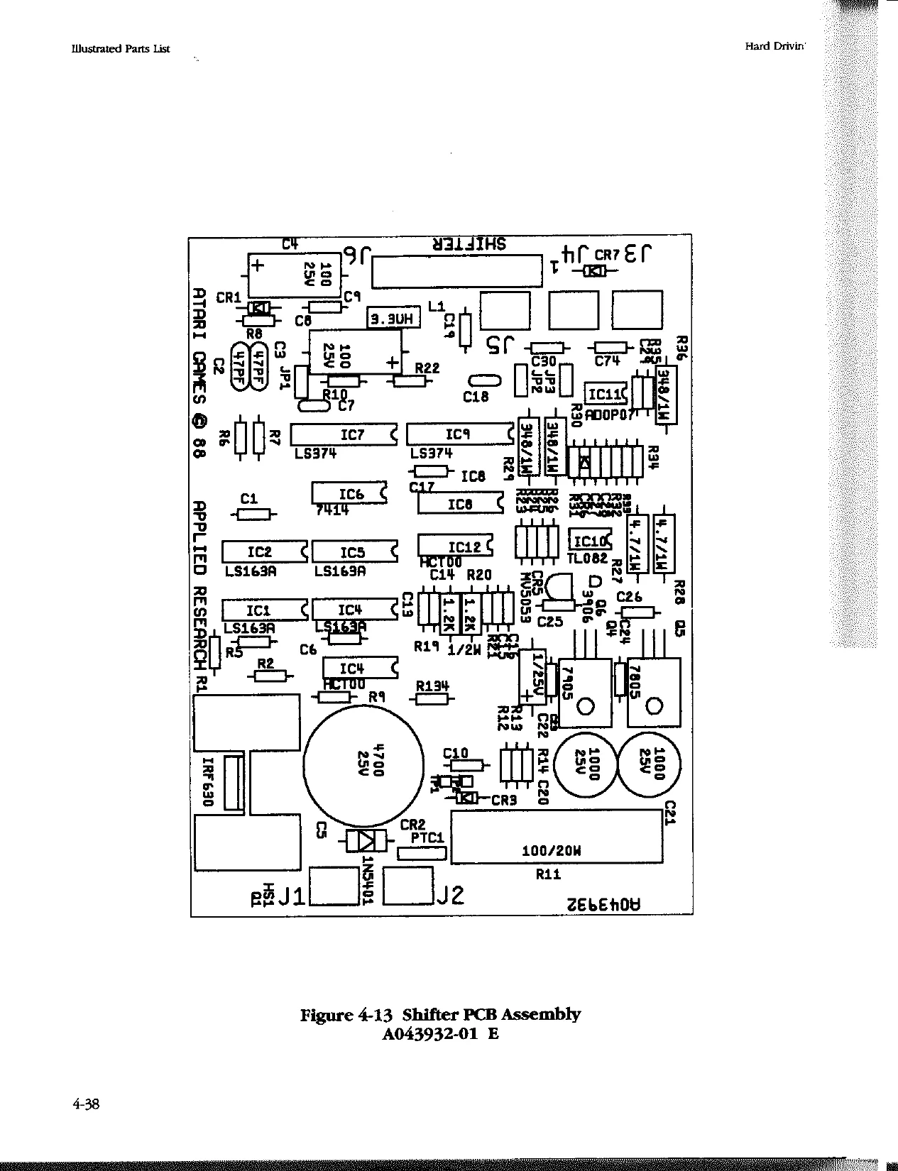
This page is a drawing, shown as the original scan.
Shifter PCB Assembly Parts List
| Designator | Description | Part No. | Designator | Description | Part No. |
Capacitors Transistors
| C1 | Capacitor, .1 lE, 50 V, Ceramic | 122002104 | Q1._— | Transistor, FET, IRF630 | 133039-001 |
| C2, C3 Capacitor, 47 pF, 100 V, Mica | 128002-470 | Q4_Integrated Circuit, 7905 | 137581-001 | ||
| C4 | Capacitor, 100 pF, 25 V, Electrolytic | 124010-107 | Q5_—sIintegrated Circuit, 7805 | 137596-001 | |
| C5 | Capacitor, 4700 uF, 25 V, Electrolytic, | 123021-478 | == Q6_— | Transistor, 2N3906 | 133040-001 |
Radial Resistors
| C6 | Capacitor, .1 pF, 50 V, Ceramic | 122002-104 | R1 | Resistor, 100 K Q, 45%. 1/4 W | 110000-104 |
| C7 | Capacitor, 100 pF, 100 V, Ceramic | 122016-101 | R2 | Resistor, 270 @, 45%, 1/4 W | 310000-271 |
| C8 | Capacitor, 100 UF, 25 V, Electrolytic | 124010-107 | RS—éResistor, | 1K 92, 45%, 1/4 W | 310000-102 |
| C9, C10Capacitor, .1 WF, 50 V, Ceramic | 122002-104 | R6, R7_ Resistor, 510 Q, 45%, 1/4 W | 410000-511 | ||
| €13-C17_ | Capacitor, .1 HF, 50 V, Ceramic | 122002104 | Rg | —_=Resistor, 10 K 92, 45%, 1/4 W | 110000-103 |
| C19 ~~ Capacitor, .1 UF, 50 V, Ceramic | 122002-104 | RO | Resistor, 1 K , +5%, 1/4 W | 110000-102 | |
| C18 | Capacitor, 100 pF, 100 V, Ceramic | 122016-101 | RIO | Resistor 2.2 K O, 45%, 1/4 W | 110000-222 |
| C20, C21 Capacitor, 1000 uF, 25 V, Electrolytic, | 123003-108 | Ri | Resistor, 100 Q, 15%, 20 W (Acceptable Substitute is | ||
| Radial | part no. 116027-101) | 116025-101 | |||
| 22 | Capacitor, 1 pF, 50 V, Electrolytic | 124001-105 | Ri2_—Resistor, 68 K Q, #5%, 1/4 W | 110000-683 | |
| €23-C30, C74 Capacitor, .1 BF, 50 V, Ceramic | ——-122002-104 | R13, R14 Resistor, 10 K Q, £5%, 1/4 W | 110000-103 |
R19, R20. Resistor, 1.2 K , +5%, 1/2 W 110001-122
| Diodes | R21 | Resistor, 22 K Q, £5%, 1/4 W | 110000-223 | |
| CRI | Diode, 1N4001 | 131048-001 | ||
| CR2_ | Diode, 1N5401 | 131051-002 | —-R22_—séResistor, 2.2 KO, 45%, 1/4 W | 110000-222 |
| €R3.—- | Diode, 14005 | 131048-005 | -R23._—_—Resistor, 4.7 K Q, 45%, 1/4 W | 110000-472 |
| CRS | Diode, MV5053, Light Emitting | 131027-002 | «R24, R25__Resistor, 3 K Q, £5%, 1/4 W | 110000-302 |
| R26 | Resistor, 330 2, £5%, 1/4 W | 110000-331 | ||
| €R6 | Diode, 1N100 | 131053-001 | : | |
| CRT | Diode, 1N4001 | 131048-001 | R27, R2B- Resistor, 4.7 2,1 W | 110030-047 |
R29, R30. Resistor, 348.2, 1 W 11029-3480
| Integrated Circuits | R31 | Resistor, 1 K 2, 45%, 1/4 W | 110000-102 | ||
| ICI, IC2 | Integrated Circuit, 7415163 A | 137114-001 | R32___Resistor, 47 K O, 25%, 1/4 W | 110000-473 | |
| IC3_ | Integrated Circuit, 74HICTOO | 137606-001 | |||
| IC4, ICS | Integrated Circuit, 7415163 A | 137114-001 | —-R33_—Resistor, 100 2, £5%, 1/4 W | 110000-101 | |
| 1C6 | Integrated Circuit, 7414 | 137017-001 | -—-—-R34_—_—Resistor, 39 K Q, £5%, 1/4 W | 110000-393 | |
| R35 | Resistor, 2.2 Q, 45%, 1/4 W | 110000-022 | |||
| IC7__ | Integrated Circuit, 7415374 | 137144-001 | R36_—_—Resistor, 348 2,1 W | 10029-3480 | |
| Ic8 | Integrated Circuit, DAC-08 | 137159-001 | |||
| IC) | Integrated Circuit, 7415374 | 137144-001 | R37_—_—Resistor, 2.7 K Q, $5%, 1/4 W | 110000-272 | |
| IC10 | Integrated Circuit, TLO82CP | 137584001 | -R134_ | Resistor, 0 2, 5%, 1/4 W | 110005-001 |
a‘ Miscellaneous
| IC11 | Integrated Circuit, ADOPO7CN | 137523-001 | |||
| ICI2 | Integrated Circuit, 74HCTOO | 137606-001 | ---HS1_—-Heatsink, TDA2030 | 178190-032 | |
| Li | Inductor, 3.3 pH | 141023-001 | -JP1-3. | Connector, Rept, 2 Ckt | 179178-002 |
| JLJS | Connector, 3 Circuit, Header, .156 Ctr | 179213-003 | |||
| Fuse | J6 | Connector, 26 Circuit, Header, .1X . | 179261-026 | ||
| PTC1 | Fuse, Current, PTC, 9 A, 50V | 146011 | 1 Dual |
" 090. 3p14P3 Connector, 3 Ckt, Header, .100 Ctr 179048-003
Ilustrated Parts List Har Dxiein.
OPALI4
82, 1/2W
10UF, 20V
330, 1/2W
Figure 4-14 Brake PCB Assembly A044817-01 F
Hard Drivin’ ‘IWustrated Parts List
Brake PCB Assembly Parts List
| Designator | —Description | PartNo. | | Designator | _—Description | - | Part No. |
Capacitors Resistors
| C1 | Capacitor, 1000 nF, 25 V, Electrolytic | 24-250108 | -R1_—=Resistor, 10, +5%, 1/4 W | 110000-100 |
| ce Capacitor, .1 pF, 50 V, Ceramic | 122002-104 | —-R3_—_—séResistor, 330 O, 45%, 1/2 W | 110001-331 | |
| Capacitor, 470 pF, 25 V, Electrolytic | 123009-477 | «-R4_—éResistor, 1 K Q, 45%, 1/4 W | 110000-102 | |
| 7 Capacitor, .1 F, 50 V, Ceramic | 322002-104 | -RS_—é#Resistorr, 2.2 M 2, 45%, 1/4 W | 110000-225 | |
| 8 | Capacitor, 10 pF, 20 V, Tant | 427001-106 | -R6-_—«#Resistor, 1 K Q, £5%, 1/4 W | 4110000-102 |
| © | Capacitor, .001 UF, 50 V, £10% | 122015-102 | -R7_—séResistor, 10 K ©, 15%, 1/4 W | 110000-103, |
| C10 | Capacitor, .1 pF, 50 V, Ceramic | 122002-104 | -R8_Ressistor, 1 K ©, +5%, 1/4 W | 110000-102 |
| RO | Resistor, 270 K Q, 45%, 1/4 W | 110000-274 |
Diodes
| CR1 | Diode, 1N4740, 10 V, 5%, Zener | 131009213 | RIO-RI2_ | Resistor, 1K 0, 45%, 1/4 W | 110000-102 |
| CR2 | Diode, MV5053, Light Emitting | 131027-002 | |||
| Integrated Circuit | ji | Connector, 9 Circuit, Header, | 179213-009 | ||
| ICl___ | Integrated Circuit, OPAI11 | 137576-002 | 156 Cur, Key 3 |
Transistor
| Ql | Integrated Circuit, 7812 | 137597-001 |
Hard Drivin’ Statistics Sheet
Auto Gagees: Error Count: Total Games:
Laps by Track: Xtended Games by Track: No X Games by Track:
of Games Time No. of Games
| 280-299 | —_——_ | 380-399 | |
| 300-319 | —_— | 400-419 | — |
| 320-339 | ——_. | 420-439 | ——_ |
| 340-359 | = | 440-459 | —_— |
360-379
poe
ATARI
GAMES
Atari Games Corporation 675 Sycamore Drive P.O. Box 361110 Milpitas, CA 95035