VS UniSystem Kit Pac MsPac
PAC-MAN and MS. PAC-MAN (Nintendo, 1985) · Manual · 34 pages · 26 sections · original scan
VS. UniSystem
KIT MANUAL
FOR INSTALLATION IN
PAC-MAN™ ano MS.PAC-MAN™
UPRIGHT VIDEO GAME CABINETS
©1985 Nintendo’ of America Inc. * TRADEMARKS OF BALLY MIDWAY Mra. Co.
WARNIN
This kit should only be installed by a qualified service technician.
TABLE OF CONTENTS
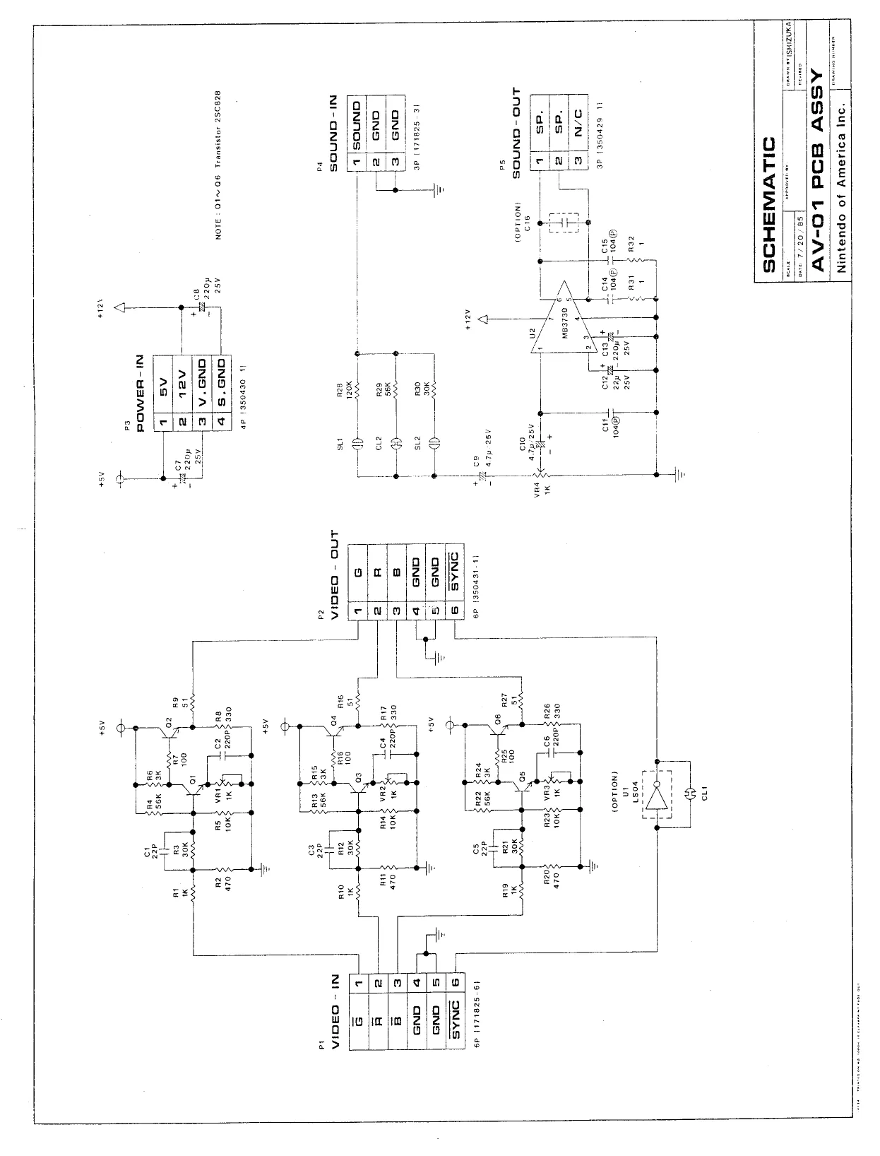
|, Introduction 00... 00 oes ee eee ester e eee te nesses eres s sss il. Contents of VS. UniSystem™ Kit 7 : : lll. List of Tools Needed ie IV. Replacement Process ...-.-.---- +> V. Final Check Sheet and Adjustments VI. Wiring Diagram... --.--- 22-05 PCB Schematics....--- FCC PCB Schematics ...- Power Supply Schematics ... AV-01 PCB Schematics. . . Vil. Reorder Parts Lists ©... 0.00200 s esse reer reer rnsenes
I]. INTRODUCTION
VS. UniSystem™ Kit
The VS. UniSystem™ kit enables you to change any Pac-Man* or Ms. Pac-Man” into a VS. UniSystem™ which will use any non-interactive VS.-Pak®.
Before you begin, be sure you are properly prepared. Make certain you have selected the proper VS. UniSystem™ kit for the particular game you are replacing. Thoroughly read this instruction manual to familiarize yourself with the proper procedures. Make certain that you have all the tools necessary to complete the process.
This kit should only be installed by a qualified service technician.
If you have any questions, please call Nintendo Service at 1-(800)-633-3236.
*trademarks of Bally Midway Mfg. Co.
ll. CONTENTS OF KIT
Parts Name Quantity Remarks
| MDS-GPU PC. Board Assy | 1 | without EPROM’s and custom |
chip
| AV-01 P.C. Board Assy | 1 | includes four (4) OL-E3 P.C. |
Board spacers and four (4) M-3 x 8 machine screws
Power Transformer Assy PT-1321A 1
Power Supply Unit PP-1300A 1
MGS-PM Front Screen 1
MGS-PM Name Plate 1
MGS-PM Control Panel Assy 1
MGS-UP Side Decal 2
MGS-PM VS. UniSystem™ Kit Manual 1
| 062 Shield Cover Complete Assy | 1 | with short 36P and 44P |
harnesses
054 Shield Cage 1
072-PM-36P-44P Edge Harness Assy 1
072-PM-3P Speaker Harness 1
072-PM-6P Video Harness 1
072-PM-4P 600 Service Harness 1
072-PM-01 Ground Harness 1
| 072-PM-02 Ground Wire | 1 | for speaker |
072-PM Monitor Mounting Bracket 2
072-PM Front Screen Bracket (Upper) 1 072-PM Front Screen Bracket (Lower) 41 072-PM Front Screen Support 2
MGS-PM Hole Template 1
Velcro Dot Hook 4
Velcro Dot Loop 4
072 Monitor Bezel
Il. CONTENTS OF KIT (continued)
Parts Name Quantity Remarks
072-PM Operation Panel Support 2
072-PM Operation Panel Retainer 1
MGSK-P Serial Number Plate 1
FCC Class A Label 1
FBI Sticker 1
Power Switch Caution Label 1
| M6 x 30 Carriage Bolt | 6 | for mounting monitor brackets |
| M6 Cap Nut | 6 | for mounting monitor brackets |
| Machine Screw M4 x 10 | 3 | for mounting power supply |
and ground
| Round Head Wood Screw 3.5 x 13 | 48 | 9 pcs FCC cage |
5 pcs front screen bracket (U) 5 pes front screen bracket (L) 8 pcs front screen supports 6 pcs operation panel supports 4 pcs operation panel retainer 5 pcs 072-PM-36P-44P edge harness assy. Screw tie downs - 4 pes AV-01 PC Board 2 pcs extra
| Round Head Wood Screw 3.1 x 10 | 4 | for mounting serial number |
plate
| Round Head Wood Screw 3.8 x 16 | 4 | for mounting PT-1321A |
transformer
| M5 Flat Washer | 4 | for mounting monitor |
| M5 Cap Nut | 4 | for mounting monitor |
| T18R Cable Tie | 2 | For video cable |
| Wire Nut | 3 | for speaker harness and |
ground modification
lll, LIST OF TOOLS NEEDED
Flat Head Screw Driver
Phillips Head Screw Driver
40mm Nut Driver
41/32” Nut Driver
Crescent Wrench
4/4” Drill Bit
Electric Reversing Drill
Phillips Bit for Drill
Staple Gun Alcohol/Cleaner
Wire Cutters
Star Driver or Vise Grips
Solder Iron
IV. REPLACEMENT PROCESS
- Removal of Monitor
Remove the old control panel, front screen and name plate.
- Bezel Supports Removal — Ms. Pac-Man* Only
A. Remove bezel supports from the monitor frame one at a time, retightening monitor frame bolts after removal of each support.
- Remove the Monitor Mounting Supports
A. Ifthe game has metal monitor supports, remove them from the side panels. B. If the game has wooden supports that are wider than 11/4”, cut a notch into the wood as illustrated. (See Illustration 1-2.) The notch should be 3/8” deep. This will allow the clearance for the monitor frame when mounted in a horizontal position.
- Remove Old PC. Board and Main Wire Harness
A. Remove the main wire harness and cut wires from power transformer for Pac-Man*. For Ms. Pac-Man* cut wires between fuse block and transformer. (See Illustration 1-1.)
CONNECTOR FOR COIN LAMPS REMOVE
}
CUT AND REMOVE THESE WIRES)
REMOVE 6 WIRES THIS SIDE
Ms. Pac-Man* 1-1 Pac-Man*
*trademarks of Bally Midway Mfg. Co.
- Mounting Monitor and Front Screen Supports
A. Using template provided, mark and drill three (3) 1/4” holes for the monitor support brackets in both cabinet side panels.
the template. C. Install front screen supports using eight (8) 3.5 x 13 round head screws. (See
Mlustration 1-2.) D. Install front screen retainer upper using five (5) 3.5 x 13 round head screws.
support.
Top of control panel to top of control panel bracket Front screen Upper, Lower and (em se orackels MUST ire ub
Mark locations for screws and install front screen supports. BandC ~
Drill holes at locations ‘A shown on template
b ’ FCC CAGE
1-2
*trademarks of Bally Midway Mfg. Co.
- Side Sticker Application
A. At this time, paint the cabinet a light gray, MAKING SURE TO REMOVE ALL PREVIOUS TRADEMARKS, LOGOS, AND ARTWORK ON THE CABINET. B. Install the side stickers. (See side sticker application sheet Page 13.)
- Installation of Monitor Mounting Brackets
A. Install the monitor mounting brackets using six (6) M6 x 30 carriage bolts and M6 cap nuts. (See Illustration.)
- Installation of Monitor
A. Reinstall monitor in horizontal position using the four (4) M5 flat washers and M5 cap nuts and reconnect the ground harness.
- Installation of FCC Cage
A. Before installing FCC Cage move wooden transformer base to the right of the cabinet as shown in the photograph. (See Illustration 1-3.) B. Install the FCC cage at the angle shown using nine (9) 3.5 x 13 round head wood screws. (See Illustration 1-2.) The FCC cage must be mounted on left side of the cabinet as you look at the back of the cabinet. (See Illustration 1-3.)
- Installation of Power Transformer Assembly and Power Supply
A. Screw down power supply to mounting bracket on side of FCC cage using two
- M4 x 10 machine screws. (See lilustration 1-3.) B. Fasten new power transformer assembly to bottom of cabinet in Icoation shown using four (4) 3.8 x 16 round head screws. (See Illustration 1-3.)
- Installation of AV-01 Interface P.C. Board Assembly
A. Install AV-01 interface p.c. board assembly to the side panel approximately 12 inches above the FCC cage, using four (4) 3.5 x 13 round head wood screws. (See Illustration 1-3.) Note: Feet should point out.
- Installation of MDS PC. Board and Shield Cover Assembly
A. Connect short 44 pin and 36 pin harnesses from the shield cover assy to the MDS p.c. board. B. Slide MDS p.c. board into the slot in FCC cage. C. Fasten the shield cover assy into place using the push-in clasps.
MS. PAC-MAN"
AV-01 PC BOARD
SHIELD COVER ASSY
Pc 3 FCC NEW POWER BOARD § - CAGE TRANFORMER { PP-1300A (PT1321A) POWER SUPPLY
PAC-MAN‘
paver NEW POWER
ASSY | 4 TRANFORMER : 3 ot - (PT1321A)
1-3
“trademarks of Bally Midway Mig. Co. FCC PP-1300A PACE DAWER CIIPPIY
- Installation of Ground Cable and Speaker Ground Cable
A.
B. Fasten the speaker ground cable to one of the speaker mounting screws. (See Illustration 1-4.) Choose one of the longer leads on the main ground harness and fasten to the FCC shield cage along with the other end of speaker ground cable. (Use the one
- remaining M4 x 10 machine screw.) (See lilustration 1-4.) . Fasten the other long lead to one of the 3.8 x 16 mounting screws on the transformer base. (See Illustration 1-4.) Fasten the other three leads to a good metal contact on the coin door, operation panel clamp and service switch. (See Illustration 1-4.)
Control Panel clamp (left side) 4 \ pp Service Switch (RS Coin Door @ /
Speaker 6.5 if | // |
Power Trans. © Va \ / F~— concenitxos —\\ ae ~ a J vee Cage
OZ a
Attach Ground Wire Here SSD) FCC Cage ~
- Installation of Main Wire Harness and Power Transformer
mo Oo BP Connect the Main Harness as shown. (See Illustration 1-5.) Solder the service harness to the service switch before connecting to the main harness. Connect the speaker harness to the speaker by cutting existing speaker wire and using the wire nuts provided or solder directly to the speaker. Connect the power transformer to the power supply and existing power harness connectors. (See Illustration 1-6.) Using five (5) 3.5 x 13 round head screws, fasten the main wire harness to the side panel through the screw down cable ties.
44 pin Edge Connector
rel 5 Volts
Coin Door 9 pin Connector
16 4/1
MDS-CPU D3 P.C. Board
- 2\2 Coin Counter with Diode
Q10
Black Wire to Pin #1 ower Cord
Monitor
Speaker = _Red Wire to
la Pin #1
AV-01 P.C.B, cower Sunol 7 coin Chute taht (Ms. PAC-MAN’ only)
Ce Service Switch 1-5 2
*trademarks of Bally Midway Mfg. Co. 40
- Installation Monitor Bezel
A.
- Installation of the Front Screen and Name Plate Attach the four (4) velcro dot hooks to the monitor corners. Then attach the four
- velcro dot loops to the hooks. Peel off the adhesive backing on the velcro dot loops and attach the monitor bezel. (See Illustration 1-8.)
A. Install the new name plate. _
17. Installation of New Control Panel — Overlay
and Operation Panel Supports Name Plate
A. If you are converting Ms. Pac-Man", remove the old control panel side supports and save the old operation panel clamps. Reinstall the old clamps after installing the new operation panel supports. B. Place the new control panel into the game and draw a line where the top of the control panel meets the side panel wall. (See Illustration 1-2.) C. Measure down from this line 1/16” and mount the new control panel supports parallel to the upper line. (See Illustration 1-2.) D. If you are converting Ms. Pac-Man", remount the control panel clamps directly to the wooden side panel. E. Connect operation panel to the main harness connectors and clamp down. F._ If necessary, use locking pliers to bend the control panel clamps in or out to get the proper tension to secure the control panel.
- Attach Serial Number Plate, FCC Class A Label, FBI Sticker, and Power Switch
mo oO OP
*trademarks of Bally Midway Mfg. Co. Remove all old labels and serial number plates. Using four (4) 3.1 x 10 round head screws provided, attach the new serial number plate in location shown. (See Illustration 1-10.) Adhere the FCC Class A label and staple all four (4) corners in the locations shown. (See Illustration 1-10.) Adhere the new FBI sticker and staple all four (4) corners in the locations shown. (See Illustration 1-10.) Adhere the power switch caution label to the location shown and staple all four corners. (See Illustration 1-10.)
Power Switch —ar Label
ap No. Plate
CEES FCC Labe!
a a Label REMOVE ALL old labels. “ald
ESD C5
Side Decal Application
Step 1.
Start by peeling the protective backing “A” down about 6 inches from the top. Place decal in desired position. Pull down slowly the remainder of the Protective backing of “‘A.’”
While doing this, use a soft cloth to smooth decal onto side board, moving from top to bottom of decal.
Step 2.
Fold remaining decal back, exposing the unprinted side. Begin to peel protective backing “B” from center to right hand side “slowly.” Using soft cloth smooth decal onto side Panel by running hand from top to bottom of decal, moving outward to the right hand side.
Front View
Li
V. FINAL CHECK SHEET AND ADJUSTMENTS
1, FBI sticker installed (MANDATORY) _ New serial number plate installed (MANDATORY)
3, New FCC label installed (MANDATORY) . Power switch caution label installed (MANDATORY)
- PC. Board adjustments made (see PC. Board adjustments page 15)
- Monitor adjustments made (refer to service manual)
- AV-01 adjustments made
- Coins give credit
- Controls on operation panel functioning
{1 10. Sound checked
(J 11. Nameplate lamp is functioning (0 12. All previous trademarks, logos and art work have been removed
AV-01 ADJUSTMENTS
VR1, VR2 and VR3 adjust color level output of interface p.c board. VR4 adjusts volume level output of interface p.c. board
Adjustments
After powering up the game, you will probably find that the screen’s horizontal width is too narrow and the vertical height is too small. To make adjustment to the horizontal width and vertical height, refer to the service manual for your particular monitor.
MDS P.C. Board
~LSJo~ LI LU °°
SWI Swe
Component Side
Cautions: (1) Since the Dip Switch settings (SW2 only) may be changed by new game software, refer to the new game instructions in Operation Manual for VS. Pak®.
- Do not touch the fixed variable resistors (VR1, VR2, VR3, VPB4, VRS, and VR6), as they have already been preset and do not need adjustment.
- If, however, color does not look correct, VR3, VR4, and VR6 may be adjusted in addition to the color adjustments on your monitor and on the AV-01 PC Board.
Vil. REORDER PARTS LIST
BODY PARTS
PART NO. DESCRIPTION
MGSP-01-23 072-PM Front Screen MGSP-01-24 072-PM Name Plate MDST-21-11 MDS-CPU PC. Board Assy. MGSP-AV-01 Audio/Video Interface P.C. Board Assy. MGSU-11-23 Side Decal MGS-UP MGSP-23-61 VS. UniSystem™ Kit Manual - PM CHPU-01-01-10 MDSU-01-01-11 MDSU-01-01-12 MDSU-01-01-13 MGSP-01-50 MGSP-01-69 MGSP-01-53 MGSP-11-10 MGSP-11-11 MGSP-01-48 MGSP-09-01 MGSP-08-00 MGSP-01-67 054 Shield Cage 062 Shield Cage Cover 062-44P FCC PC. Board Assy. 062-36P FCC PC. Board Assy. 072-PM Monitor Mounting Bracket 072-PM Front Screen Bracket (Upper) 072-PM Front Screen Bracket (Lower) 072-PM Front Screen Support 072-PM Operation Panel Support 072-PM Operation Panel Retainer Power Transformer Unit PT-1321A Power Supply Unit PP-1300A 072-PM Monitor Bezel
Operation Pane! Assembly ITEM PART NO. DESCRIPTION
| 1 | MDSF-14-12 | 8 Way Control Lever Assembly |
| 2 | TKGU-23-21 | Switch Collar |
| 3 | TNX-23-18 | 8 Way Guide Plate |
| 4 | TKGU-23-17 | Switch Spacer |
| 5 | TKGU-23-16 | Bearing Brkt |
| 6 | TKGU-23-20 | Spring Stopper |
| 7 | TKGU-23-22 | Lever Spring |
| 8 | TKGU-23-23 | E-Ring |
| 9 | TKGU-23-13 | Micro Switch |
| 10 | TMAU-12-15 | Lever Plate |
| 11 | TMAU-12-14 | Control Knob Plate |
| 12 | TMAU-12-16 | Control Knob Collar 8L |
| 13 | TMAU-1 1-18 | Knob with Shaft 80.5L |
| 14 | MGSP-01-22 | Operation Panel Base w/Overlay |
| 15 | TKGU-23-12 | Switch Button Bracket |
| 16 | TMAU-34-18 | Micro Switch VL 12L (Straight) |
| 17 | MDSU-12-17 | Black Sponge, 2 x 10 x 580L |
| 18 | TKGU-23-26 | Nut Plate |
| 19 | TKGU-23-34 | Pal Nut M16 |
| 20 | MDST-12-21 | Button Assembly (Black) |
| 21 | MDST-12-17 | Button Assembly (Crimson) |
| 22 | MGSP-01-31 | Operation Panel Fastener 072K-P2 |
| 23 | TMAU-12-18 | Collar - 34 x 28 x 7H |
| 24 | MDST-12-24 | Button Assembly (Light Blue} |
| 25 | MDS¥F-12-27 | Button Assembly (Green) |
vs. UniSystem” Operation Panel Assembly Parts (Upright)
5-3
Operation Panel Assembly
WIRING HARNESSES PART NO. DESCRIPTION
MGSP-41-15 072-PM-36P-44P Main Edge Harness Assy MGSP-13-01 072-PM-3P Speaker Harness MGSP-13-02 072-PM-6P Video Harness MGSP-13-03 072-PM Ground Harness MGSP-13-04 072-PM Ground Wire MGSP-13-05 072-PM-4P-600 Service Harness MDSU-41-11 36P-062 FCC Harness MDSU-41-12 44P-062 FCC Harness MDSU-42-11 C-062-15P Main Switch Harness MDSU-42-12 C-062-12P Sub Switch Harness
MDS P.C. Board Assembly (continued) PART NO. DESCRIPTION (Reference Designations and Locations)
| MDST-21-49 | 10K 21/4W + 5% Resistor | (R3, RS, R7, R16, R18, R19, R21, R33, R56 |
R63, R75, R82, R83, R85, R86, R120)
| MDST-21-50 | 12K 21/4 W + 5% Resistor | (R76, R96, R98) |
| MDST-21-51 | 20K 2 1/4W + 5% Resistor | (R94, R99) |
MDST-21-52 33K 21/4W + 5% Resistor (R1, R2) MDST-21-53 100K 2 1/4W + 5% Resistor (R10, R35, R84, R103, R121)
| MDST-21-54 | 150K Q 1/4W + 5% Resistor | (R74, R118) |
| MDST-21-55 | 360K 21/4 W + 5% Resistor | (R107, R114) |
MDST-21-56 750K 21/4W + 5% Resistor (R101, R108, R109, R110, R115, R116) MDST-21-57 1M 21/4W + 5% Resistor (R102, R106, R112, R117)
| MDST-21-58 | 1.8M 2 1/4W + 5% Resistor | (R90, R105) |
| MDST-21-59 | 2.2M 21/4W + 5% Resistor | (R81, R87, R100, R104) |
| MDST-21-60 | 1K Q x8 Series Resistor Array | (RM1, RM2, RM5, RM8, RM11, RM14, RM17) |
MDST-21-61 68 2x 4 Parallel Resistor Array (RM3, RM4, RM6, RM7, RM9, RM10, RM12, RM13, RM15, RM16)
| MDST-21-62 | 33pF 50V Ceramic Disc Capacitor | (C35, C91, C92) |
| MDST-21-63 | 68pF SOV Ceramic Disc Capacitor | (C25, C86) |
| MDST-21-64 | 100pF 50V Ceramic Disc Capacitor | (C38, C42, C43, C46) |
| MDST-21-65 | 220pF 50V Ceramic Disc Capacitor | (C26 ~ 29, C34, C45) |
| MDST-21-66 | 0.01 p F 50V Ceramic Disc Capacitor | (C9, C10, C89, C90) |
| MDST-21-67 | 0.1 p F 25V Ceramic Disc Capacitor | (C100 ~ C178) |
| MDST-21-68 | 0.2 # F 12V Cerarnic Disc Capacitor | (C4, C12) |
| MDST-21-69 | 0.047 p F 50V Film Capacitor | (C37, C39, C40, C44) |
| MDSTF-21-70 | 3.3 u F 16V Al. Electrolytic Capacitor | (C15 ~C18, C31, C32) |
| MDST-21-71 | 10 pF 16V Al. Electrolytic Capacitor | (C3, C5, C6, C11, C13, C14, C19 ~ C24, C30, |
C33, C36, C41, C47 ~ C85)
| MDST-21-72 | 47 » F 16V Al. Electrolvtic Capacitor | (C2) |
| MDSTF-21-73 | 100 p F 16V Al. Electrolytic Capacitor | (C1) |
| MDST-21-74 | 100 # F 25V Al. Electrolytic Capacitor | (C8) |
| MDST-21-75 | 470 u F 16V Al. Electrolytic Capacitor | (C7, C87, C88) |
| MDS¥F-21-76 | 500 & Variable Resistor. Red Cap | (VR1, VR3) |
| MDST-21-77 | 500 © Variable Resistor. Green Cap | (VR2, VR4) |
| MDST-21-78 | 500 2 Variable Resistor. Blue Cap | (VRS, VR6) |
| MDST-21-79 | 21.47727MHz Crystal | (X1) |
| MDST-21-80 | 8 position dip switch | (SW1, SW2) |
| MDST-21-81 | 28P IC socket | (1A, 1B, 1C, 1D, 2A, 6A, 6B, 6C, 6D, 8A, 8B) |
| MDST-21-82 | 40P IC socket | (2F, 2J, 8F, 8d) |
MDST-21-83 Type 32-4 (UMS x 2) Battery Case MDST-21-84 Bolt with washer M2.6 MDST-21-85 Flat washer M2.6 MDST-21-86 Nut Plate M2.6 MDST-21-87 Dry Battery “AA” T18L Beaded tie
MDS P.C. Board Assembly PART NO. DESCRIPTION (Reference Designations and Locations) MDST-21-11 P.C. Board Assembly
| MDST-21-12 | 2A03 Microprocessor | (2J,8J) |
| MDSTF-21-13 | HM6116 2k x 8bit Static RAM, 250ns | (6E) |
| MDST-21-14 | MB8416-15 2k x 8bit Static CMOS RAM 150ns | (8L) |
| MDST-21-15 | TC5533P-A 4k x 8bit Static RAM | (2C) |
| MDST-21-16 | TC5533P-B 4k x 8bit Static RAM | (8C) |
| MDST-21-17 | 74LS00 Quad 2-input NAND LS TTL | (4C, 5C) |
| MDST-21-18 | 74LS04 Hex Inverters LS TTL | (IL, 2K, 4E, 5E) |
| MDST-21-19 | 74LS10 Tri 3-input NAND LS TTL. | (4D) |
| MDST-21-20 | 74LS32 Hex 2-input AND LS TTL | (4A, 4B, 5A, 5B) |
| MDST-21-21 | 74LS74 Dual D-Flip Flops LS TTL | (5D) |
| MDST-21-22 | 74LS123 Dual Retriggable Single Shots LS TTL | (1J) |
| MDSTF-21-23 | 74LS138 Dual 2 to 4 Demultiplexers LS TTL | (1F, 6F) |
| MDST-21-24 | 74LS157 2 to 1 Data Selectors LS TTL | (5J, 5K, 6J, 6K) |
| MDST-21-25 | 74LS165 8bit Shift register LS TTL | (6M, 6N, 7P, 8P) |
| MODST-21-26 | 74LS240 Octal 3 State Bus. Inverters LS TTL | (7M, 7N, 8M, 8N) |
| MDST-21-27 | 74LS245 Octal 3 State Bus Transceivers LS TTL | (3K, 8K) |
| MDST-21-28 | 74LS373 Octal 3 State D-Latchs LS TTL | (2E, 8&) |
| MDST-21-29 | 74F04 Hex Inverters FAST TTL | (5H) |
| MDST-21-30 | 4066 Quad Analog Switches C-MOS | (2P, 4P) |
| MDST-21-31 | LM324 Hex Operational Amplifiers | (IP, 3P) |
| MDST-21-32 | LM3900 Hex Operational Amplifiers | (5N, 5R) |
| MDST-21-33 | PST518A Reset IC | (1K) |
| MDST-21-34 | 2SA933 Silicon PNP Transistor | (Q3, Q7, Q13 ~Q16, Q19 ~ Q22, Q26, Q27) |
MDST-21-35 28C1740 Silicon NPN Transistor (Q1, Q2, Q4~ Q6, Q8, QY, Q12, Q17, Q18, Q23 ~ Q25) MDST-21-36 2SD592 Silicon NPN Transistor (Q10, Q11) MDST-21-37 18953 Silicon Switching Diode (D1, D2, DS, D7, D9~ 11)
| MDST-21-38 | W038 Silicon Diode | (D3, D4, D6, D8) |
| MDSF-21-39 | 27 Q1/4W + 5% Resistor | (R4) |
| MDST-21-40 | 33 21/4W + 5% Resistor | (R22, R30, R36, R38, R46 R47, R72, R89) |
MDST-21-41 100 21/4W + 5% Resistor (R79, R80, R95, R97) MDST-21-42 330 21/4W + 5% Resistor (R8, R20, R28, R29, R48, R49, R70, R71, R73, R91)
| MDST-21-43 | 680 21/4W + 5% Resistor | (R119) |
MDST-21-44 1K Q1/4W + 5% Resistor (R31, R32, R92, R93) MDST-21-45 1.2K Q1/4W + 5% Resistor (R37, R43) MDST-21-46 2.2K Q1/4W + 5% Resistor (R6, R11, R12, R14, R16, R23, R24, R27, R39 ~R42, R50, R51, R54, R55, R64, R65, R68, R69, R81, R87)
| MDSF-21-47 | 3.3K | 21/4W + 5% Resistor | (R77) |
| MDST-21-48 | 4.7K Q1/4W + 5% Resistor | (R13, R17, R95, R26, AS2, RES, Ree, RE7} |
Power Supply Parts located on PC. Board 3D-0173
PART No. DESCRIPTION MDSU-08-01 MDSU-08-02 MDSU-08-03 MDSU-08-04 MDSU-08-05 MDSU-08-06 MDSU-08-07 MDSU-08-08 MDSU-08-09 MDSU-08-10 MDSU-08-114 MDSU-08-12 MDSU-08-13 MDSU-08-14 MDSU-08-15 MDSU-08-16 MDSU-08-17 MDSU-08-18 MDSU-08-19 MDSU-08-20 MDSU-08-21 MDSU-08-22 MDSU-08-23 MDSU-08-24 MDSU-08-25 MDSU-08-26 MDSU-08-27 MDSU-08-28 MDSU-08-29 MDSU-08-30 MDSU-08-31 MDSU-08-32 MDSU-08-33 MDSU-08-34 MDSU-08-35 MDSU-08-36 MDSU-08-37 MDSU-08-38 MDSU-08-39 MDSU-08-40 MDSU-08-41 MDSU-08-42 Transistor 2SC2562 or 28C3239 (Q2) Transistor 28C2749 or 2SC2938 (Q3) Photo Coupler* (S22MD1 V) or (TLP541G) (PC1) Photo Coupler (PC614) (PC2) Hybrid IC (30-3000) (IC1) IC (MPC78M24) (IC2) IC (TL431 CLP) (1C3) IC (MPC78M12) (IC4) Transformer (3D-0173) (TR) Choke Coil SC2A (L1) Choke Coil SF-C27-00105-01 (L2) Fuse Holder 0G751-0062 Fuse 3A 125V Resistor 5.1 OHM 5W (Cement) (R1) Resistor 30 OHM 5W (Cement) (R10) Resistor 100 OHM 5W. (Cement) (R16) Resistor 510 OHM 5W. (Cement) (R20) Resistor 20 OHM 5W. (Cement) (R22) Resistor (carbon) 100 KOHM ¥2Ww (R3, 14) Resistor (carbon) 100 OHM Ww (RS) Resistor (carbon) 5.6 OHM Ww (R18, 19, 21) Resistor (carbon) 820 OHM +2Ww (R13) Resistor (carbon) 1 KOHM “Ww (R4, 6. 15) Resistor* (carbon) 47 KOHM or 10 KOHM *%:W (R7) Resistor (carbon) 27 KOHM VW (R8. 17) Resistor (carbon) 100 OHM 1/aw (R9, 11,12, 23, 24) Resistor (carbon) 1.8 KOHM ‘WwW (R25) Resistor (carbon) 2.7 KOHM ‘/aW (R26) Variable Resistor 50 KOHM (VR1) Variable Resistor 2 KOHM (VR2) Film Capacitor 0.047MF 630V (C1,4) Film Capacitor 0.22MF 250V (C10, 28, 29) Ceramic Capacitor 2200PF 2KV (C2,3,11.14,15, 18) Electro Capacitor 330MF 200V (C5) Electro Capacitor 100MF 50V (C16, 24) Electro Capacitor 4.7MF 50V (C7) Electro Capacitor 47MF 35V (C8, 17) Electro Capacitor 100MF 25V (C25) Electro Capacitor 3300MF 10V (C19, 20, 21, 22, 23) Mylar Capacitor 1000PF 50V (C12) Mylar Capacitor 0.01 MF 50V (C6, 9. 27) Mylar Capacitor 0.1MF 50V (C13)
“Note: The 522MDIV uses R7 of 47 KOHM and the TLP541G uses R7 of 10 KOHM
Power Supply (continued) Parts located on P.C. Board 3D-0173 PART NO. DESCRIPTION MDSU-08-43 Mylar Capacitor 0.047MF 50V (C26) MDSU-08-44 Bridge Rectifier S4V840 (D1) MDSU-08-45 Diode 18954 (D3) MDSU-08-46 Diode 181835 (D6, 7, 10, 14) MDSU-08-47 Diode 30DF2 (D11, 15) MDSU-08-48 Diode CTB-33S (D12) MDSU-08-49 Zener Diode RD 5.1EB3 (ZD1, 5.1 Volt) MDSU-08-50 Thyristor 5P2M (Q1) MDSU-08-51 Connector 1 (CON1) MDSU-08-52 Connector 2 (CON2) POWER SUPPLY PC. BOARD 3D-1015S PART NO. DESCRIPTION LOCATION(s)
| MGSP-08-01 | Transistor 2SD571 | TR2 |
| MGSP-08-02 | Transistor 2SC3236 or 2SC2553 | TR1 |
| MGSP-08-03 | Photo Coupler PC 617 | PC |
| MGSP-08-04 | Diode CTU22S | D3 |
| CHPU-88-19 | Diode 1S1835 or 10DF6 | D1, D2 |
| CHPU-88-21 | Zener Diode RDS5.1EB2 | ZD |
| CHPU-88-13 | Voltage Regulator TL431CLP. | IC |
| MGSP-08-05 | Transformer T-12S(100V) | T |
| MGSP-08-06 | Coil 172L2 | L2 |
| MDSU-08-10 | Coil SC2A | Lt |
| MGSP-08-07 | Resistor 47K ohm 2W (cement) | R2 |
| MDSU-08-20 | Resistor 100 ohm 1/2W (carbon) | R3 |
| TKG-08-39 | Resistor 12 ohm 1/2W (carbon) | R12 |
| MGSP-08-08 | Resistor 150K ohm 1/2W (carbon) | R4 |
| MGSP-08-09 | Resistor 150 ohm 1/2W (carbon) | RS |
| MGSP-08-10 | Resistor 1 ohm 1/2W (carbon) | R8 |
| MGSP-08-11 | Resistor 820 ohm 1/2W (carbon) | R17 |
| MGSP-08-12 | Resistor 2.2K ohm 1/4W (carbon) | R7 |
| MDSU-08-20 | Resistor 100 ohm 1/4W (carbon) | R9, 19 |
| MDSU-08-23 | Resistor 1K ohm 1/4W (carbon) | R6 |
| MGSP-08-13 | Resistor 3.3K ohm 1/4W (carbon) | R10 |
| MGSP-08-14 | Resistor 2.2K ohm 1/4W (carbon) | R14 |
| MGSP-08-15 | Resistor 330 ohm 1/4W (carbon) | R13, 14 |
| MGSP-08-16 | Resistor 18K ohm 1/4W (carbon) | R15 |
| MGSP-08-17 | Resistor 3.9K ohm 1/4W (carbon) | R18 |
| MGSP-08-18 | Variable Resistor 2K ohm | VR |
| MGSP-08-19 | Film Capacitor 0.047 mF 630V | C7, 18 |
| MGSP-08-20 | Film Capacitor 470 pF 2KV | C12 |
| MDSU-08-42 | Mylar Capacitor 0.1 mF 50V | C9, 10 |
| MDSU-08-43 | Mylar Capacitor 0.047 mF 50V | C1 |
| TKG-08-21 | Ceramic Capacitor 470 pF 2KV | C8 |
| MGSP-08-21 | Electro Capacitor 1 mF 50V | C17 |
MGSP-08-22 Electro Capacitor 680 mF 16V C13, 14, 15,16 MGSP-08-23 PCB 3D-1015-3 MGSP-08-24 4 Pin Amp Connector
MGS AUDIO-VIDEO INTERFACE PC. BOARD AV-01
| PART NO. | 7 | DESCRIPTION | LOCATION(s)_ |
| TKG-57-03 | TTL 74LS04 (not in Pac-Man* kit!) | U1 | |
| MDST-31-02 | 12W AUDIO AMP MB3730 | U2 |
MDST-31-03 TRANSISTOR 2SC828P or Q Q1,Q2,Q3,Q4,Q5,06
| TKG-57-74 | 1K | OHM Carbon Film Resistor 4W 5% | R1,R10,R19 | |||
| TKG-57-88 | 470 | " | " | a | i" | R2,R11,R20 |
| DJR-57-79 | 30K | . | " | 7 | a | R3,R12,R21,R30 |
| MDST-31-04 | 56K | a | " | ii | " | R4,R13,R22,R29 |
| TKG-57-71 | 10K | " | " | " | " | R5,R14,R23 |
| MDST-31-05 | 3K | " | " | = | " | R6,R15,R24 |
| TKG-59-90 | 100 | " | " | " | ’ | R7,R16,R25 |
| TKG-57-85 | 330 | " | a | " | " | R8,R17,R26 |
| TKG-18-36 | 51 | " | = | " | ” | R9,R18,R27 |
| TPP2-07-60 | 120K | " | " | = | " | R28 |
| MON-11-20 | 1 | " | ° | a | R31,R32 | |
| TKG-57-56 | 22pf | 50V Ceramic Capacitor | C1,C3,C5 | |||
| TKG-56-55 | 220pf | SOV Ceramic Capacitor | C2,C4,C6 | |||
| MON-90-60 | 220uF 25V Electrolytic Capacitor | C7,C8,C13 | ||||
| MON-90-58 | 4.7u4F 25V Electrolytic Capacitor | C9,C10 | ||||
| MDST-31-06 | 22uF | 25V Electrolytic Capacitor | C12 | |||
| TKG-56-58 | 0.14F | 50V Polyester Capacitor | C11,C14 | |||
| MDST-31-07 | 1K OHM 1/5 WATT Variable Resistor | VR1,VR2,VR3 | ||||
| MDST-31-08 | 1K OHM 1/3 WATT Variable Resistor | VR4 | ||||
| MDST-31-10 | Connector 6 Pin AMP EI Straight Type Video In | Pt | ||||
| MDST-31-11 | Connector 3 Pin AMP EI Straight Type Audio In | P4 | ||||
| MDST-31-12 | Connector 6 Pin AMP Mate-n-lock Type Video Out | P2 | ||||
| MDST-31-13 | Connector 4 Pin AMP El Straight Type Power In | P3 | ||||
| MDST-31-14 | Connector 3 Pin AMP El Straight Type Sound Out | P5 |
MDST-31-09 HEATSINK A and B MDST-31-15 BOLT W/WASHER M8 x 10 (4 REQUIRED) MDST-31-00 COMPLETE AV-01
“trademarks of Bally Midway Mfg. Co. 24
PRINTED IN U.S.A.
This page is a drawing, shown as the original scan.
Fuse ies ak t5v ct 0.0873 620v i > a c : elajmi[e{ojolnjoio
ant cs Jt cr seo" any 2o0v ov
PCB 3D-0173
POWER SUPPLY ASSY (PP-1300A
Nintendo of America Inc.
40P Connector 44P Edge Connector
on it ee
Lidtii didi
SCHEMATIC
062 44P FCC PC Board Nintendo of A
i
'
i 40P Connector 36P Edge Connector | i
i ]
}
!
{
SCHEMATIC
36P FCC PC Board
ea Ine,
MDS PCB
062 44P FCC HARNESS A 4 ‘eno aot a4 4 a ‘GNO) ee a 2 ‘GN nes 51s 2 =I ‘GNO tee (508 B 3 13 ae 717 3 c oY, REO ale Cc a ov RED =IES) 4. {=} 3V Teanen 4. Ag. g Tiav grange i 4111)
| E 212V | 1212 | Ee |
F FROWN. | acon aan SS H CONT FED ala H B 'S COIN, REO ass 0 8 J Moon? + RED. 7616) J 3 S AED HED AZZ, a =) K MRED BROWN 48/18) K AG) screen, gout _q 918) (a) I=) L M GREEN ot 2020) L ML aie mun B6ea CO ae S BLUE ORANGE __ S33) Ty ae ORANGE AD N ‘M BLUE UE | IND Mats sync} —SE___leeia5) o fake
| B MsyNC | iBee6) | LP |
aa T aa
| ae | | | To |
Ss Hi eto ores lege gy ‘ORANGE
| | | Se Row Beg | nal |
Uy [i counter seo B29) o AZ
| | | 71S COUNTER | 30 a wo |
- 48) Vv ava Wy |e Seavige >; Seow a asi AS] Ssenvice #42" _gaisey WW) [XX] wsouxo HH} 8383) Bol ssouo__ 4 -- —( x 41 ‘GND eo ow 25S) a ma GND) +r BSS ¥. “Gnd, : Zz GNO. SLACK (338) Zz i
062 36P FCC HARNESS i
| i | SND prow | | |
| | | Si RIGHT} BRU 5 | 2] | |
| | | minGHT ——“Fep 7} & | a |
StLEFT RED 7 3 Mi LER OHANGE ta aicomn ee G 5] | |—_veuwow | re] xeon . YELLOW GREEN | vigwrsiue —}+ fa) 5
| i | a SwitéW }-~icur aus} S93 | a |
i __ MiB Switch — BLUE A616: ro) i
| ij | sseect 1} 1477 | fei | |
Setect1 |}, -—_e Th J) Jf ‘ssetect? |} 4 9419) 3 MSELECT? ora 2oeo a K) sseuecrs +S aia a ats}
| | | MSELEST 2 ——— oC on oe] | a k |
| vs setecrs __}- 4s __pap3i mn Aq} oN Sweet Bapa mM $2 RIGHT, ey 5/25) je) 1 a2 RIGHT, ED 626) ia] iN] | mur} — 8 saeg GC M2 LeeT____ "Grange t i ral sur Ean BIE] 0 aa | i=] me up} __ 30) A As, sz oown {stow 34137 asi
| | | Pee bom cut 32a: | S |
Me) sz a'swirce one ick] 4
| { | Cr wa switcw Saar _13q 34 | CF |
| i | [AZ| "sesmirew tae 535) | Az, |
| | | PU wesswiren eae S36) | UO |
| j | ei ‘GNO Boek 7137) | 18) |
| Vv GND | f=} | Vv |
44P Edge Harness Connector
36P Edge Harness Connector
WIRING DIAGRAM
TE
eae 310184
062 FCC PC Board
Nintendo of America Inc.
& #9 100
uw Fi 49 ~
JAwmi28 as Fa} service
ro. awe rons 32 uF
BEee ote |
ne G
Bs) GMT
te Tar peed
BBs sone,
igo YeeM 3900 ae 42 Sern GND T1FIN
+12 GND 8, Tew
M0S-02-CPU
Nintendo Co.Ltd.
wav 15