F-15 Strike Eagle (090-10000-001)
F-15 Strike Eagle (rev. 2.2 02/25/91, 29K ver. 3.1f) (Microprose Games Inc., 1991) · Manual · 76 pages · 145 sections · original scan
This page is a drawing, shown as the original scan.
FCC WARNING
This equipment has been tested and found to comply with the limits for
a Class A digital device,
pursuant to Part 15 of the FCC Rules. These limits
are designed to provide
reasonable protection against harmful interference when the equipment is operated in a commercial environment. This equipment generates, uses and can radiate radio frequency energy and if not installed and used in accordance with the instruction manual, may cause harmful interference to radio communications. Operation of this
equipment in a residential
area is likely to cause harmful interference in which case the user will be required to correct the interference at his own expense.
Notes and Warnings
Copyright © 1990 by MicroProse Games, Inc. All Rights Reserved.
Reproduction of any part of this publication by mechanical, photographic, or electronic process, or in the form of audio or video recording is strictly and expressly forbidden. In addition, the document may not be stored in a retrieval system, transmitted, or otherwise copied for public or private use, without express written permission from the publisher. The game play, computer code/software, all graphic designs, this technical manual, and its accompanying schematic diagrams are protected by U.S. Copyright. The Copyright Act provides for substantial penalties for those violating federal copyright laws. In such an instance, courts may impound articles believed to be in violation of the copyright while legal action is pending. If Copyright violators are convicted, courts can order destruction of those articles.
In addition, the Act also provides for payment of statutory damages. Violators may also have to pay court costs, attorneys’ fees or fines as well as face imprisonment. MicroProse Game, Inc. will stringently enforce its Copyright against violators. We will use all legal means to immediately halt manufacturing and distribution of any unlawful copies of video games. Those purchasing such unlawful copies risk confiscation of same.
Contents
Chapter 1 Set-up and Operation 1.1 Set Up and Operation 1.2 Control and Switch Location
1.3 Marquee Installation 1.4 Operator's Options
Chapter 2 Options and Diagnostics 2.1 Self Test and Diagnostics Screen 2.1 How to Use Menus
2.2 Operating Menus (table) 2.3 Player Control Test 2.4 Diagnostics Menu Screens 2.5 Collection Audit Menu
2.6 Game Play Statistics 2.7 Game Play Options and Utilities 2.9 Coin Option Menu 2.9 Set Clock and Calendar
2.11 Power- Up Diagnostics (table) 2.12 Sound Board Diagnostics (table) 2.13 Health LED's and Switch Settings 2.14 Major Component Location Diagram 2.15 Major Component Location Diagram 2.16 Notes
Chapter 3 Maintenance 3.1 Maintenance
3.1 Joystick Switches 3.3 Joystick 3.4 Centering Sensor 3.5 Optical Encoder 3.6 Pivot
3.7 Throttle
3.8 Monitor
3.9 Speakers 3.10 Electronics Tray 3.11 Changing the Fluorescent Lamp
3.12 Notes
Table of Contents Continued Next Page
ut) —— e-
Chapter 4 Illustrated Parts List
4.1 Introduction
4.2 Cabinet Assembly 4.3 Cabinet Assembly Parts List 4.4 Front Exploded View 4.5 Rear View
4.6 Rear View
4,7 Electronics Tray 4.8 Power Supply and Power Back Plane Board 4.5 Power Supply Schematic 4.10 joystick Assembly 4.11 Joystick Parts List and Centering PCB Parts List 4.12 Throttle
4.13 Throttle Assembly Parts List 4.14 Marquee Assembly 4.15 Host Processor PCB Component Location Diagram 4.16 Host Processor PCB Parts List
4.17 Host Processor PCB Parts List
4.18 Dr. Math PCB Component Location Diagram 4.19 Dr. Math PCB Parts List
4.20 Dr. Math PCB Parts List
4.21 Video Graphics PCB Component Location Diagram 4,22 Video Graphics PCB Parts List 4,23 Video Graphics PCB Parts List 4,24 Sound Board PCB Component Location Diagram 4.25 Sound Board PCB Parts List
4.26 Sound Board PCB Parts List
4.27 Coin Co Coin Door
4.28 Coin Co Coin Door Parts List 4.29 Wiring Harness and Fuses 4.30 Wiring Diagram 4.31 Wiring Diagram 4.32 Wiring Diagram 4.32 Wiring Diagram 4.33 Wiring Diagram 4.34 Decals
4,35 EPROM and PAL Location Chart
4.36 Notes
4.37 Credits
4.38 Warranty
Safety Checklist
The MicroProse game you have purchased has been designed to meet the stringent standards of various safety agencies. However, transportation of the game may result in physical damage or other mechical compromise to components or connections, that could result in electrical shock or other injuries. Therefore, it is important that you check the following items:
Connections Check AC power and ground connections. Failure to
check these can result in a lethal electrical shock.
Printed Circuit board, Video display, and Control connections must also be checked to insure proper operation and safety.
AC Power Verify that the game is wired for the proper AC voltage. To do that you must check both the voltage selection connectors in the power supply, and the AC voltage selection harness which is located just inside the lower rear access vent (See page 1.1). For safe operation the game should be connected to a grounded three-wire outlet. Inspect the power cord for cuts or other physical damage before connecting it to the outlet.
Fuses Never operate the game with fuses other than those specified on the power supply or in the parts list.
Repairs Before attempting any repair disconnect the power to
the game. If repair to the video display is attempted, be careful, high voltages continue to exist on the display circuitry and the Cathode Ray Tube (CRT).
vi
NOTES
CHAPTER ONE
Set-up and Operation
To insure proper and safe operation of F-15 Strike Eagle™
please check the items listed below before applying power. For additional safety items please review the Safety Checklist found in the beginning of this manual.
Connectors
Please check all connectors before attempting to apply power to the game. Transportation can result in physical damage or other mechanical compromise to various components of the game.
AC Power
Verify that the game is wired for the proper voltage. To
selection harness insure that the game is wired for the proper voltage, you must check both the voltage selection connectors in the power supply, and the AC voltage selection harness, located just inside the lower rear access vent. For safe operation the game
should be connected to a grounded three-wire
outlet, Inspect the power cord for cuts or other physical damage before connection to the outlet.
Power Supply Verify that the power supply is wired for the correct voltage and that the correct fuses are installed. Check the harness connections to the supply to insure that they haven’t come loose.
1.1
1.2
Control and Switch location
Power On/Off Switch The power on/off switch is located on the bottom of the monitor support platform in the right rear of the game.
Volume Control
Access to the volume control is through the upper coin door. The control is on a bracket located in the center of the wood panel. Self-Test Switch The self-test switch is located to the right of the volume control on the utility bracket.
Coin Counter
The coin counter is located behind the lower coin door beneath the cash vault.
Control Panel Latch
To open the control panel you must release the two latches that secure it to the cabinet. To gain access to these, open the upper coin door and reach up to the left and right and release each latch.
Monitor Control Board
F-15 Strike Eagle™ has a separate monitor control board that contains the most commonly used controls. This board allows the operator to adjust the monitor while standing in front of the game. To gain access to this control you must open the contro! panel.
Top Marquee Installation
The supplemental marquee arrives in a separate box. Use the following steps to install it on the game. Carefully unpack the marquee and remove the rear cover by removing 3 screws, one at the top and one at each side.
Remove the sign plate from the plastic housing. Shut off the main power switch.
Remove the 6 screws that secure the attraction
panel, and remove it from the monitor shroud. Remove the 2 plugs from the top of the front monitor shroud. Remove the nuts and washers from the bottom of the 2 threaded nipples. Place the marquee on top of the monitor shroud and insert the 2 threaded nipples through their corresponding holes. Firmly tighten the nuts on the lower end of the nipples to secure the marquee to the monitor shroud. Thread the lamp wires through the lefthand nipple. Plug the 4 pin connector into the socket. 10 Place the sign plate into the marquee housing. Replace the rear cover and secure it with its 3 screws.
11 Screw the upper end of the marquee brace into the center of the rear cover of the marquee.
When mating the connector in step 9 be sure that the green, black and white wires connect to the same color wire on the other connector. Li
1.3
Game Specifications
1.4
Operator Options
To check or change options enter self-test by turning the self-test switch on and selecting the Coin Options or Game Play Options and Utilities screens. Then select the desired sub-menu. To exit self-test turn the selftest switch off.
CHAPTER TWO F-15 Self-Test & Diagnostics Screens
The self-test mode is a series of screens (or “menus”) that enables the operator to check game controls, view game statistics, and make adjustments to the pricing and difficulty. These menus are accessible by moving the self-test switch to the down position (either before power-up or during attract mode).
You may have to press the [START] button after moving the switch down during attract mode.
How To Use The Menus
The first operator menu is the “Main Menu.” Beneath the “Coins Counted Since Reset” text is a group of seven options. The currently selected option is white, with the remaining options blue. To cycle among the options, move the joystick up or down. Press any button on the joystick to choose the currently selected option. Underneath the choices of each menu is a brief explanation of the possible actions.
How To Get Back To Attract Mode You can instantly exit from any menu to attract mode by moving the self-test switch back to the up position.
2.1
Operator Menus Summary
The following table summarizes the functions of F-15’s self-test menus. Items marked with a ‘OY’ should be performed whenever the game is installed on location. Items marked with a ‘/’ may need to be adjusted, depending on the location.
Player Control Test
@ Check coin and input switches. Q Recalibrate throttle limits.
Check sound volume potentiometer. Q Check joystick operation/centering.
Diagnostic Tests
2 Monitor test pattern display. Run sound board test.
Last system error display.
Collection Audit
View coin/time figures. View previous coin/time figures. View detailed “vend history”. Clear coin/time figures. Clear vend history statistics.
Game Play Statistics
View general play information. View tabulation of games played. Q Clear game play statistics.
Game Play Options and Utilities
v¥ Adjust game difficulty setting. v¥ Set lives per credit.
¥ Set minimum sound volume.
Q Restore factory coin and play settings. Reset high scores.
Coin Options v¥ Set coin(s) for play start. ¥ Set coin mechanism multipliers. v¥ Set coin(s) for play continue.
Set Clock and Calendar Q Adjust battery-backed time settings.
THROTTLE RECALIBRATION
VOLUME
ADJUSTMENT
Joystick
(CENTERING
The Player Control Test
This screen presents the status of these I/O devices: Throttle: Potentiometer value (with current limits). Volume: Potentiometer value (ranges from 0-- 255). Switches: State of panel, coin, and joystick switches. Joystick: Value of X and Y encoders. Sensor: “Centered” text color changes to bright yellow when joystick is detected.
The throttle min and max limits are stored in batterybacked memory. Should they be lost, the throttle would become inoperative. To recalibrate the limits, follow these steps:
- While viewing the Player Control Test screen, press the joystick trigger and the yellow [DECOY] button simultaneously.
- Move the throttle to its forward and back limits.
The new limits will be stored in battery memory.
The minimum volume level is controlled through software. If the lowest potentiometer setting is too loud for the location, you can adjust the minimum sound level from the Game Play Options and Utilities menu.
The joystick position is read through digital encoders on the X and Y axes. The software considers values -4 to 4 as centered. The encoders do not return an analog value, so the center position (0,0) is established by two methods:
- Upon power-up or board reset, the software initializes the encoders to the center position (regardless of the joystick’s position).
- The encoders are centered when the joystick photosensor detects the joystick passing in front of it.
2.3
The Diagnostic Menu Screens
The Diagnostic Menu features these options:
rr
- Monitor Test Patterns — displays a grid pattern to assist in convergence, color, and linearity tests. Press the joystick trigger to return to the Diagnostic Menu.
Sound Board Test — runs the power-up diagnostics. Refer to the table on page 2.12 for error code explanation. ee ee : =
Display Last Error — reports the specifics of the last
system error. This information is stored in batterybacked memory.
2.4
CLEARING Aupit Ficures
The Collection Audit Menu
These screens provide a detailed summary of coin and
time figures. The following options are available:
© Show Saved Data From Previous Week — displays operator-saved audit data (see the following option).
* Save Collection Data for Comparison Next Week
- replaces the saved audit numbers with the current figures.
¢ Show Vend History — lists games grouped by:
- Single-Vend Games: no “refits” and no continues. © Refit Games: coin(s) used for bonus dollars. © Continued Games: credit(s) used to continue. Press the [START] button while viewing the Vend History screen to clear these statistics (these numbers are saved separately from the audit data). Press the joystick trigger to return to the Collection Audit Screen.
- Press the [START] button while viewing the Collection Audit Screen to clear the audit numbers. This action clears neither the Vend History figures nor the Game Play Statistics.
2.5
n < vo vo n n i) = n =) sf ~ Nn = vo Si S O v <= These screens display useful information on player buying patterns. The following functions are available:
number of games played each day and hour. Press the joystick trigger to return to the Game Play
* Games Played By Day and Hour — displays the
Statistics Screen. Sire be aes oe iksk Ghee, conti use cs.
Press the [START] button while viewing the Game CLEARING Play Statistics Screen to clear the figures. This will also reset the “Coins Counted Since Last Reset” Game Play
statistic in the Main Menu screen and will clear the Games Played by Day and Hour table.
2.6
ies Menu
& Util
These menu items provide the following functions:
Game Play Options
* Set Game Difficulty — enables adjustment of the
The game’s overall difficulty to suit the location factory setting is 4 (Medium). missile This setting affects the missile frequency, tracking, fuel consumption, the “bonus dollars” per mission completion and the bonus dollars per coin.
lows you Ives — al
- Set Starting Number of Planes/L to change the starting number of planes per play. The factory setting is 2 planes.
t lose Players who choose the Beginner mission can’ their plane on the initial stage, so they must score a certain number of points to keep playing on the first credit. Soe freer ae ees Ge : Be
E us ee eg oe ee Hee
2.7
=
¢ Set Minimum Volume Level — enables you to lower the minimum volume threshold. The factory setting of 2 (Soft) ensures a minimum thr fo reshold that
a is just audible in most game centers.
The Minimum Volume Level setting does not affect the loudest sound level attainable.
restores the factory © Set Factory Selected Options — defaults on the above play settings and the coin options (see next page).
resets the high scores listings
Reset High Scores
to lower factory scores. Se ae
So
oT oe a) Se i. Be a ae
oe cee ces
ec oO Se ] 2s fe, ik: Ons foley OES wes = se RFE
coin llows you to change
enables you to set the value of coins that pass through the right coin slot. Factory setting is 1 for 1.
ier — allows you to change
Play
Coins to Start — enables you to set the number
ipl of coins per credit from free play to 8. The factory setting is 2 coins.
the value of coins that pass through the left
Right Coin Multiplier — a
Left Coin Mult
slot. Factory setting is 1 for 1.
Coins to Continue
setting ‘he purchase for tl ife). The factory the number of coins required of one additional plane (I is 1 coin. nae ny
Age ne Daa
2.9
the
day and D hour setting.
week day. seconds.
Press the yellow [DECOY] button to set the clock on (or even plugged in). Should the battery fail or battery-backed memory become corrupted, following items will enable you to reset the time-
keeping:
to the new time, or press the [START] button to exit without changing the time.
Set Calendar — choose this item to check/reset the internal calendar setting. If the calendar needs changing, follow these steps:
- Press the trigger when the week day is correct. internal clock time. If the clock needs resetting,
- Move the joystick up or down to change the keeps accurate time whether or not the game is
follow these steps: Set Clock — select this item to check/reset the
- Move the joystick up or down to change the
© Press the trigger when the hour is correct. © Continue this process for the minutes and
- Continue this process for the month,
The Set Clock and Calendar Menu
The battery-backed internal clock and calendar
year.
new setting, or press the [START] button to exit Press the yellow [DECOY] button to store the
without changing the calendar. z
oo
2.10
2.11
Pipeline
TI Vram A
TI UART oo nena : Upon power. up,
Am29000 present 68000 Shared memory
oe Power-
pote tees ee 2 Ss | VGB RS DrMath 3 256k dual
< ia) a a > = The following table summarizes these tests:
ged 68000/29000 communi port memory Up Di
VGB video RAM
D graphics
N w N io} sy D ral oO
ee
agnost
coe ication
oe Ics
the firmware runs several tests to ensure each coprocessor is functional.
ee
2.12 Sound Board oe a
fe ERROR CODE board status,
Le ea
Dead failed for each error code. code is returned describing the problem
NEC7759
ee : run the Diagnostics: The sound board runs through its self-test immediately after power-up. To verify the sound
-12V +12V YM2151
: N i} < —} 1~ =] o =) = Q. Ss
a < + a < Test
agnosti
Reset The following table li
For Location of The Above Components See Page 2.15
cs Test
a menu Sound Board test. If a component fails, an error ists which components
S| Health LEDs and Switch Health LED Power Flashes
Settings
Host Processor Board Health LED
The Host Processor board has one health LED which toggles while running the game loop and attract Joops. This light will not appear during system diagnostics and download.
Host Processor PCB Dip Switch settings: The Host Processor board has an 8-position DIP switch. For normal game operation all switches should be set to the on position. Other functional settings of this switch are as follows:
SW1 - Monitor mode. On system start-up the Host Processor will run its monitor program. This mode can be terminated only by resetting the machine. An RS- 232 terminal is required to see the output of the Monitor.
SW3 - Manufacturing Tests.
SW4 - Burn-in Tests. The system performs looping burn-in tests.
SW5 - Dr. Math Monitor Mode. Setting this switch puts the Dr. Math board into its resident monitor. An RS-232 terminal must be connected to the Dr. Math board to see the output. Burst Acces LED Dimly Lit Power Bus Error
SW6 - Shared Memory Handshake Test.
Video Graphics Health Lights
The Dr. Math board toggles the health lights on the Video Graphics board every time an End of Frame (EOF) is sent down the pipeline. A flashing EOF health toggle represents frame requests originating from the Host Processor and is considered a good thing. No flashing lights can indicate a clogged pipeline or a Dr. Math failure.
2.13
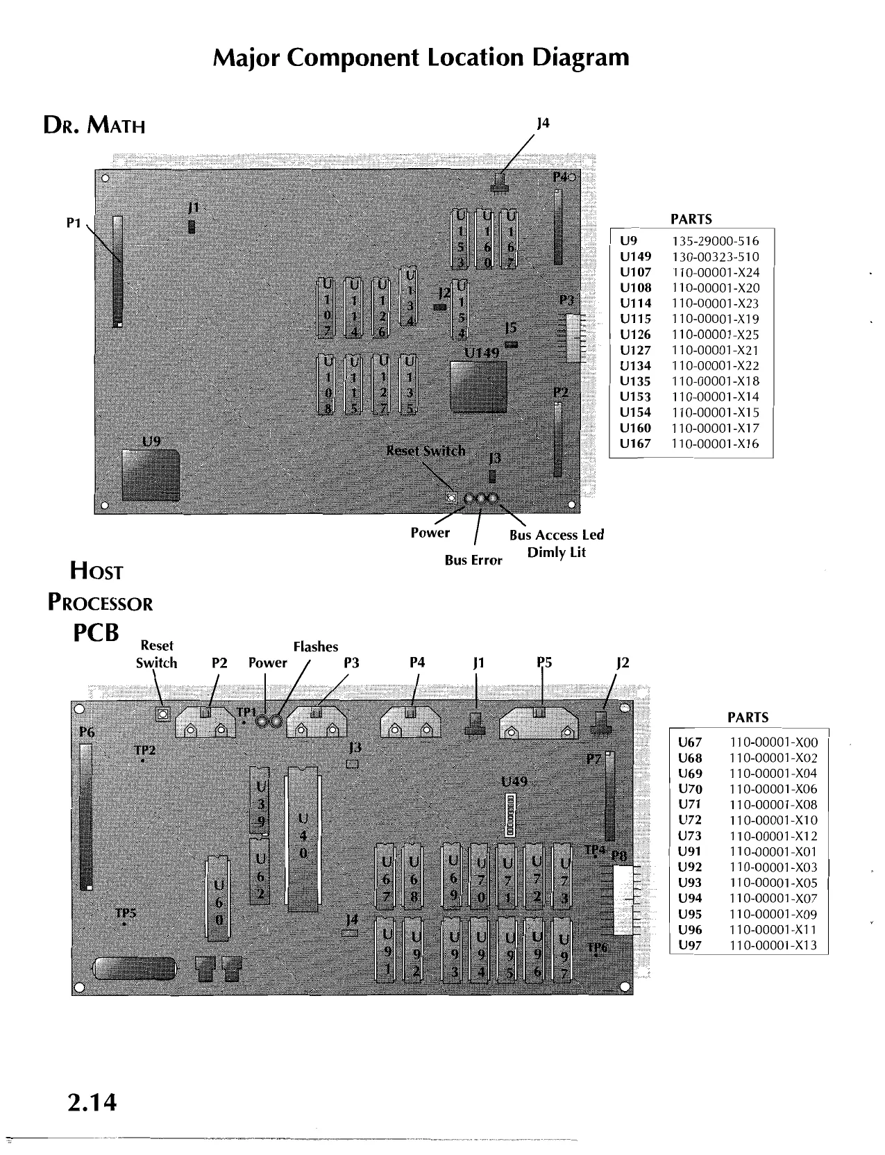
This page is a drawing, shown as the original scan.
Major Component Location Diagram
VIDEO Reset GRAPHIC PCB PARTS
u97 110-00002-X04 U101 110-00002-X01 U108 = 110-00002-X02 u114 110-00002-X03 U121 110-00002-X06 U124 —-110-00002-X05. U130 110-00002-X07 U133 110-00002-X08 u115 135-34010-440 U105 100-TB001-340 U107 100-PK001-320 U118 = 100-MW001-320 U119 100-MW001-320 U120 = 100-MW001-320 U127 100-MW001-320 U128 ~~ 100-MW001-320 U129 —_ 100-MW001-320
SOUND Pi “pv ov
PCB Power
Connector Test Reset
Right Speaker
Connector
Left Speaker
Connector
Power Amplifiers
NOTES
2.16
Maintenance
The following sections give detailed instructions in disassembling and reassembling the various parts of the game. The sections are arranged in the general order that they are encountered in the disassembly process. Because some steps in the complete disassembly sequence are not necessary to reach a particular part they are located under their own headings. Before beginning a repair, please read the entire procedure to familiarize yourself with the process.
Also, make sure that you have all of the required
tools at hand. When you reach the point in the disassembly procedure where you have removed the defective part, please skip ahead to the appropriate point and follow the reassembly instructions.
1. Joystick Switches
Open the coin door and release the spring latches that secure the control panel. It may be necessary to feed the wiring harness up through the joystick support tube to allow the switches to be removed from the grip.
Trigger Switch Disassembly:
1 Insert a flat bladed screwdriver behind the plastic trigger and carefully pry the switch out of the grip.
Assembly:
3 Using a pair of needle nosed pliers, grasp the wires near their tips and insert them into the appropriate holes in the switch. They should slide in and be secured by spring loaded tabs inside the switch.
3.1
3.2 Bend the wires out through the slots at the side of the switch and run them down the sides toward the back of the switch.
5 Holding the wires against the sides of the switch, insert the switch into the grip. The wires should fit snugly in channels beside the switch without getting pinched.
Lower thumb switch
Upper thumb switch Disassembly:
1 Loosen the set screw in the rear of the grip. 2 Grasping the small notches in the side of the red button, slide the switch out of the grip. 3 Remove the electrical tape and unsolder the 4 wires from the switch.
Assembly:
4 Solder the 4 wird athe switch and individually
wrap the connections in.electrical tape.
5 Slide the switch into the gtip and tighten the set
screw.
1 Remove the 4 screws that hold the switch mounting plate tothe grip and remove the plate. 2 Remove the electrical tape and unsolder the 4 wires from the switch.
3 Unscrew the silver ring nut from the switch and slide the switch out of the switch bezel and mounting plate.
4 Insert the switch into the switch bezel and tighten the silver ring nut against the back of the mounting plate. 5 Solder the 4 wires to the switch and individually wrap the connections in electrical tape.
6 Insert the mounting plate so the switch is on the left side of the grip and screw the plate in place.
2. Joystick
1 Open the coin door, release the spring latches that secure the control panel and tilt the control panel toward you to expose the joystick mechanism.
At this point the optical encoders can be removed and replaced without further disassembly of the joystick. This procedure is covered in section 4
joystick. This procedure is covered in section 4. 2 Remove the centering sensor mounting bracket from the position sensor assembly 3 Remove the 7 pin connector from the centering sensor.
Optional - See section 3 for disassembly of centering
sensor. 4 Remove the 5 pin connectors from the optical encoders.
5 Remove 4 screws that hold the optical encoder
assembly to the pivot assembly. 6 Slide the optical encoder assembly further on to the pivot assembly to expose the snap ring on the end of the joystick shaft.
7 Remove the snap ring and the bushing from the end
of the joystick shaft. 8 Slide the optical encoder assembly off the pivot assembly
Optional - See section 4 for disassembly of the optical encoder assembly
encoder assembly. 9 Remove the 4 carriage bolts that attach the pivot assembly to the joystick bezel and slide the joystick assembly up through the bezel, removing the joystick from the control panel. 10 Remove the lock nut from the lower end of the joystick shaft and slide the shaft out of the rubber pivot bushing, feeding the wiring bundle through the limit bumper.
3.3
3.4
Optional - See section 5 for disassembly of the pivot
assembly. 11 Using a drift and hammer, drive the 2 rol{ pins out of the support tube. 12 Slide the joystick shaft out of the tube.
Before proceeding further, follow the steps in section
1 to remove the switches from the grip. 13 Remove the 2 socket head screws from the left side of the joystick grip and slide the grip off the support tube. 14 Pull the wiring harness out of the support tube. 15 Disconnect the wires from all three switches and slide the wire harness out of the support tube, being careful not to tear the insulation. Assembly is the reverse of removal.
3. Centering sensor
Disassembly:
1 Remove the sensor circuit board from the 2 support legs. 2 Unsolder the 3 wires from from the center detect PCB. 3 Remove the support legs from the sensor mounting bracket.
Assembly:
4 Screw the support legs to the sensor mounting bracket. 5 Re-solder the 3 wires to the center detect PCB. Red wire to the hole marked “+5v ”, Black to “Gnd ” and white / yellow to “Out.” 6 Screw the sensor circuit board to the support legs with the black plastic optical sensor positioned at the middle of the sensor mounting bracket and facing up toward the bottom of the joystick shaft.
4. Optical encoders
Disassembly:
1 Remove the 2 screws that hold the encoder mounting plate to the encoder support bracket.
- Slide the encoder mounting plate out from behind the support bracket.
3 Loosen the set screw in the encoder gear and remove the gear from the shaft. 4 Remove the nut and lock washer from the encoder and slide the encoder out of the mounting plate. Although the hole in the mounting plate is not threaded, it may help to “unscrew” the encoder as you remove it.
If you are replacing an optical encoder, move to step
13 to install the new encoder and reassemble the optical encoder assembly. Repeat steps 1 through 4 for the other encoder. 5 Hold the 2 slider support bushings with a pair of pliers and remove their screws. 6 Pull the bushings out of the support bracket, releasing the slider. 7 Remove the rack from the slider. Repeat steps 5 though 7 for the other slider.
Repeat steps 5 though 7 for the other slider Assembly:
8 Mount the rack on the slider.
9 Insert the 2 slider screws through the holes in the support bracket and hold them there.
10 Place a flat washer over the screw closest to the encoder mount for that slider.
11 Place the slider over the screws with the rack next to the encoder mount and start the bushings into the screws.
12 Hold the bushings with pliers and tighten the screws, making sure that the bushings seat in the holes in the support bracket.
3.5
Repeat steps 8 though 12 for the other slider. Insert the encoder into the mounting plate. Place the lock washer and nut on the encoder shaft and tighten the nut. Slide the gear onto the encoder shaft as far as possible. The end of the gear with the set screw should be closest to the encoder housing. The rotational position of the gear is not important. Slide the mounting plate behind the support bracket and insert the 2 screws. Position the gear so that its teeth are fully engaged and run smoothly in the rack,
Tighten the screws and check the operation of the rack again. Make sure that the set screw does not bind in the rack.
Plug the 5 pin connector into the encoder. The connector with the green wire goes on the left/right encoder. The yellow wire goes to the up/down encoder. Repeat steps 13 though 18 for the other encoder.
5. Pivot
Disassembly:
1 Remove the pivot bushing from the pivot mounting bracket.
2 Remove the limit bumper plate from the pivot mounting bracket and pry the limit bumper form the plate.
Assembly:
3 Place the rubber bumper in the limit bumper plate with the narrow diameter at the bottom of the depression.
Attach the limit bumper plate to the pivot mounting
bracket. Mount the pivot bushing on the pivot mounting bracket. The slots in the end of the bushing face the
limit bumper and are parallel to the grommet mounting bracket.
6. Throttle
Disassembly:
1 Open the coin door, release the latches that secure the control panel and tilt the control panel toward you to expose the throttle mechanism.
2 Unplug the wiring harness from the throttle assembly. 3 Remove the potentiometer by loosening the set screw in the right end of the throttle pivot shaft. 4 Remove the bolt in the left end of the throttle pivot shaft and slide the throttle handle out.
5 Remove the 4 screws that hold the throttle pivot support brackets to the throttle trim plate. 6 Lift the throttle pivot assembly off the trim plate and remove the sliding throttle bezel and its retainer plate. 7 Remove the 3 silver bolts that connect the left and right throttle pivot support brackets 8 Separate the pivot support brackets, removing the throttle pivot and the limit bumpers. 9 Remove the 2 nylon washers from each end of the throttle pivot. Assembly is the reverse of disassembly.
3.7
7. Monitor
Disassembly:
1 Remove the screws holding the front and rear halves of the monitor shroud to each other.
2 Remove the screws holding the monitor shroud to the monitor support platform. 3 Carefully lift the rear half of the monitor shroud off the base and place it rightside up on a flat surface. 4 Remove the front half of the shroud in the same manner.
5 Remove the three screws from one of the two brackets at the side of the safety glass. The safety glass can be removed from either side of the unit by sliding it out of the front of the monitor bracket. Be careful not to let the bottom edge of the glass slip off its support. 6 Remove the ribbon cable from the monitor circuit board.
7 Unplug the wiring harness at the transformer at the right rear of the monitor assembly and at the fluorescent light fixture above the monitor. 8 Unfasten the cable ties that secure the light fixture wiring harness to the monitor assembly. 9 Remove the three screws that hold the light fixture to the top of the monitor assembly and remove the light fixture. 10 Remove the four nuts that hold the monitor assembly to the monitor support platform. 11 Stand in front of the game. Grasp the monitor assembly by the hand cutouts in the metal side panels. Tilt the monitor toward you and lift it off the support platform. Gently lower it to the floor, being careful not to bump the circuit board on the back of the picture tube.
Assembly:
12 Stand in front of the monitor. Grasp it by the hand cutouts in the metal side panels and lift it off the
floor. Gently place it on the support platform, being
careful not to bump the circuit board on the back of the picture tube. Make sure that the 4 bolts that secure the monitor assembly to the support platform extend through the holes in the metal brackets. 13 Tighten the nuts that secure the monitor assembly. 14 Place the fight fixture on top of the monitor assembly and secure it with the three sheet metal screws.
15 Plug in the wiring harness at the transformer and at the light fixture. 16 Secure the light fixture wires to the monitor assembly with cable ties. 17 Plug the ribbon cable into the monitor circuit board.
18 Place the plastic monitor bezel in the frame at the front of the monitor.
19 Carefully slide the safety class in from the side of the game, making sure that is does not slip off its support. Secure the safety glass bracket to the monitor frame with its 3 screws.
20 Carefully place the front half and then the back half of the monitor shroud on the monitor support platform and secure them loosely with their screws. 21 Insert and tighten the screws that hold the two shrouds to each other and then tighten the screws into the monitor platform.
8. Speakers
Disassembly:
1 Remove the 4 bolts that hold the metal speaker grill to the speaker cabinet. Remove the grill. 2 Remove the 4 screws that attach the front of the
speaker cabinet. Pull the speaker mounting board away from the speaker cabinet and unplug the speaker wire. 3 Remove the 4 nuts from the speaker and remove it from the mounting board. Repeat the same procedure for the other cabinet. Follow these steps in the reverse order to reassemble the speaker cabinet.
9. Electronics Tray
Removal:
The 3 main circuit boards are mounted vertically on the upper part of the tray. The power supply is suspended under the horizontal part of the tray. The sound board is mounted on the inside of the cabinet on the right side when viewed from the rear. The electronics tray can be removed from the game as a unit.
1 Turn off the power switch, unplug the power cord and open the rear door of the game.
2 Unplug the 2 wiring harnesses that connect the main circuit boards to the sound board.
- Begin to slide the tray out the back of the cabinet. Watch carefully for the other cables that need to be
unplugged. Some of the connectors at the top of the
circuit boards may be easier to disconnect after they are clear of the cabinet. There is a large wiring harness at the front of the boards that leads into the coin collection area. This needs to be unpluged before the tray is more than half way out.
4 Continue to slide the tray out and unplug comnectors as you go. Make sure all the cables are unpluged before you completely remove the tray from the cabinet.
5 Carefully pry the power connector from the edge of the circuit board stack. Leave the connector attached to the power supply cables.
6 Remove the RF shield from the circuit board stack.
7 Remove the 6 bolts that run through the posts at the corners of the circuit boards and lift the circuit board stack off the electronics tray. Replacement is the reverse of removal.
10. Changing the fluorescent lamp
Removal:
1 Remove the 6 screws that secure the attraction
panel and remove it from the monitor shroud. 2 Gently twist the lamp 1/4 turn in either direction and pull it down to remove it from the sockets.
- Slide the lamp to the left or right until the end can be passed out of the opening in the shroud.
3.11
NOTES
3.12
CHAPTER FOUR
This chapter contains illustrations and parts
lists of the assemblies used in this game. We
hope the illustrations will eliminate confusion when ordering parts and thus reduce any down-time you might experience
down-time you might experience.
Inside this chapter:
¢ (Illustrations of all major assemblies * Component Location Diagrams for all boards
© Parts list for all boards © List of all fuses ¢ List of harnesses ® List of decals
¢ Wiring Diagrams © Warranty information
¢ EPROM and PAL Location Chart
For further assistance please contact your distributor or
F-15 Strike Eagle™ was designed and manufactured in the United States.
4.1
Cabinet Assembly
5 Boge 29 3 £e ee oz Boa 3. gs Be 56 BE ga as 23° 3S SL ass 8835 333 8 go a ex s38 33 $8 Beas gs°D c 6 a oo Eg> & e 87 83 io oO
032-00001-005 Self-Test Panel fa Pere teste nk = eaten ata ie = Latch
520-00001-502 Volume Pot
625-00020-001 Self-Test Switch 625-00011-002 Start Switch 080-00003-002 Start Decal
625-00011-003 Decoy Switch 080-00003-001 Decoy Decal
032-00001-001 Control Panel
4.2
032-00001-001 032-00001-002 032-00001-005 032-00002-003 032-00002-004 080-00003-001 080-00003-002 320-00001-001 320-00001-002 520-00001-502 625-00020-001 625-0001 1-002 625-00011-003 695-00001-001
A21-00001 -001 031-00001-001 031-00002-001 031-00003-001 031-00005-001 031-01000-001 032-00003-001 032-00003-002 032-00003-003 032-00003-004 032-00003-006 321-00001-015 810-00001-001 032-00003-005
A10-10001-001 A10-10001-002 A10-10001-003 A18-00002-002 A18-00003-004 A18-00003-005 A18-00003-006 030-00005-001 032-00002-001 032-00002-002 032-00002-005 032-00003-003 032-00003-006 032-00004-004 625-00003-002 626-00001-001 690-00001-012 691-00001-001 696-00001-001 751-00001-001 770-00001-002 770-00100-001 Cabinet Assembly Parts List (4.2)
Control Panel Speaker Grill Self-Test Panel Diagnostic Contol Rear Metal Vent Rear Access Cover Decoy Decal Start Decal Attract Lights (Red) Attract Lights (Yellow) Volume Pot Self-Test Switch Start Switch Decoy Switch Speaker Front Vi
Coin Door Assembly Shroud, Front Shroud, Rear Plastic Bezel 25” Attract Plexiglass CRT Safety Glass Side Glass Clamp Top Glass Clamp Support, Left Support, Right Support, Top Fluorescent Light Monitor Support bottom
Deflection PCB Neck PCB Power Supply Fan Harness 100v AC Voltage Selection Harness 120v AC Voltage Selection Harness 240v AC Voltage Selection Harness Door Side Shroud Mounting Bracket Back Shroud Mounting Bracket Switch Mounting Bracket Left Support Top Suport Back Kickplate Power Switch Fluorescent Starter Fan Grill Transformer Power Cord Key Caster nti!
Rear View Parts List (4.5)
Front Exploded View
}-00025-710 Torex screw 10-32 x 3/4 031-00005-001 Attract Plexiglass
721-00012-001 Blind Nuts
031-00002-001 Shroud, Rear
Fluorescent Light ~ 031-00003-001 Plastic Bezel 25"
031-00001-001 032-00003-002 Top Glass Clamp,
031-01000-001 CRT Saftey Glass. Shroud, Front
810-00001-001 Support Top 032-00003-006 032-00003-003 Support, Left
Monitor
Support Right
032-00003-005 Support Bottom
Coin Door Assembly 032-00003-001 Side Glass Clamp
032-00004-002 Front Kickplate
4.4
Rear View
NOT SHOWN
A10-10001-004 A12-00002-001 Monitor Control PCB Fluorescent Fixture
A18-10000-001 626-00001-001 Remote Monitor Fluorescent Starter Control Harness 032-00003-006 Top Support
. A10-10001-003 Power Supply
032-00003-003 Left Support A10-10001-002 Neck PCB
032-00002-001 Side Shroud Mounting e Bracket (2 ) Monitor
625-00003-002 Power Switch 032-00002-005 Mounting Bracket A10-10001-001 Deflection PCB
032-00002-002 Back Shroud Bracket
770-00001-001 030-00005-001 Lock
770-00001-002 Key
696-00001-001 Transformer
A10-00005-001 Sound Board
Electronic Tray . Assembly
AC Voltage Selection Harness 100v A18-00003-004 120v A18-00003-005 240v A18-00003-006 032-00004-004 NOT SHOWN Back Kickplate 751-00001-001 Power Cord 770-00100-001 Caster (2)
Rear View
032-00002-003 Rear Metal Vent
032-00002-004 Rear Access Cover
A18-00002-002 Fan Harness 032-00004-003 691-00001-001 Front Kickplate, side Grill 690-00001-012 Fan
691-00001-001 Guard Grill 031-00004-001
Front Mat
031-00004-002 Rear. Mat 032-00004-001
Top Kickplate
4.6
Electronics Tray
A10-00001-001 Host Processor PCB
A10-00002-001 Dr. Math PCB A10-00003-001 Video Graphics PCB
010-0001 1-001 2 | 700-00001-003 Electronic Tray 4 ) Self-Retaining Spacer
596-00001-006 Power Supply Fuse, 6A SB
593-00001-001 Filter Assy.
596-00002-005 Power Entry Fuse, 5A SB 800-00001-001 Power Supply
PG Foy P7
% A18-00001-007 Host to VGB Ribbon Connector
610-00003-064 64 Pin Interboard Connector
uy
610-00003-040 40 Pin Interboard Connector
4.7
|2 +5VoUS
3 +5 VOLIS Be ce / 230V
115V
COMMON
Oe
Power Supply and Power Back Plane Board
Stud 9 +12VOLTS
V1 +15 VOLTS
12 - 15 VOLTS
Side View of Assembly
721-00520-410 (v3) +15 VOLT ADJ wy 5 VOLT ADJ
300-00001-002 Diode 5V Suppressor RSS (v4)
- 15 VOLT ADJ
a A10-00008-001 Power Back Plane Assembly
610-10101-010 Power Backplane Connector
4.8
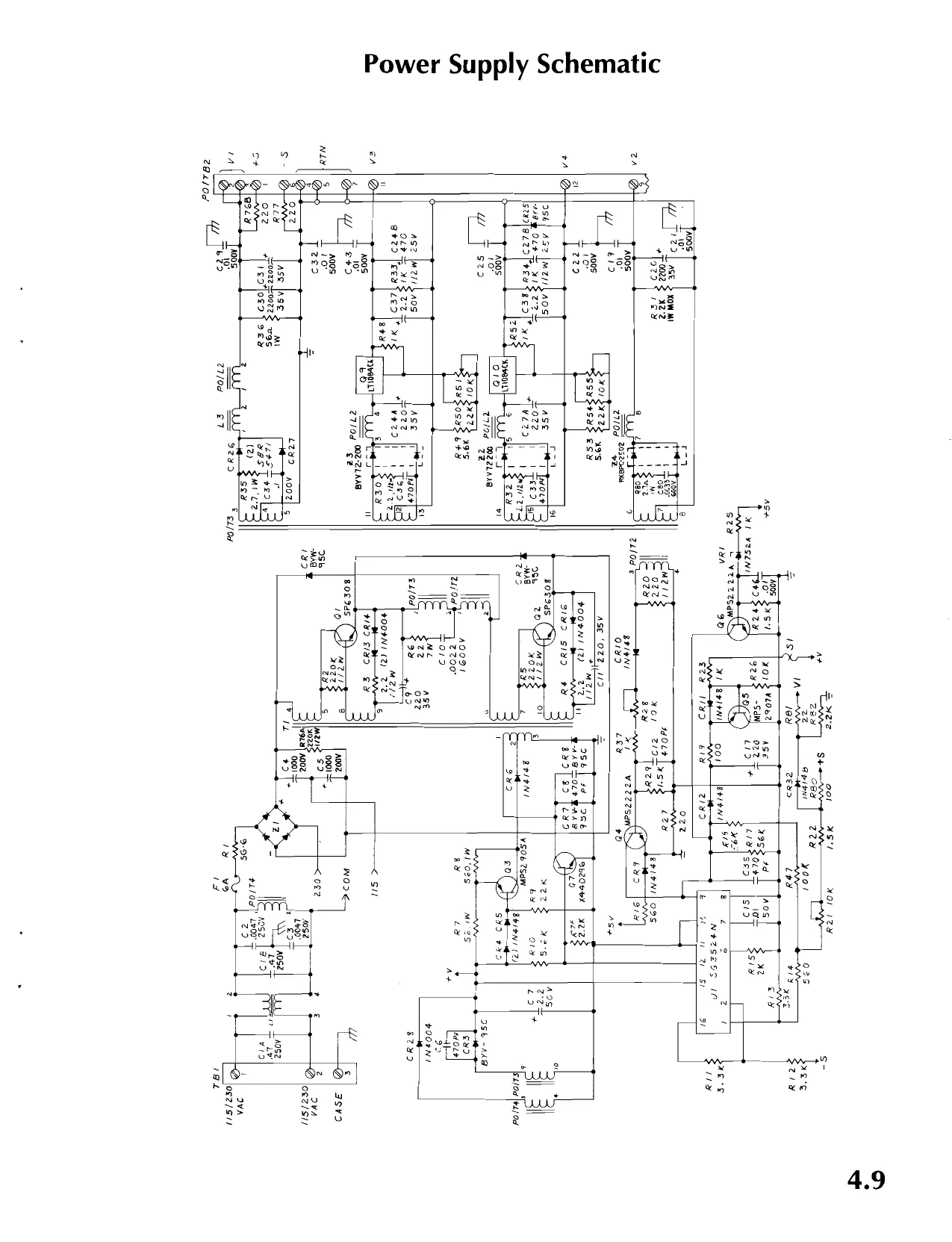
This page is a drawing, shown as the original scan.
Joystick Assembly P/N
“Carege Bot 1 #10 - 24x 5/8 \ 625-00010-001 Switch Trigger
020-00001-019 Jo: A20-00001-001
020-00001-020 Switch Plate 020-00001-021 “ Bezel, Switch
stick, Casting
sal cd 625-00011-001 ec Switch, Missile & Select
020-00001-016 Tube
020-00001-004 Boot Plate 720-00030-414 Roll Pin 1/8 x 7/8 (2)
020-00001-007 7 Bumper 020-00001-017 020-00001-022 Joystick Extension Shaft Washer
020-00001-003 Retainer
020-00001-001 020-00001-018 Top Assembly <a Roller Sleeve Bracket 020-00001-002 ow Grommet Mounting Bracket 720-00050-003 Retaining Ring H ee Ninto oa —_——+s 020-00001-008 U Bracket 020-00001-015 A18-00001-010 020-00001-005 “ Shoulder Rivet Wire Harness G ee 020-00001-012 720-00011-038 020-00001-006 Sli Washer, Snubbing e Locknut
020-00001-014 020-00001-013 Pinion Rack
020-00001-010 020- 0001-014 Adjusting Bracket me -00003-001 Pinion 721-00010-001 3/8 Nut 247-00001-001 9 . Encoder y Star Washer e— 247-00001-001 . /S Encoder 020-00001-013 Rack 020-00001-010 e Adjusting Bracket 020-00001-015 q Shoulder Rivet < A10-00025-001
020-00001-009 Opto Gaurd
4.10 Centering Sensor PCB Assembly
~~ 700-00010-003 Stand Off #4 - 5/8 inch
Joystick Assembly Parts List
A10-00025-001 020-00001-001 020-00001-002 020-00001-003 020-00001-004 020-00001-005 020-00001-006 020-00001-007 020-00001-008 020-00001-009 020-00001-010 020-00001-012 020-00001-013 020-00001-014 020-00001-015 020-00001-016 020-00001-017 020-00001-018 020-00601-019 020-00001-020 020-00001-021 020-00001-022 080-00001-008 247-00001-001 625-00010-001 625-0001 1-001 700-00010-003 720-00001-006 720-00002-006 720-00002-008 720-00002-010 720-00010-010 720-0001 1-038 720-00020-204 720-00020-406 720-00020-408 720-00022-204 720-00023-410 720-00024-414 720-00026-504 720-00028-610 720-00030-414 720-00050-003 721-00001-001 721-00001-002 Centering PCB Top Assembly Bracket Grommet Mounting Bracket Retainer Boot Plate Grommet Washer, Snubbing Bumper U-Bracket Opto Guard Adjusting Bracket Slide Rack Pinion Shoulder Rivet Tube Shaft, Extension Roller Sleeve Joystick, Casting Plate, Missile Switch Bezel, Switch Washer Decal, Top Plate Encoder Switch, trigger Switch, missile and select Stand off 5/8 “#4 screw Washer, flat #4 Lock washer #4 Lock washer #8 Lock washer #10 Hex nut #10-24 Locknut 3/8 Screw, pan head #4 x 1/4 Screw, pan head #6-32 x 3/8 Screw, pan head #8-32 x 3/8 Flat head socket cap screw #4 x 1/4 Screw, hex head #10-32 x 3/8 Screw, tamper proof #1/4-20 x 3/8 Set screw #4 x 1/2 Carriage Bolt #10-24 x 5/8 Roll pin 1/8 x 7/8 Retaining Ring Screw, round head #5-40 x 3/16 Lock washer #5
Centering PCB Parts List
Centering PCB Assembly Cap, Tantilum, 10 uF Cap, Ceramic, 0.1uF LED w/Res Voltage Comparitor Resistor, 4.7K Q Resistor, 22K Q Resistor, 22K Q Resistor, 10 Q Sensor RANMNANAB Bee ANN HEB onanhot
ARAM ARONAA
A10-00025-001 421-00032-106 402-00382-104 305-00003-002 280-00002-200 503-00002-472 503-00002-103 503-00002-223 503-00002-100 297-00100-001
4.11
020-00002-011 Throttle, Grip 720-00030-184 /~ NS Roll Pin
721-00024-510 Tamper Proof #10-32x1/2
080-00001-007 Decal 020-00002-005 Trim, Plate
020-00002-007 720-00023-714 Follower Hex Head Screw 1/4-20 x 3/4
020-00002-001 Top Plate 020-00002-003 Bracket, Left
020-00002-010 020-00002-006 Rubber Stop Shaft
: 721-00005-002 721-00023-014 & Nylon Thrust Bearing Hex Head Screw 1/4 - 20 X 2.0 020-00002-004
Side & Pot Bracket
520-00001-502 Potentiometer 020-00002-009 020-00002-008 Stop Insert Pivot Hub
720-00026-206 Hex Set Screw 6-32 x 1/4
720-00002-014 720-00010-014 Lockwasheer 1/4x20 Hex Nut 1/4x20
4.12
020-00002-001 020-00002-003 020-00002-004 020-00002-005 020-00002-006 020-00002-007 020-00002-008 020-00002-009 020-00002-010 020-00002-011 080-00001-007 520-00001-502 720-00002-014 720-00010-014 720-00023-714 720-00026-206 720-00030-184 721-00005-002 721-00023-014 721-00024-510
A12-00002-002 031-00001-002 032-00002-006 032-00002-007 080-00002-002 321-00001-015 626-00001-001 750-0001 0-001 750-00010-002 750-0001 0-003 Throttle Assembly A20-00002-001
Top Plate Bracket, Left Side and Pot Bracket Trim plate Shaft Follower Pivot hub Stop Insert Rubber Stop Throttle grip Decal, throttle Potentiometer Lock washer 1/4 Hex nut 1/4-20 Hex Head screw 1/4-20 x 3/4 Hex socket screw 6-32 x1/4 Roll pin 1/8 x 1 1/4 Thrust bearing, Nylon Hex Head screw 1/4-20 x 2.0 Tamper proof screw 10-32 x 1/2
Marquee Assembly
Fluorescent Fixture Sign Frame Sign Back Brace Marquee plexiglass Fluorescent Tube Starter 1/2" Lock Nuts With Nyion Ring 1/2" Pipe Fitting Washer 1/2" Nipple 1-1/2 in. long BONFAHWHOB Bay Hass
NARA oa aa
4.13
Marquee Assembly
032-00002-006 Sign Back
750-00010-003 1/2" Nipple 1-1/2 in. Long (2)
750-00010-001 1/2" Lock Nuts With Nylon Lock Ring (4) —SQS 750-00010-002 1/2" Pipe Fitting Washer (4) 031-00001-002 Sign Frame
il Directions imulators
080-0002-002 Marquee plexiglass
321-00001-015 Fluorescent Tube
A12-00002-002 Fluorescent Fixture
A18-00003-014 Top Marquee AC Harness
A18-00003-015 Not Shown Fluorescent Lamp"Y" Cable 032-00002-007 Brace
Connects to Attract Lamp
4.14 626-00001-001 Starter
jonnects to Top Marquee
Connects to Transformer
Host Processor PCB P/N A10-00001-001
4 . "ol o
4.15
C20 cat C22A,C22B
625-628 c29-Cat caz 033-C36 037,038 C39-C47 C48 c49-C52 053,054 C55A,C55B C56A,C568 57-C63 C64 Ces, C66 C67-C70 c71-C77 C78-C86 ce? ces c89-C95, C96 co7 C98.C107 C108 C109
02,03 D4 0s D6 p7-011 JW
wa 15,6 Pt P2 P3 Pa PS P6 P7 PB At Re i R4 RG R7-R10 RI
4.16 Host Processor PCB Parts List
LITHIUM BATTERY, 3 VOLT CAPACITOR, AXICER,0.1uF CAPACITOR,AX/TANT, 15uF CAPACITOR,AXICER0.1uF CAPACITOR,AX/TANT,3.3F CAPACITOR,AX/CER,0.1uF CAPACITOR,AX/CER,0.3F CAPACITOR,AXITANT, 15uF CAPACITOR,AX/CER,0.1uF CAPACITOR,AX/TANT, IHF CAPACITOR,AXICER,O.11F CAPACITOR,AX/TANT,3.90F CAPACITOR, AX/TANT, 15yF CAPACITOR DIPx4, 1) CAPACITOR,AXICER, 0.1 CAPACITOR,AX/TANT, 1 uF CAPACITOR,AXICER,0.33uF CAPACITOR,AXICER,0.1NF CAPACITOR,AX/TANT, 1H CAPACITOR AXICER, 0.1 pF CAPACITOR,AXICER,0.33nF CAPACITOR,AX/CER,O.1uF CAPACITOR,AXTANT, 1uF CAPACITOR,AX/CER,0.33nF CAPACITOR,AXICER0.1uF CAPACITOR,DIPx4,.1)1F CAPACITOR,DIPx4,.1)hF CAPACITOR,AXICER,0.1uF CAPACITOR AXICER,0.33,F CAPACITOR,AXICER,0.1pF CAPACITOR,AXICER,0.33uF CAPACITOR,AX/CER, 0.1)1F CAPACITOR,AX/CER0.93uF CAPACITOR,AXICER,01uF CAPACITOR,AX/TANT, 150 CAPACITOR,AX/CER,0. 1 CAPACITOR.AXICER0.33F CAPACITOR,AXICER,0.1uF CAPACITOR,AXITANT, 15 CAPACITOR,AX(CER,0.1pF CAPACITOR,AXITANT, 15uF CAPACITOR AX/CER,O.1NF DIODE LED WIRES, RED DIODE,ZENER DIODE,ZENER DIODE,ZENER,SV DIODE MOLEX 4-PIN,.100" 2-PIN JUMPER, 100° 3-PIN JUMPER,.100° FIBER OPTIC RCVR 2x3 HEADER, 100" 2x5 HEADER, 100" 2x10 HEADER,, 100" 2x8 HEADER, 100" 2x13 HEADER, 100" 2x32 HEADER, 100" 2x20 HEADER, 100" MOLEX 10-PIN,.156" RESISTOR,2%MF,820 RESISTOR 2%4MF, 1K RESISTOR, 2%ME,100K0 RESISTOR, JUMPER,0Q RESISTOR, 2%MF, 1802 RESISTOR 2%4MF 1KQ TEMP SENSOR, 5000 390-00001-001 402-00382-104 422-00052-156 402-00382-104 422-00062-335 402-00382-104 402-00382-334 422-00052-156 402-00382-104 422-00072-105 402-00382-104 422-00062-335, 422-00052-156 403-00003-104 402-00382-104 422-00072-105 402-00382-334 402-00382-104 422-00072-105 402-00382-104 402-00382-334 402-00382-104 422-00072-105 402-00382-334 402-00382-104 403-00003-104 403-00003-104 402-00382-104 402-00382-334 402-00382-104 402-00382-334 402-00382-104 402-00382-334 402-00382-104 422-00052-156 402-00382-104 402-00382-334 402-00382-104 422-00052-156 402-00382-104 422-00052-156 402-00382-104 300-00002-003 305-00003-002 301-02002-033 301-00002-047 300-00001-002 300-00002-003 610-00601-004 610-00002-002 610-00002-003 240-00004-001 610-00800-006 610-00800-010 610-00800-020 610-00800-016 610-00800-026 610-10100-064 610-00900-040 610-10600-010 503-00002-820 503-00002-102 503-00002-104 503-00001-000 503-00002-180 §03-00002-102 508-00001-501 22,23 U24 U25
ua? u28 U29,U30 U31-34 U35,U36 u37 U38 u3g u4o Uat
U53,U54 feos RESISTOR,2%MF 47022 RESISTOR, SIP,1KS PB SWITCH TEST PIN TEST PIN VOLT COMPARER, 14 DIP 9-BIT BUS DRIVER DRAM, i00NS- ‘SN74ALS245AN,OCTBIDBUFR ‘SN74ALS30AN,8INNAND RESISTOR,SIP,1KQ ‘SN74LS148N,8:3ENCODER RESISTOR, SIP,4702 RESISTOR,SIP,1KQ PAL ‘SN74ALS244AN,OCTBUFFR DUART DIP OSCILLATOR, 3.6864M 9-BIT BUS DRIVER ‘SN74ALS374N,OCTALDFLOPS RESISTOR, SIP,1KQ. SN74ALS244AN,OCTBUFFR LAMP DRIVER RESISTOR, SIP,470Q RESISTOR, SIP, 1KQ LAMP DRIVER RS232 DRIVER 9-BIT BUS DRIVER DRAM,100NS ‘SN74ALS245AN,OCTBIDBUFR: ‘SN74ALS175N,QUADDFLOPS ‘SN74ALS257N,2:1MUX SRAM,120NS MiCROPROCESR, 16MHz SN74AS1004AN,HEXINERTR ‘SN74AS74N,DUALDFLOPS: DIP OSCILLATOR, 32MHZ SN74AS244N,OCTBUFFR 9-BIT BUS DRIVER ‘SN74ALS138N,3:8DEMUX RESISTOR,SIP,1KQ. 8-POS DIP SW SN74ALS32N,QUAD2INOR ‘SN74AS244N,OCTBUFFR SN74ALS244AN,OCTBUFFR ‘SN74ALS2541N,OCTINVDRVR: ‘SN74ALS244AN,OCTBUFFR PAL PAL ‘SN74AS244N,OCTBUFFR PAL MFPERIPHERL ‘SN74ALS257N,2:1MUX ‘SRAM,120NS ‘SN74AS244N,OCTBUFFR: 9-BIT BUS DRIVER SN74AS244N,OCTBUFFR AD CONVERTER, EPROM,300NS EPROM,300NS EPROM,300NS EPROM,300NS EPROM,300NS EPROM,300NS EPROM,300NS. PAL PAL 503-00002-471 501-10008-102 625-00002-001 710-00001-001 710-00001-002 280-00003-200 235-00005-200 220-00001-210 200-00245-200 200-00030-200 501-00032-102 202-00148-200 501-00022-471 501-00031-102 120-00001-000 200-00244-200 240-00003-200 290-00002-003 235-00005-200 200-00374-200 501-00031-102 200-00244-200 279-00001-200 501-00022-471 501-00031-102 279-00001-200 235-00001-200 235-00005-200 220-00001-210 200-00245-200 200-00175-200 200-00257-200 221-00003-212 135-68000-216 201-01004-200 201-00074-200 290-00001-032 201-00244-200 235-00005-200 200-00138-200 501-00032-102 625-00001-208 200-00032-200 201-00244-200 200-00244-200 200-02541-200 200-00244-200 120-00001-004 120-00001-003 201-00244-200 120-00001-001 130-68901-204 200-00257-200 221-00003-212 201-00244-200 235-00005-200 201-00244-200 246-00001-200 110-00001-000 110-00001-002 110-00001-004 110-00001-006 110-00001-008 110-00001-010 110-00001-012 120-00001-002 120-00001-005
Host Processor PCB Parts List
U76 PAL 120-00001-007 94 EPROM.300NS. 110-00001-007 u77 PAL 120-60001-006 U9s EPROM,300NS_ 110-00001-009 u7s SN74LS393N,QUADCOUNTR 202-00393-200 U96 EPROM,300NS_ 110-00001-011 u79 RESISTOA,SIP,1KQ. 501-00032-102 U97 EPROM,300NS 110-00001-013 U8 ‘SN74AS244N,OCTBUFFR: 201-00244-200 UxX15, SOCKET 600-00001-320 U81 9-BIT BUS DRIVER 235-00005-200 UxX49 SOCKET 600-00001.964 U82 QUAD DECODER 246-00002-200 UX56,UX57 SOCKET 600-00001-320 U83 ‘SN74ALS244AN,OCTBUFFR 200-00244-200 UX59 SOCKET 600-00001-324 U84 RT CLOCK 291-01215-200 UX60 SOCKET 600-00001-648 U85 ‘SN74ALSO4BN,HEXINVERTR, 200-00064-200 UX67-UX73 SOCKET 600-00002-632 U86 ‘SN74ALS11AN,TRISINAND 200-0001 1-200 UX74-UX77 SOCKET 600-00001-320 U87 ‘SN74ALS04BN,HEXINVERTR: 200-00004-200 UXB8 SOCKET 600-00601-320 U88 PAL 120-00001-008. UX91-UX97 SOCKET 600-00002-632 U89 QUAD DECODER 246-00002-200 xt ORYSTAL,32KHz 290-00004-32K USO ‘SN74ALS244AN,OCTBUFFR 200-00244-200 ust EPROM,300NS 110-00001-001 ‘SPACER,.75" 700-00001-003 92 EPROM,300NS 110-00001-003 ‘SHUNT 715-00001-001 U93 EPROM,390NS 110-00001-005
135 180 225 Webbe butebebe ta tabebatetsrtate
a R
- 497 O- 4255—
be ® Narypeeeagernapeneapeaeepeneny FS R
4.18 SS coh mE . wo i
= Te Tog
qo":
walt “a al le
Dr. Math PCB Parts List
C14 C15-C17 C18 C19-C22
024-626 C27,C28 29,030 C31-C34 C35-C38 C39 40-048, C49,C50 Ct C52 C53 054-058. C59 C60-C84 85,086 C87-C92 C93-C96 C97-C101 C102 C103 C104,C105 C106-C111 112,013 C114-C122 C123 C124 C125 C126-C130 €131,C132 C133-C139 C140,C141 0142,0143. 0144-0146 C147-C152 C153 C154,C155 C156 C157,C158 C159 C160,C161 C162,C163 C164 C165-C172 C173 C174-C176 C177 C178-C184 C185 C186
C188 C189-C198 C199,C200
D1 d2 D3-D5 CAPACITOR,CERAMIC,0.1yF CAPACITOR, TANT, 15uF CAPACITOR, CERAMIC,0.1 uF CAPACITOR, CERAMIC,0.23F CAPACITOR, CERAMIC, 6.1 pF CAPACITOR, CERAMIC,0.33F CAPACITOR, CERAMIC, 0.1F CAPACITOR, CERAMIC,0.33,F CAPACITOR,CERAMIC,0.1yF CAPACITOR,CERAMIC,0.331F CAPACITOR, CERAMIC,0.1uF CAPACITOR, CERAMIC, 0.33, CAPACITOR, CERAMIC,0.1)F CAPACITOR, CERAMIC,0.33F CAPACITOR, CERAMIC,0.1HF CAPACITOR, CERAMIC, 0.33,F CAPACITOR,CERAMIC,0. uF CAPACITOR,CERAMIC,0.33 nF CAPACITOR, TANT 15, CAPACITOR, CERAMIC,0.1LF CAPACITOR, CERAMIC,0.330F CAPACITOR, CERAMIC, 0.1 uF CAPACITOR, TANT, 15uF CAPACITOR, CERAMIC, 0.1uF CAPACITOR,CERAMIC.0.33F CAPACITOR, CERAMIC 0.1 pF CAPACITOR, CERAMIC, 0.33,F CAPACITOR, CERAMIC,0.1,F CAPACITOR, TANT, 15 CAPACITOR CERAMIC,0.1,.F CAPACITOR, CERAMIC,0 33 CAPACITOR, CERAMIC 0.1 uF CAPACITOR, CERAMIC, 0.33yF CAPACITOR, CERAMIC, 0.1 ,.F CAPACITOR, CERAMIC 0.330F CAPACITOR, TANT, 15uF CAPACITOR, CERAMIC 0.33F CAPACITOR, CERAMIC. 0.1.F CAPACITOR, CERAMIC 0.33,F CAPACITOR, CERAMIC, 0.1yF CAPACITOR, CERAMIC, 0,33yF CAPACITOR, CERAMIC.0.1F CAPACITOR, CERAMIC,0.33F CAPACITOR, CERAMIC,0.1uF CAPACITOR, CERAMIC, 0.33.F CAPACITOR, CERAMIC,O.1 pF CAPACITOR, CERAMIC, 0.33nF CAPACITOR, CERAMIC,0.1)1F CAPACITOR,AX/TANT,3.30F CAPACITOR, CERAMIC,0.33F CAPACITOR, CERAMIC,0.1).F CAPACITOR, CERAMIC0.33F CAPACITOR, CERAMC,0.1F CAPACITOR, CERAMIC, 0.33uF CAPACITOR,AX/TANT, 1HF CAPACITOR, CERAMIC, 0.33 CAPACITOR, CERAMIC,0.1F CAPACITOR, CERAMIC,0.33.F CAPACITOR, CERAMIC,0.1)1F CAPACITOR, TANT, 15F CAPACITOR,AXTANT, 1p CAPACITOR, CERAMIC,0.1F CAPACITOR, TANT, 15uF CAPACITOR,AXICER, uF DIODE DIODEZENER,33V LED.RED 401-01000-104 420-00002-156. 491-01000-104 401-02000-334 401-01000-104 401-02000-334 401-01000-104 401-02000-334 401-01000-104. 401-02000-334 401-01000-104 401-02000-334 401-01000-104 401-02000-334 401-01000-104 401-02000-334 401-01000-104 401-02000-334 420-00002-156 401-01000-104 401-02000-334 401-01000-104 420-00002-156 401-01000-104 401-02000-334 401-01000-104 401-02000-334 401-01000-104 420-00002-156 401-01000-104 401-02000-334 401-01000-104 401-02000-334 401-01000-104 401-02000-334 420-00002-156. 401-02000-334 401-01000-104 401-02000-334 401-01000-104 401-02000-334 401-01000-104 401-02000-334 401-01000-104 401-02000-334. 401-01000-104 401-02000-334 401-01000-104 422-00062-335, 401-02000-334 401-01000-104 401-02000-334 401-01000-104 401-02000-334 422-00072-105 401-02000-334 401-01000-104 401-02000-334 401-01000-104 420-00002-156. 422-00072-105 401-01000-104 420-00002-156 402-00382-104 300-00002-03 301-00002-033 305-00603-002 Qt AL Re R3 R4,RS R6 R7,R8 RQ,R10 RIRI2 RI3,R14 RIS R16 RI7 RIB Rig R20 Ret Ree R23,R24, R25 Swi TP1-TP10 Ut U2,U3 U4,U5 U6-U8 ug U10 U11,U12 U13 U14-U16, U7 U8 UIs U20 u21 U22-U24 U25 u27 U28-U31
U33 U34,U35 U36 U37 U38 U39 U40-U42 U43,U44
46, Ud7,U48, U49-U51 U52,U53 US4 USS U56. us7 U58 DIODE,ZENER 2-PIN JUMPER,.100” 3-PIN JUMPER, 100" 4-PIN MOLEX, 100" 3-PIN JUMPER, 100" 2x82 HEADER,.100" 2x20 HEADER,.100" MOLEX 10-PIN,.156" VOLT COMPARER RESISTOR, 294MF,1KQ RESISTOR, 294MF,5600 RESISTOR, 2%MF, 100 RESISTOR,2°4MF,1KQ RESISTOR,2%MF,10KQ RESISTOR, 2%MF,5602 RESISTOR, 29%4MF, 1KQ. RESISTOR, 2%6MF,10 RESISTOR, 26MF,560 RESISTOR, 2%MF, 100 RESISTOR 2%MF,5600 RESISTOR, 2%4MF, 100 RESISTOR JUMPER 00 RESISTOR 276MF, 1K RESISTOR 2%6MF, 100KQ RESISTOR 2%MF,820 RESISTOR 276MF, 10K2 RESISTOR,29%MF,100 RESISTOR 24MF, 1KQ PB SWITCH TEST PIN 10-BIT BUFFER 9-BIT BUS DRIVER PULRESPAK,1KQ. SN74AS244DW,OCTBUFFERS MICROPROCESSOR, t6MHz 10-BIT BUFFER 9-BIT BUS DRIVER DRAM, 120NS SN74AS244DW,OCT BUFFERS OSCILLATOR 24MHz ‘SN74AS74N,DUAL DFLOPS ‘SN74AS1004AN,HEXINVDRIVRS. SN74ALS1O10N,TRISINNAND DRAM,120NS SN74AS244DWW OCTBUFFERS SN74AS1004AN, HEXINVDAIVAS. DRAM,120NS SN74AS244DW,OCTBUFFERS ‘ADM CADM DRAM,120NS SN74AS244DW,OCTBUFFERS DRAM,120NS SN74AS373DW,OCTD-LATCHES SN74AS373DW,OCTD-LATCHES SN74AS244DW,OCT BUFFERS ‘SN74AS245DW,OCT BI BUFFER SN74AS244DW OCT BUFFERS DRAM,120NS SN74AS373DW,OCTD-LATCHES ‘SN74AS244DW,OCT BUFFERS ‘SN744S245DW,OCT BI BUFFER SN74AS244DW,OCT BUFFERS MICROSEQUENCER SN74AS244DW,OCT BUFFERS DRAM, 120NS 9-BIT BUS REGISTER 300-00001-002 610-00002-002 610-00002-003 610-00601-004 616-00002-003 610-10100-064 610-10100-040 610-10600-010 280-00002-200 §03-00002-102 §03-00002-561 503-00002-100 503-00002-102 503-00002-103 503-00002-561 §03-00002-102 503-00002-100 503-00002-561 §03-00002-100 503-00002-56f 503-00002-100 503-00001-000 503-00002-102 503-90002-104 503-00002-820 503-00002-103 503-00002-190 503-00002-102 625-00092-001 710-00001-001 235-00006-200 235-00005-200 502-00001-102 201-00244-100 135-29000-516 235-00006-200 235-00005-200 220-00002-212 201-00244-100 290-00001-024 201-00074-200 201-01004-200 200-01010-200 220-00002-212 201-00244-100 201-01004-200 220-00002-212 201-00244-100 130-95C85-412 130-95C85-412 220-00002-212 201-00244-100 220-00002-212 201-00373-100 201-00373-100 201-00244-100 201-00245-100 201-00244-100 220-00002-212 201-00373-160 201-00244-100 201-00245-100 201-06244-100 130-00448-220 201-00244-100 220-00002-212 236-00004-100.
4.19
U70 U72-U74 U75,U76 ur7 U8 u7a U80,U81 U82 U83 U84 U85 Us6 U87 U88-U91 u92 U93 U95 U96 Us7 U98,U99 U100 u101 U102 U103 ‘U104 U105,U106 U107 U108 U109 U110 Uitt U112,U113 Uti4 U115 Ut16 U118 uid U120 u121 U122 U124 U125 U126 uie7
Ui29 U130 U131 U132 U133 U134 U135 U136 U137 U138 U139-U141 U142
4.20 Dr. Math PCB Parts List
‘SN74AS373DW,OCTD-LATCHES ‘SN74AS2440W,OCT BUFFERS PAL 74F269SC,DECADEU/DCNTR 9-BIT BUS REGISTER PAL ‘SN74AS244DW,OCT BUFFERS 10-BIT REGISTER ‘SN74AS244DW,OCT BUFFERS 74F269SC,DECADE U/D CNTR. PAL DRAM,120NS ‘SN74ALS2540N,OCTINVORVR ‘SN74AS258N,QUAD2:1MUX SN74AS175N,QUAD DFLOPS ‘74F269SC,DECADE U/D CNTR 9-BIT BUS REGISTER 9BIT BUS REGISTER DRAM,120NS. ‘SN74ALS2540N,OCTINVDRVR: ‘SN74AS258N,QUAD2:1MUX SN74AS244DW,OCT BUFFERS 9-BIT BUS REGISTER ‘SN74ALS138N,3:8 DEMUX DRAM,120NS ‘SN74ALS2540N,OCTINVDRVR SN74AS258N,QUAD2:iMUX PAL TA4F269SC,DECADEU/DCNTR PAL BIT BUS REGISTER EPROM,SONS EPROM,S0NS RAMADLDA,15NS ‘74F269SC,DECADE U/D CNTR DPSRAMA,15NS 9-BIT BUS REGISTER EPROM,S0NS. EPROM,S0NS. PAL PAL SN74AS1004AN,HEXINVDRIVRS PULRESPAK,1KQ. PAL PAL PULRESPAK,1KQ F74F189PC,4-BIT U/D CNTR EPROM,90NS EPROM,90NS ‘SN74LS393N,DUAL4-BITCNTR ‘SN74AS258N,QUAD2:1MUX SN7407N,HEXOCDRIVERS ‘SN74AS258N,QUAD2:1MUX SN74AS244DW,OCTBUFFERS: 74F269SC,DECADEU/DCNTR EPROM,90NS EPROM,90NS PAL 9-BIT BUS REGISTER PAL DPRAM45NS OSCILLATOR,32MHz 120-00001-020 201-00373-100 201-00244-100 120-00001-024 203-00269-100 235-00004-100 120-00001-010 201-00244-100 235-00003-200 201-00244-100 203-00269-100 120-00001-009 220-00002-212 200-02540-200 201-00258-200 201-00175-200 203-00269-100 235-00004-100 235-00004-100 220-00002-212 200-02540-200 201-00258-200 201-00244-100 235-00004-100 200-00138-200 220-00002-212 200-02540-200 201-00258-200 120-00001-019 203-00269-100 120-00001-015 235-00004-100 110-00001-024 110-00001-920 120-00001-018 203-00269-100 120-00001-014 235-00004-100 110-00001-023 110-00001-019 120-00001-123 120-00001-011 201-01004-200 502-00001-102 120-00001-021 120-00001-022 502-00001-102 203-00169-200 110-00001-025 110-00001-021 202-00393-200 201-00258-200 206-00007-200 201-00258-200 201-00244-100 203-00269-100 110-00001-022 110-00001-018 120-00001-017 235-00004-100 120-00001-016 222-00003-445 290-00001-032 u143 U144,U145 U146 u1a7 u1as ur49 U150,U151 Ut52 U153 U154 U185 Ut56 uis7 U159 ut60 ut6t Ut62 U163,U164 U165 Ut66 ut67 U168 Ut69 ut70,u171 ut72 vt73 Ui74,U175 Ut76 ut77 Ut78-U180 U181-U183 U184,U185 U186 UX9 UX55 UX59 UX67 Ux70 ux79 Uxt02 UXi04 UX107,108 UXx109 UX111 UX114,115 UX116,117 Ux118 UX121 UXx122 UX126,127 UX134,135, UX136 UX138 ux149 UX153,154 UX160 UX166 UX167 UX173 ‘SN74AS244DW,OCTBUFFERS. 9-BIT BUS REGISTER SN74AS74N,DUAL DFLOPS. ‘SN74AS08N,QUAD2INAND MAC IC, 10MHz_ ‘$N74AS244DW,OCT BUFFERS. DPRAM,45NS EPROM,150NS EPROM,150NS. 10-BIT BUFFER ‘SN74AS1004AN,HEXINVDRIVRS. 10-BIT BUFFER, UART EPROM, 150NS ‘SN74AS74N,DUAL DFLOPS. 9-BIT BUS REGISTER ‘SN74AS153N,4:1 DATA MUX 9-BIT BUS REGISTER MICROSEQUENCER EPROM, 150NS_ OSCILLATOR, 20MHz 9-BIT BUS REGISTER ‘SN74AS153N,4:1 DATA MUX 9-BIT BUS REGISTER MICROSEQUENCER ‘SN74AS153N,4:1 DATA MUX RS-232 DRIVER F74F169PC,4BITU/DCNTR ‘74F269SC, DECADE UD CNTR F74F169PC,4BITU/DCNTR ‘74F269SC,DECADE U/D CNTR 9-BIT BUS REGISTER 169-PIN PGA SOCKET 3x28-PIN SOCKET 3x24-PIN SOCKET 3x20-PIN SOCKET 3x24-PIN SOCKET 3x24-PIN SOCKET 3x24-PIN SOCKET 3x24-PIN SOCKET 6x28-PIN SOCKET 3x24-PIN SOCKET 3x24-PIN SOCKET 6x28-PIN SOCKET 3x20-PIN SOCKET 3x24-PIN SOCKET 3x24-PIN SOCKET 3x20-PIN SOCKET 6x28-PIN SOCKET 6x28-PIN SOCKET 3x24-PIN SOCKET ‘3x24-PIN SOCKET 169-PIN PGA SOCKET 6x32-PIN SOCKET 6x32-PIN SOCKET 3x28-PIN SOCKET 6x32-PIN SOCKET 3x28-PIN SOCKET
SHUNT SPACER,.750" 200-00004-200 201-00244-100 235-00004-100 201-00074-200 201-00008-200 130-00323-510 201-00244-100 222-00003-445 110-00001-014 110-00001-015 235-00006-200 201-01004-200 235-00006-200 240-00001-400 110-00001-017 201-00074-200 235-00004-100, 201-00153-200 236-00004-100 130-00448-220 110-00001-016 290-00001-020 235-00004-120 201-00153-200 235-00004-100 130-00448-220 201-00153-200 235-00001-200 203-00169-200 203-00269-100 203-00169-200 203-00269-100 235-00004-100 601-00002-169 600-00001-328 600-00001-324 600-00001-320 800-00001-324 600-00001-324 600-00001-324 600-00001-324 600-00001-628 600-00001-324 600-00001-324 €00-00001-628 600-00001-320 600-001-324 600-00001-324 600-00001-320 600-00001-628 600-00001-626 600-00001-324 600-00001-324 601-00002-169 600-00003-632 600-00003-632 600-00001-328 600-00003-632 600-00001-328
715-00001-001 700-00001-003
Video Graphics PCB P/N A10-00003-001
e) Q}
ae 8 _ = ~ - uf 3 3k ——
tts Cts: Gee i CI tppoe An if enc C28 exe Posse sgensooae UT lL csc ce ors
4.21
C18,C19 C20 C21 022-C25 C26
C28 C29 C30,C31
C34 C35 C36 C37-C40 041,042 043,044 C45 C46 47,048 C49 C50 C51 C52-C56 C57 C58 C59-C61 C62 C63 C65-C67 C68,C69 C70,C71 C72-C80 C94 C95-C99 Coo C101-C104 C105 C106 C107 C108 C109-C111 C112 C113-C115, C118,C117 118-6120 C121 C123 C125-C131 C132,C133 C134 C135 C136,C137 C138 139-0141 C142 C143 C144-C147
4.22 Video Graphics PCB Parts List
nape eaes Le
CAPACITOR,CERAMIC,0.1 pF CAPACITOR, TANT, 15 CAPACITOR,CERAMIC,0.1)1F CAPACITOR,CERAMIC,0.33pF CAPACITOR,CERAMIC,0.1 uF CAPACITOR, TANT, 15uF CAPACITOR,CERAMIC,0.33F CAPACITOR,CERAMIC,0. 1pF CAPACITOR,CERAMIC,0.33uF CAPACITOR,CERAMIC,0.1,F CAPACITOR,CERAMIC, 0.33, CAPACITOR, CERAMIC, 0.1 uF CAPACITOR,CERAMIC,0.33F CAPACITOR,CERAMIC, 0.1 1F CAPACITOR,CERAMIC,0.33,1F CAPACITOR,CERAMIC,0.1 uF CAPACITOR,CERAMIC,0.33uF CAPACITOR,CERAMIC,0.33 uF CAPACITOR, TANT, 10uF CAPACITOR, TANT, 33,F CAPACITOR,CERAMIC,0.01)F CAPACITOR,CERAMIC,0.33,F CAPACITOR,CERAMIC,0.1 uF CAPACITOR,CERAMIC,0.331F CAPACITOR,CERAMIC,0.11F CAPACITOR,CERAMIC,0.33F CAPACITOR, CERAMIC, 0.1 uF CAPACITCR,CERAMIC,0.33F CAPACITOR,CERAMIC,0.1 uF CAPACITOR,CERAMIC,0.33 nF CAPACITOR,CERAMIC,0.1 WF CAPACITOR,CERAMIC,0.33 uF CAPACITOR,CERAMIC,0.1,1F CAPACITOR,CERAMIC,0.33yF CAPACITOR, TANT, 15,F CAPACITOR,CERAMIC,0.1F CAPACITOR,CERAMIC,0.33.F CAPACITOR,CERAMIC,0.1 uF CAPACITOR,CERAMIC,0.1 F CAPACITOR, TANT, 11F CAPACITOR, TANT, 1F CAPACITOR,CERAMIC,0.1,1F CAPACITOR,CERAMIC,0.33uF CAPACITOR,CERAMIC,0.1,.F CAPACITOR,AX/TANT, 3.3 CAPACITOR,CERAMIC,0.11F CAPACITOR,CERAMIC,0.331F CAPACITOR,CERAMIC,0.11F CAPACITOR, TANT, 15F CAPACITOR,CERAMIC,0.33 uF CAPACITOR,CERAMIC,0.1,1F CAPACITOR,CERAMIC,0.33F CAPACITOR,CERAMIC,0.11F CAPACITOR,CERAMIC,0.33nF CAPACITOR,CERAMIC,0.1,4F CAPACITOR,CERAMIC,0.33F CAPACITOR,TANT, 15uF CAPACITOR,CERAMIC, 0.33 CAPACITOR,CERAMIC,0.1,1F CAPACITOR, TANT, 15uF CAPACITOR,CERAMIC.0.33 nF CAPACITOR,CERAMIC,0.1,1F CAPACITOR,CERAMIC,0.33F CAPACITOR,CERAMIC,0.1.1F CAPACITOR,CERAMIC,0.33,.F CAPACITOR,CERAMIC,0.1,1F CAPACITOR, CERAMIC, 0.33 HF 401-01000-104 420-00002-156 401-01000-104 401-02000-334 401-01000-104 420-00002-156 401-02000-334 401-01900-104 401-02000-334 401-02002-104 401-02000-334 401-01000-104 401-02000-334 401-02002-104 401-02000-334 401-01000-104 401-02000-334 401-02000-334 420-00162-106 420-00163-336 401-02002-103 401-02000-334 401-01000-104 401-02000-334 401-01000-104 401-02000-334 401-01000-104 401-02000-334 401-01000-104 401-02000-334 401-01000-104 401-02000-334 401-01000-104 401-02000-334 420-00002-156 401-01000-104 401-02000-334 401-01000-104 401-01000-104 420-00060-105 420-00060-105 401-01000-104 401-02000-334 401-01000-104 422-00062-335, 401-01000-104 401-02000-334 401-01000-104 420-00002-156 401-02000-334 401-01000-104 401-02000-334 401-01000-104 401-02000-334 401-01000-104 401-02000-334 420-00002-156 401-02000-334 401-01000-104 420-00002-156 401-02000-334 401-01000-104 401-02000-334 401-01000-104 401-02000-334 401-01000-104 401-02000-334 C148 149-0152 C153 C154 C155,C156 C187 158-6161 O1 D2 D3 D4D13 Did a J2
4d5, J6 w7 JB J9 J10 ule Pt P2 P3 Ri-R3 RA-RS R7 RB Ro R10 RY Ri2 R13 Ri4,R15 RI6 R17-Rt9 R20 R21 SWI ‘TP1,TP2 TP4-TP15 ul U2 U3 U4 US U6 U7 UB,U9 U10 ut U12U14 U1s U6 U17-U13 U20 U21 U22,U23 U24 U25
U27-U30 U31 U32 U33-U35 U36 CAPACITOR,CERAMIC,0.1pF CAPACITOR, CERAMIC, 0.33.F CAPACITOR, CERAMIC, 0.1).F CAPACITOR, TANT 15 CAPACITOR, CERAMIC,0.1pF CAPACITOR,TANT, 15pF CAPACITOR, CERAMIC,0.1F DIODE,ZENER, 1.2V DIODE,ZENER,3.3V DIODE LED, RED DIODE,ZENERS.0V 2X5 HEADER, 100° 3-PIN JUMPER, 100" MOLEX 4-PIN,, 100° 3-PiN JUMPER, 100" 2-PIN JUMPER,, 100" 3-PIN JUMPER,.100° 2-PIN JUNPER, 100° 3-PIN JUMPER,, 100° 2-PIN JUMPER, 100" FERRITE BD,75 2 2x20 CONNECTOR, 750" MOLEX 10-PIN, 156" 2x20 HEADER, 100° RESISTOR, 1%MF,10KQ RESISTOR, 196MF,75Q RESISTOR, 1%MF,15Q RESISTOR 1%MF,5490 RESISTOR, 1%MF,10KQ RESISTOR, 2%MF,1K&2. RESISTOR, 2%MF, 10K RESISTOR, 2%MF,820 RESISTOR, 2%MF,10KQ. RESISTOR, 2%MF, 102 RESISTOR,2%MF,10KQ RESISTCR,2%MF,10Q RESISTOR 274MF,10KQ RESISTOR, 2%MF 100 PB SWITCH TEST PIN TEST PIN SN74ALS244ADW,OCT BUFFERS SN74ALSO4BN, HEXINVERTERS SN74AS574N,OCT REGISTER \VRAM, 120NS VIDEO DAC, 30MHz SN74AS374N OCT REGISTER SN74ALS541N,OCT DRIVERS \VRAM,120NS SRAM,35NS| SN74AS157N,QUAD 2:1 MUX \VRAM,120NS ‘SRAM 35NS SN74AS574N,OCT REGISTER VRAM,120NS ‘SRAM,35NS SN74ALS541N,OCT DRIVERS \VRAM,120NS \VRAM,120NS SRAM,35NS SN74AS157N,QUAD 2:1 MUX \VRAM,120NS SN74AS374N,OCT REGISTER SN74AS157N,QUAD 2:1 MUX \VRAM,120NS SN74AS32N,HEX 2-IN'OR’ avo
401-01000-104 401-02000-334 401-01000-104 420-00002-156 401-01000-104 420-00002-156 401-01000-104 301-00001-012 301-00002-033 300-00002-003 305-00003-002 300-00001-002 610-00800-010 610-00002-003 610-00601-004 610-00002-003 610-00002-002 610-00002-003 610-00002-002 610-00002-003 610-00002-002 595-00001-100 610-10103-040 810-10600-010 610-00900-040 503-20001-103 503-00001-750 503-00001-150 503-00001-551 503-00001-103 $03-00002-102 503-00002-103 503-00002-820 503-00002-103 503-00002-100 503-00002-103 503-00002-100 503-00002-103 503-00002-100 625-00002-001 710-00001-001 710-00001-001 200-00244-100 200-00004-200 201-00574-200 222-00006-612 245-00001-230 201-00374-200 200-00541-200 222-00006-612 221-00002-235 201-00157-200 222-00006-612 221-00002-235 201-00574-200 222-00006-612 221-00002-235 200-00541-200 222-00006-612 222-00006-612 221-00002-235 201-00157-200 222-00006-612 201-00374-200 201-00157-200 222-00006-612 201-00032-200
u47 u4g U50 US1 U53 U54 USS U56 US7,U58 U59 U60 U61 U62 U63 U64 U65 U66,U67 U68 U69 u70 U7 u72 U73,U74 U5 U76 u77 DRAM,120NS PULRESPAK, 10K ‘SN74ALS2541N,OCT DRIVER PAL \VRAM,120NS ‘SN74ALSO4BN,HEXINVERTERS DRAM, 120NS ‘SN74ALS273N,OCT REGISTERS PAL ‘SN74AS253DW, DUAL 4:1 MUX ‘SN74AS244DW, OCT BUFFERS SN74ALSO4BN HEXINVERTERS DRAM,120NS ‘SN74ALS273N,OCT REGISTERS SN74ALS74N,DUAL DFLOPS DRAM, 120NS ‘SN74ALS273N,OCT REGISTERS PAL SN74AS253DW, DUAL 4:1 MUX SN74AS2440W,OCT BUFFERS RS-232 DRIVER, PULRESPAK,10KQ. ‘SN74ALS244ADW,OCT BUFFERS. 10-BITL ATCHES SN74ALS273N,OCT REGISTERS PAL SN74AS253DW, DUAL 4:1 MUX SN74AS244DW, OCT BUFFERS UART SN74ALSO8N,HEX2-IN'AND' 9-BIT XCVR PAL SN74AS253DW,DUAL 4:1 MUX SN74AS244DW,OCT BUFFERS SN74ALS373N,OCT LATCHES PAL 9-BIT LATCH PAL SN74ASO4N,HEX INVERTER ‘SN74AS253DW,DUAL 4:1 MUX ‘SN74AS244DW,OCT BUFFERS SN74LS14NHEX STINVERT ‘SN74ALS373N,OCT LATCHES PAL PAL SN74AS1034AN,HEX DRIVER VOLT COMP SN74ALS373N,OCT LATCHES OSCILLATOR,50MHz PAL DPSRAM,35NS EPROM, 150NS ‘SN74ALS245ADW,OCTXCVR ‘SN74AS1004AN,HEX INVDRVRS 220-00002-212 502-00001-103 200-02541-200 120-00002-007 222-00006-612 200-00004-200 220-00002-212 200-00273-200 120-00002-001 201-00253-100 201-00244-100 200-00004-200 220-00002-212 200-00273-200 200-00074-200 220-00002-212 200-00273-200 120-00002-011 201-00253-100 201-00244-100 235-00001-200 502-00001-103. 200-00244-100 235-00008-100 200-00273-200 120-00002-010 201-00253-100 201-00244-100 240-00002-200 200-00008-200 235-00005-200 120-00002-004 201-00253-100 201-00244-100 200-00373-200 120-00002-008 235-00004-100 120-00002-005 201-00004-200 201-00253-100 201-00244-100 202-00014-200 200-00373-200 120-00002-009 120-00002-003 201-01034-200 280-00002-200 200-00373-200 290-00001-050 120-00002-002 222-00002-435 110-00002-004 200-00245-100 201-01004-200 U101 U102,U103 U104 U105, U106 U107 U108 U109,U119 uttt uti2 U113 uid U115 U116 Ut17 U118-U120 ut21 U122 U123 U124 U125 U126 U127-U129 U130 U131 U132 U133 U135, U136-U139 U140 U141-U144 U145 uc72 uc77 UC86,UC87 UC93 UX40 UX45. UX65, UX79 UX97 UX101 UX108 UX114 UX115 UX121 UX124 UX130 UX133 UX140 EPROM,150NS ‘SN74ALS245ADW,OCTXCVR OSCILLATOR,40MHz DRAW2 ASIC,40MHz DPSRAM,35NS_ DRAW1 ASIC,20MHz BEPROM,150NS ‘SN74ALS245ADW,OCTXCVR SN74AS1004AN,HEX INVDRVRS PULRESPAK,10KQ. DPSRAM,35NS_ EPROM,150NS 68PLCCGSP,40MHz SN74AS74N,DUAL DFLOPS SN74AS1004AN,HEX INVDRVRS CLIPPER ASIC,20MHz EPROM,300NS PULRESPAK, 10KQ. ‘SN74LS393N, DUAL 4-BIT CTR EPROM,300NS ‘SN74ALS157N,QUAD2:1MUX SN74AS1004AN,HEX INVDRVRS CLIPPER ASIC,20MHz EPROM,300NS OSCILLATOR,20MHz ‘SN74LS14N,HEX STINVERT EPROM,300NS ‘SN74LS14N,HEX STINVERT FIFO,50NS. PAL ‘SN74AS244DW,OCT BUFFERS: PULRESPAK,10KQ. 24-PIN SOCKET,.300" 24-PIN SOCKET,.300” 24-PIN SOCKET,.300" 24-PIN SOCKET, 300" 20-PIN SOCKET, .300" 20-PIN SOCKET,.00" 20-PIN SOCKET,.300" 20-PIN SOCKET,.300" 32-PIN SOCKET,.600" 32-PIN SOCKET,.600" 32-PIN SOCKET, .600" 32-PIN SOCKET, 600" 68 PLCC SOCKET 32-PIN SOCKET,.600" 32-PIN SOCKET,.600" 32-PIN SOCKET,.600" 32-PIN SOCKET,.600" 20-PIN SOCKET,.300"
‘SPACER,.750" SHUNT 110-00002-001 200-00245-100 290-00001-040 100-TB001-340 222-00002-435 100-PK001-320 110-00002-002 200-00245-100 201-01004-200 502-00001-103 222-00002-435 110-00002-003 135-34010-440 201-00074-200 201-01004-200 100-MW001-320 110-00002-006 502-00001-103 202-00393-200 110-00002-005 200-00157-200 201-01004-200 100-MW001-320 116-00002-007 290-00001-020 202-00014-200 110-00002-008 202-00014-200 222-00004-450 120-00002-006 201-00244-100 502-00001-103 600-00001-324 600-00001-324 600-00001-324 600-00001-324 600-00001-320 600-00001-320 600-00001-320 600-00001-320 600-00002-632 600-00002-632 600-00062-632 600-00002-632 602-00001-068 609-00002-632 600-00002-632 600-00002-632 600-00002-632 600-00001-320
700-00001-031 715-00001-001
4.23
This page reads as a drawing: its text was drawn rather than typeset, and comes out in fragments. See the original scan.
C6-C9 C10,C11 Ci2 C13 C14 C15 C16 Ci7 C18-C20 Cai 22,023 C24,C25 C26 C27-C38 C39 C40 641,042 643,044. C45 C46 aT C48 cag C50 C51 C52-C54 C55 C56 C57 C58 59,080 C61 C62 C63 64,065 C66 C67 C68 C69 C70 cn 072,073 C74 Cm CAPACITOR, AX/CER,22pF CAPACITOR,AX/TANT, 1 0uF CAPACITOR,AX/CER, .22uF CAPACITOR,AX/TANT, 1 pF CAPACITOR,AX/CER,220pF CAPACITOR,AX/CER,.1F CAPACITOR,AX/CER,.022uF CAPACITOR,AX/CER,220pF CAPACITOR,AX/CER,.022uF CAPACITOR,AX/CER,.01NF CAPACITOR,AX/TANT, 1 LF CAPACITOR,AX/TANT, 1 0uF CAPACITOR,AX/CER,.10F CAPACITOR,AX/CER,.3ouF CAPACITOR,AX/CER,.1 uF CAPACITOR,AX/CER,.33F CAPACITOR,AX/CER, 1 F CAPACITOR,AX/CER,22pF CAPACITOR, AX/TANT, 1 WF CAPACITOR, AX/CER,2200pF CAPACITOR,AX/CER,.1 UF CAPACITOR,RAD/CER, uF CAPACITORAX/TANT,1 UF CAPACITOR,AXICER,.01pF CAPACITORAXCER,.1 UF CAPACITOR,AX/CER,.O1MF CAPACITOR, AX/CER,.1 uF CAPACITOR, AX/CER,.01uF CAPACITOR,AX/CER, 1 uF CAPACITOR,AX/CER,.01F CAPACITOR,POLYFILM,6800pF CAPACITOR,AX/CER,.01F CAPACITOR,POLYFILM,1300pF CAPACITOR,RAD/TANT, 47 CAPACITOR,POLYFILM,1300pF CAPACITOR,AX/CER,.1)F CAPACITOR,POLYFILM,6800pF CAPACITOR,AX/CER,.01,F CAPACITOR,AX/CERA, 1 00pF CAPACITOR,AX/CER,.01yF CAPACITOR,AX/CER,.001 WF CAPACITOR,RAD/CER, 1uF CAPACITORAX/CER,.001 HF CAPACITOR,AX/TANT, 10uF CAPACITOR,AXICER,.22uF CAPACITOR,AX/CER,.001UF CAPACITOR,AX/TANT,10F CAPACITOR,RADICER, 1UF CAPACITOR, AX/CERA, 1 00pF CAPACITOR, AX/CER, .01),F CAPACITOR, AXICER, 1 F CAPACITOR,AXICER, 1 uF CAPACITOR,RAD/CER,1yF CAPACITOR,RAD/TANT,1000uF CAPACITOR, AX/CER,.33HF CAPACITOR,AX/CER,.11F CAPACITOR,AX/CER,.0011F CAPACITOR, AX/CER,.1.F CAPACITOR,AX/CER,.22uF CAPACITOR,AX/TANT, 10uF CAPACITOR,AX/CER..1 UF CAPACITOR,AX/CER,.01 WF CAPACITOR,AX/CER, .1F LED,RED DIODE,RECTIFIER LED,RED DIODE,SIGNAL Sound PCB Parts List
402-00195-220 422-60072-106 402-00285-224 422-00072-105 402-00195-221 402-00285-104 402-00285-223 402-00195-221 402-00285-223 402-00285-103 422-00072-105. 422-00072-106 402-00382-104 402-00382-334 402-00382-104 402-00382-334 402-00382-104 402-00195-220 422-00072-106 402-00295-222 402-00382-104 400-00281-105 422-00072-105 402-06285-103 402-00285-104 402-00285-103 402-00285-104 402-00285-103 402-00285-104 402-00285-103 430-00002-682 402-00285-103 430-00001-132 421-00020-476 430-00001-132 402-00285-104 430-00002-682 402-00285-103 402-00195-101 402-00285-103. 402-00295-102 400-00281-105 402-00295-162 422-00072-106 402-00285-224 402-00295-102 422-00072-106 400-00281-105 402-00195-101 402-00285-103. 402-00382-104 402-00285-104 400-00281-105 410-00002-108 402-00382-334 402-00382-104 402-00295-102 402-00382-104 402-00285-224 422-00072-106 402-00285-104 402-00285-103 402-00382-104 305-00003-002 302-00001-007 305-00003-002 300-00002-003 R10
R12 R13 Ri4 RIS RI6 RI7-R19. R20 Rat R22 R23 R24 R25 R26 R27 R28 R29 R30 R31
R33,R34 R35 R36 R37 R38 R39 R40 Rat R42,R43 R44 R45 RAG R47,R48 R49 R50 R51 R52 R53. R54,R55
R57 R58 R59 R60 R61,R62 DIODE,ZENER,SV DIODE,ZENER,15V DIODE,ZENER,5V DIODE,ZENER,15V DIODE,SCHOTTKY DIODE,RECTIFIER DIODE,SCHOTTKY 4-PIN MOLEX,.100° 2-PIN MOLEX,.100" 4-PIN MOLEX,.100" INDUCTOR,250uH 4-PIN POWER CON,.200" TRANSISTOR,PNP AUDIO POWER AMP RESISTOR,1%MF,1.06KQ RESISTOR,1%MF,8.25KQ. RESISTOR, 1%MF,100KQ RESISTOR,1%MF,301 2 RESISTOR, 1%MF,27402 RESISTOR, 1%MF,100KQ. RESISTOR, 1%MF, 1.00KQ2 RESISTOR, 1%MF,100KQ. RESISTOR, 1%MF,1.30KQ. RESISTOR, 1%MF,12.1KQ_ RESISTOR, 1%MF,1.30KQ. RESISTOR, 1%MF,6.19KQ. RESISTOR,1%MF,5.11KQ. RESISTOR, 1%MF,1.00KQ. RESISTOR,1%MF,536Q2 RESISTOR, 1%MF, 16.5KQ. RESISTOR,1%MF,10.0KQ. RESISTOR,1%MF,1.00KQ. RESISTOR, 1%MF,5.11KQ. RESISTOR, 1%MF,2.15KQ. RESISTOR,1%MF,5.11KQ. RESISTOR,1%MF,10.0KQ RESISTOR, 1%MF 5362. RESISTOR, 1%MF,5.11KQ. RESISTOR, 1°%MF, 16.5KQ. RESISTOR, 1%MF,2.15KQ. RESISTOR, 1%MF,5.11KQ. RESISTOR, 1%MF,10.0KQ RESISTOR, 1%MF,5362. RESISTOR, 1%MF,8250. RESISTOR,5%MF,1.56MQ. RESISTOR, 1%MF,43.2KQ_ RESISTOR, 1%MF,10.0KQ. RESISTOR, 1%MF,825Q RESISTOR,5%MF,1.5MQ RESISTOR, 1%MF,43.2KQ, RESISTOR,1%MF,33.2KQ. RESISTOR,1%MF,274KQ. RESISTOR,1%MF,47.5KQ. RESISTOR, 1%MF, 16.5KQ RESISTOR,1%MF,33.2KQ. RESISTOR,1%MF,16.5KQ. RESISTOR, 1%MF,5.11KQ. RESISTOR,1%MF,33.2KQ. RESISTOR, 1%MF,1.00KQ. RESISTOR, 1%MF,10.0KQ. RESISTOR,5%MF, 12 RESISTOR, 1%MF.5.11KQ. RESISTOR,1%MF ,1.00KQ. RESISTOR, 1%MF,10.0KQ. RESISTOR, 1%MF,5.11KQ. RESISTOR,.2%MF 6802 RESISTOR, 1%MF,5.11KQ. 300-00001-002 300-001-005 300-00001-002 300-00001-005 302-00002-001 302-00001-001 302-00002-001 610-00102-004 610-00102-002 610-00102-004 590-00001-001 610-00300-004 310-00001-001 282-02030-600 503-00001-102 503-00001-822 503-00001-104 503-00001-301 503-00001-001 503-00001-104 503-00001-102 503-00001-104 503-00501-132 503-00001-123 503-00001-132 563-00001-612 503-00001-512 503-00001-102 503-00001-541 503-00001-163 503-00001-103 503-00001-102 503-00001-512 503-00001-212 503-00001-512 503-00001-103 503-00001-541 503-00001-512 503-00001-163 503-00001-212 503-00001-512 503-00001-103 503-00001-541 503-00001-831 503-00005-155 503-06001-433 503-00001-103 503-00001-831 503-00005-155 503-00001-433 503-00001-333 503-00001-274 503-00001-473. 503-00001-163 503-00001-333 503-00001-163 503-00001-512 503-00001-333 503-00001-102 503-00001-103 503-00005-010 503-00001-512 503-00001-102 503-00001-103 503-00001-512 503-00002-681 503-00001-512
4.25
Sound PCB Parts List
SW1,SW2 TP1,TP2 ul v2 V3 us Us U6 u7 us ug Uto
4.26 RESISTOR, 1%MF,33.2KQ. RESISTOR, 2%MF,6802. RESISTOR,1%MF,5.11KQ. RESISTOR, 1%MF 33.2KQ. RESISTOR, 1%MF,33.2KQ. RESISTOR, 1%MF,1.00KQ. RESISTOR, 1%MF,10.0KQ RESISTOR, 5%MF, 10. RESISTOR,1%MF,5.11KQ. RESISTOR, 1%MF,33.2KQ. RESISTOR, 1%6MF,165K& RESISTOR,2%MF,1MQ_ RESISTOR, 1%MF,33.2KQ. RESISTOR, 1%MF, 165KS2 PB SWITCH TEST PIN OCTAL D-FLOPS EPROM,300NS- MICROPROCESSSOR, 1 2MHz DUAL ONE-SHOT QUAD 2-IN NAND. HEX INVERTORS ‘SRAM,45NS RS-232 DRIVER NEG. 5V REG SPEECH GEN 503-00001-333 503-00002-681 503-00001-512 503-00001-333 503-00001-333 503-00001-102 §03-00001-103 503-00005-010 503-00001-512 503-00001-333 503-00001-174 503-00002-105 503-00001-333 503-00001-174 §25-00002-001 719-00001-001 200-00373-200 110-00004-001 135-80C31-212 202-00123-200 202-00000-200 200-00004-200 221-00004-245, 236-00001-200 281-07905-001 282-07759-200 PAL MUSIC SYNTH STEREO DAC D/ACONVERTER DUALOP AMP OCTAL D-FLOPS: EPROM,300NS. DUAL OP AMP NOISE GEN DUAL OP AMP MUSIC VOICE 8 CHANS/HOLD DUALOP AMP DUAL DIG POTS,50KQ DUAL OP AMP. 28-PIN SOCKET,.600" 40-PIN SOCKET,.600" 20-PIN SOCKET, 300" 32-PIN SOCKET,.600" OSCILLATOR, 11.06MHz CER RESONATOR,640KHz. ‘SNDXTAL,3.58MHz
CLIP,HEATSINK HEATSINK 120-00003-001 282-02181-200 282-03012-200 245-00003-200 282-00072-200 200-00373-200 119-00003-001 282-00072-200 282-05437-200 282-00072-200 282-02047-200 282-02300-200 282-00072-200 282-01267-200 282-00072-200 600-00001-628 600-00003-640. 600-00001-320 600-00003-632 290-00003-011 290-00005-640 290-00003-003
790-00001-002 790-00001-001
Coin Co Coin Door
@ Coinco.
2822-208 GAME DOOR
OVERALL DIMENSIONS Height . . . +++. 20-7/8-Inches . 7-7/8-Inches .. 4-1/2-Inches 9-3/4-Inches
SHIPPING WEIGHT Without Cashbox . With Cashbox
FRONT VIEW
EXPLODED VIEW (See reverse side for Parts List)
4.27
Coin Co Coin Door Parts List
2822 SERIES GAME DOOR PARTS LIST
Index Part
No. Description No. No. Description
| 905640 | Coin Door Frame | 23° | 110-4-6 | Screw |
| 404696-2 | Coin Door | 24 | =904722 | Wire Key Holder |
| 404696 | Service Door | 25 | 400-4 | Nut |
| 404697-1 | Coin Door inner Panel | 26 | 404645 | Coin Inlet Chute Assembly |
| 404767 | 7/8-Inch Flat Key Lock | 27 | 904583-1 | Coin Return Lever |
| 905651-2 | CAM, Lock | 28 | 108B5-4 | Screw |
| 905484 | Coin Return Door | 29 | 904936 | A.PF Bar Keeper |
904590-2 Coin Return Bezel 905425-4 Coin Inlet Bezel {1.000 Coin Diameter)
404604 Button Assembly 905423-1 Button Cover (Not Illustrated) 905424-3 Button (only) (Not Illustrated)
| 904703 | 25¢ Decal (Not Illustrated) | 904598-1 | Coin Return Box |
904778 Token Decal (Not Illustrated) 904935, APF Bar
| 903494 | Spring | 404601 | ‘Switch and C.R.E.M. Bracket |
| 909913 | Screw | 904701 | Coin Chute |
906030 identification Label 904845 Coin Switch
904822 Slam Switch Insulation 904710-1 25¢ Switch Wire
| 905658-2 | Mounting Clip, Slide | 900651 | Switch Wire Retainer |
| 328-10-8 | Screw | 404353 | 25¢ Coin Switch Assembly |
| 400-8 | Nut | 100-4-12 | Screw |
904762-1 Switch Cover 5301-13 25¢ NORYL Acceptor
| 904716-1 | Lamp (12voli) | 406953 | Cashbox and Enclosure |
Assembly 406918 Cashbox Enclosure (Optional) 406917 Cashbox (Optional) 909913-3 Screw (Optional) 904717 Lamp Socket ™ * 909966-6 Counter (Optional ) (12 vde)
404700-1 Hamess
COIN ACCEPTORS, INC. 300 HUNTER AVE. ST. LOUIS, MISSOURI 63124 200 326-2646 IN MISSOUR! 914.725-0100 eo COIN ACC S, CANADA 127-1 Rev. 1 7 Se ACO AE SeuAAe GOINCO PUBLICATION NO, 906127-1 Fw 1 SCARBOROUGH (TORONTO), ONTARIO M1X 189
4.28
Wiring Harnesses
A18-00001-002 A18-00001-003 A18-00001-004 A18-00001-005 A18-00001-006 A18-00001-007 A18-00001-008 A18-00001-009 A18-00001-010 A18-00001-011 A18-00001-012 A18-00001-013 A18-00002-001 A18-00003-002 A18-00003-003 A18-00003-004 A18-00003-005 A18-00003-006 A18-00003-008 A18-00003-010 A18-00003-013 A18-00003-014 A18-00003-015 Joystick cable - Host to Joystick connector Panel control harness Coin door cable Throttie/panel cable RS-232 cable #1 Host to VGB ribbon cable Left speaker cable Throttle harness Joystick harness Right speaker cable Y - Joystick cable X - Joystick cable DC - Power harness AC - input harness AC -Tray to cabinet top AC - Voltage Selection harness- 100v AC- Voltage Selection harness - 120v AC- Voltage Selection harness - 240v Bill Acceptor harness Display cable Shroud Lamp harness AC- Marquee harness Fluorescent Light "Y" Cable
596-00001-006 596-00002-005 596-00003-150 Switching Power Supply 6A SB Power Entry Module 5A SB Monitor Power Supply 1.5A SB
4.29
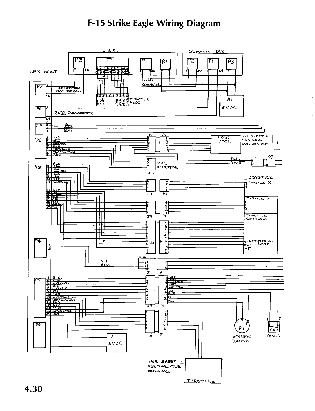
This page is a drawing, shown as the original scan.
F-15 Strike Eagle Wiring Diagram
SUPPLY TA cee SENSE
FoR cow oe ype |
eT [ams [r+
ToYSTICK rs Teysmxn X SEE SHEET 2 FOR |
TOYSTICK ¢ CENTERING
: ¢€ — SENSEITO
Tovercn ¥
a
Toysnoe ConviOs BOARD OIAGRAM
FA fe | ea fra
f CHASSIS GND fa 5 Fe CRASS IE. GND
4.31
F-15 Strike Eagle Wiring Diagram
conjorr Suneew
FLUORESCENT Liga,
4.32
4.33
EENTER DETECT
MISSILE TRIGGER TARGSEL
I [s"] “aEGseR CozrN DOOR
F-15 Strike Eagle Wiring Diagram
4.34 F-15 Strike Eagle Decals
080-0001-008 Joystick Decal
080-0001-007 Throttle Decal
080-00003-002 Start Decal 080-00001-006 F-15 Patch Decal
080-00003-001 Decoy Decal
EPROM and PAL Location Chart
| 110-00001-000 Host | U67 EPROM 120-00001-000 Host | U15 GAL | |
| 110-00001-001 Host | u91 EPROM 120-00001-001 Host | U59 GAL | |
| 110-00001-002 Host | U68 EPROM 120-00001-002 Host | U74 GAL | |
| 110-00001-003 Host | ug2 EPROM 120-00001-003 Host | U57 GAL | |
| 110-00001-004 Host | U69 EPROM 120-00001-004 Host | U56 | GAL |
| 110-00001-005 Host | U93 EPROM 120-00001-005 Host | U75 | GAL |
| 110-06001-006 Host | U70 EPROM 120-00001-006 Host | u77 | GAL |
| 110-60001-007 Host | ug4 EPROM 120-00001-007 Host | U76 | GAL |
| 110-00001-008 Host | u71 EPROM 120-00001-008 Host | U88 | GAL |
| 110-00001-009 Host | U95 EPROM 120-00001-009 Dr. Math | u79 | PAL |
| 110-00001-010 Host | u72 EPROM 120-00001-010 Dr. Math | U70 | PAL |
| 110-00001-011 Host | U96 EPROM 420-00001-011 Dr. Math | U118 PAL | |
| 110-00001-012 Host | U73 EPROM 120-00001-014 Dr. Math | uit1 PAL | |
| 110-00001-013 Host | U97 EPROM 420-00001-015 Dr. Math | U104 PAL | |
| 110-00001-014 Dr. Math | U153 EPROM 120-00001-016 Dr. Math | U138 PAL | |
| 110-00001-015 Dr. Math | U154 EPROM 420-00001-017 Dr. Math | U136 PAL | |
| 110-00001-016 Dr. Math | U167 EPROM 120-00001-018 Dr. Math | U109 PAL | |
| 110-00001-017 Dr. Math | U160 EPROM 120-00001-019 Dr. Math | U102 PAL | |
| 110-00001-018 Dr. Math | U135 EPROM 420-00001-020 Dr. Math | U59 | PAL |
| 110-00001-019 Dr. Math | U115 EPROM 120-00001-021 Dr. Math | U121 PAL | |
| 110-00001-020 Dr. Math | U108 EPROM 120-00001-022 Dr. Math | U122 PAL | |
| 110-00001-021 Dr. Math | U127 EPROM 120-00001-024 Dr. Math | U67 | PAL |
| 110-00001-022 Dr. Math | U134 EPROM 120-00001-123 Dr. Math | U116 PAL | |
| 110-00001-023 Dr. Math | u114 EPROM 120-00002-001 Video Graphics U45 | PAL | |
| 110-00001-024 Dr. Math | U107 EPROM 120-00002-002 Video Graphics U93 | PAL | |
| 110-00001-025 Dr. Math | U126 EPROM 120-00002-003 Video Graphics U87 | PAL |
110-00002-001 Video Graphics U101 EPROM 120-00002-004 Video Graphics U72 PAL 110-00002-002 Video Graphics U108 EPROM 120-00002-005 Video Graphics U79 PAL 110-00002-003 Video Graphics U114 EPROM 120-60002-006 Video Graphics U140 PAL 110-00002-004 Video Graphics U97 EPROM 120-00002-007 Video Graphics U40 PAL 110-00002-005 Video Graphics U124 EPROM 120-00002-008 Video Graphics U77 PAL 110-00002-006 Video Graphics U121 EPROM 420-00002-009 Video Graphics U86 PAL 110-00002-007 Video Graphics U130 EPROM 120-00002-010 Video Graphics U65 PAL 110-00002-008 Video Graphics U133 EPROM 120-00002-011 Video Graphics U56 PAL
| 110-00003-001 Sound | U17 EPROM 120-00003-001 Sound | uit | PAL |
110-00004-001 Sound U2 EPROM
Revision Level Explanation
Example: 110-00002-005
Revision Level
The software revision level is the MSB of the part number modifier. That means that part number 110-00002-105 would replace the above number and would be installed in the same location on the board.
4.35
NOTES
4.36
Frank Becker. © Cheri Glover.
Regan Cheng
Troy Dawson Jamie Stotz Gilbert Goodman
» Amarjit Sahni © Barbra Bents
Murray Taylor
Juanita Bussard
> John Emory
David Mar
Editor Designer and Illustrator Technical Illustrator Editorial Assistant Technical Assistant Parts Specialist Mechanical Engineer Contributing Artist Contributing Artist Contributing Artist Front Cover Design Front Cover Art
4.37
4.38
Warranty
Seller certifies that its printed circuit boards and parts thereon, and power supplies are free from defects in material and workmanship under normal operation for a period of ninety (90) days from date of shipment. Seller also certifies that its mechanical controls, (e.g. joysticks), and video displays are free from defects in material and workmanship under normal operation for a period of sixty (60) days from date of shipment. No other component or part thereof is warranted.
Sellers sole liability in the event a warranted part described above fails shall be, at its option, to replace, repair, or issue credit to the buyer for such products returned prepaid to sellers designated service center during the warranty period.
Should Seller determine, by inspection or ancillary information, that the product failure was caused by accident, misuse, neglect, alteration, improper repair, installation or testing, said warranty is void. In addition, use of non MicroProse Games parts may void warranty.
Under no circumstance is Seller liable for loss of profits, loss of use, or other damages.
This shall be the exclusive written warranty of the original purchaser expressed in lieu of all other warranties expressed or implied and shall under no
circumstance extend beyond the period of time listed
above.