Mr Do Run Run (no schematics)
Do! Run Run (set 1) (Universal, 1984) · Schematics · 22 pages · 16 sections · original scan
This page is a drawing, shown as the original scan.
This page is a drawing, shown as the original scan.
This page is a drawing, shown as the original scan.
This page is a drawing, shown as the original scan.
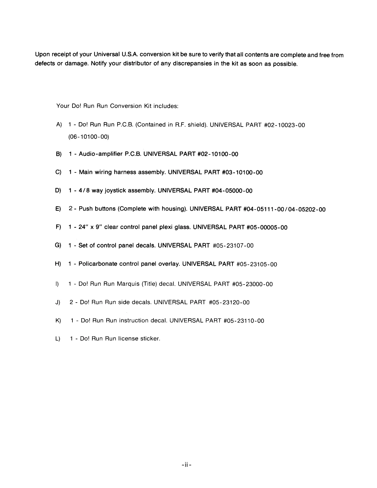
This page is a drawing, shown as the original scan.
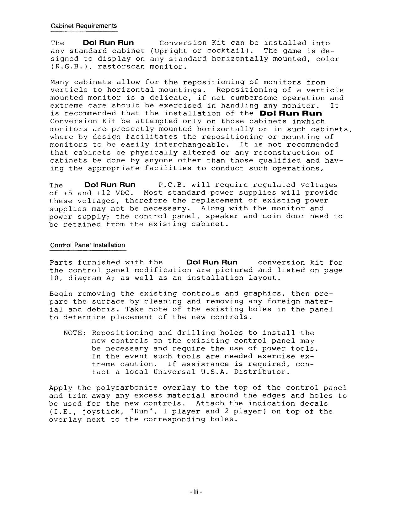
Cabinet Requirements
The Do! Run Run Conversion Kit can be installed into any standard cabinet (Upright or cocktail). The game is designed to display on any standard horizontally mounted, color (R.G.B.), rastorscan monitor.
Many cabinets allow for the repositioning of monitors from verticle to horizontal mountings. Repositioning of a verticle mounted monitor is a delicate, if not cumbersome operation and extreme care should be exercised in handling any monitor. It is recommended that the installation of the Do! Run Run Conversion Kit be attempted only on those cabinets inwhich monitors are presently mounted horizontally or in such cabinets, where by design facilitates the repositioning or mounting of monitors to be easily interchangeable. It is not recommended that cabinets be physically altered or any reconstruction of cabinets be done by anyone other than those qualified and having the appropriate facilities to conduct such operations,
The Do! Run Run P.C.B. will require regulated voltages of +5 and +12 VDC. Most standard power supplies will provide these voltages, therefore the replacement of existing power supplies may not be necessary. Along with the monitor and power supply; the control panel, speaker and coin door need to be retained from the existing cabinet.
Control Panel Installation
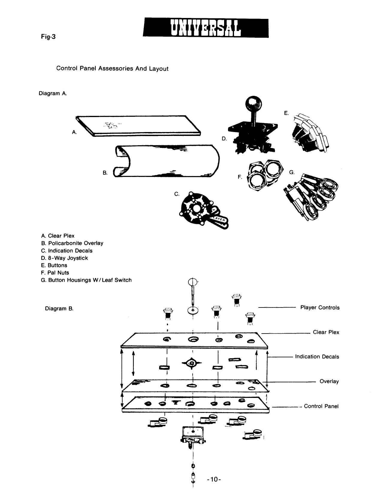
Parts furnished with the Do! Run Run conversion kit for the control panel modification are pictured and listed on page 10, diagram A; as well as an installation layout.
Begin removing the existing controls and graphics, then prepare the surface by cleaning and removing any foreign material and debris. Take note of the existing holes in the panel to determine placement of the new controls.
Apply the polycarbonite overlay to the top of the control panel and trim away any excess material around the edges and holes to be used for the new controls. Attach the indication decals (I.E., joystick, "Run", 1 player and 2 player) on top of the overlay next to the corresponding holes.
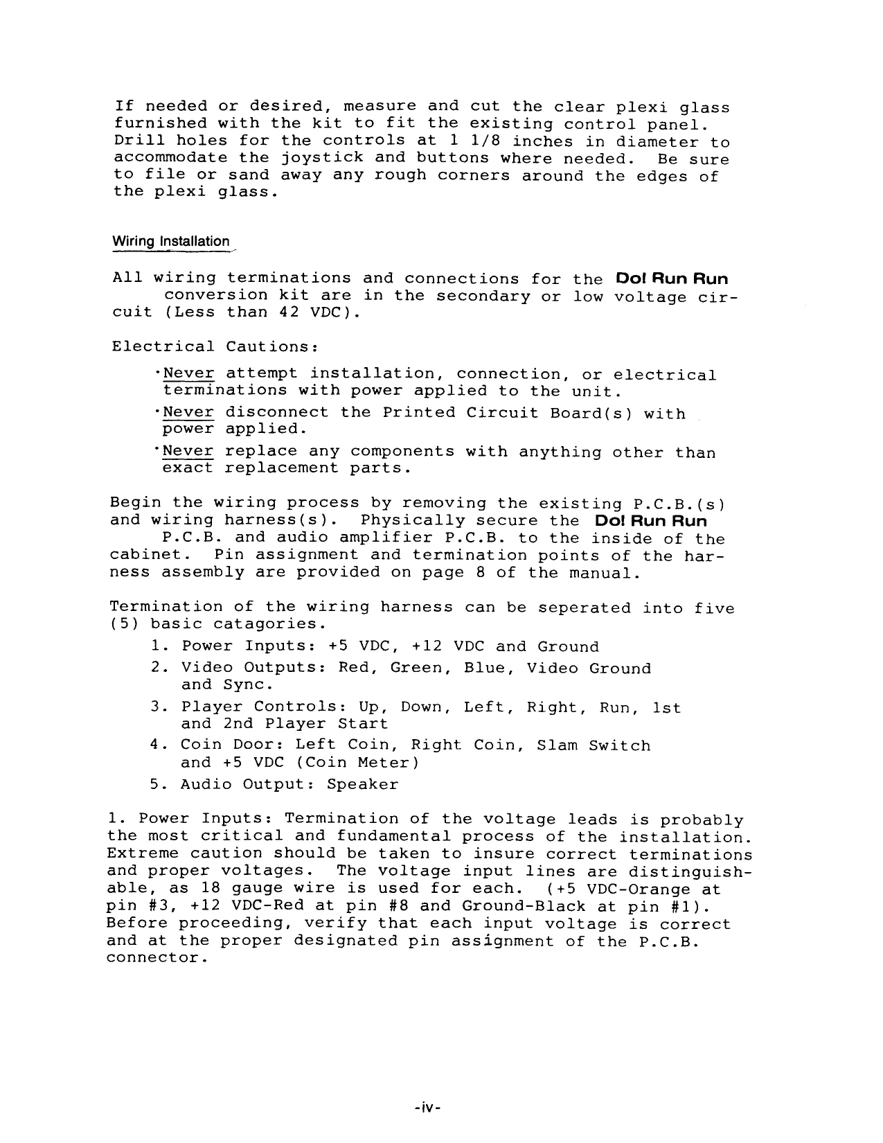
If needed or desired, measure and cut the clear plexi glass furnished with the kit to fit the existing control panel. Drill holes for the controls at 1 1/8 inches in diameter to accommodate the joystick and buttons where needed. Be sure to file or sand away any rough corners around the edges of the plexi glass.
Wiring Installation —
All wiring terminations and connections for the Do! Run Run conversion kit are in the secondary or low voltage circuit (Less than 42 VDC).
Electrical Cautions:
*Never attempt installation, connection, or electrical terminations with power applied to the unit. *Never disconnect the Printed Circuit Board(s) with power applied. "Never replace any components with anything other than exact replacement parts.
Begin the wiring process by removing the existing P.C.B.(s) and wiring harness(s). Physically secure the Do! Run Run P.C.B. and audio amplifier P.C.B. to the inside of the cabinet. Pin assignment and termination points of the harness assembly are provided on page 8 of the manual.
Termination of the wiring harness can be seperated into five
- basic catagories.
- Power Inputs: +5 VDC, +12 VDC and Ground
- Video Outputs: Red, Green, Blue, Video Ground and Sync.
- Player Controls: Up, Down, Left, Right, Run, lst and 2nd Player Start
- Coin Door: Left Coin, Right Coin, Slam Switch and +5 VDC (Coin Meter)
- Audio Output: Speaker
- Power Inputs: Termination of the voltage leads is probably the most critical and fundamental process of the installation. Extreme caution should be taken to insure correct terminations and proper voltages. The voltage input lines are distinguishable, as 18 gauge wire is used for each. (+5 VDC-Orange at pin #3, +12 VDC-Red at pin #8 and Ground-Black at pin #1). Before proceeding, verify that each input voltage is correct and at the proper designated pin assignment of the P.C.B. connector.
-iv-
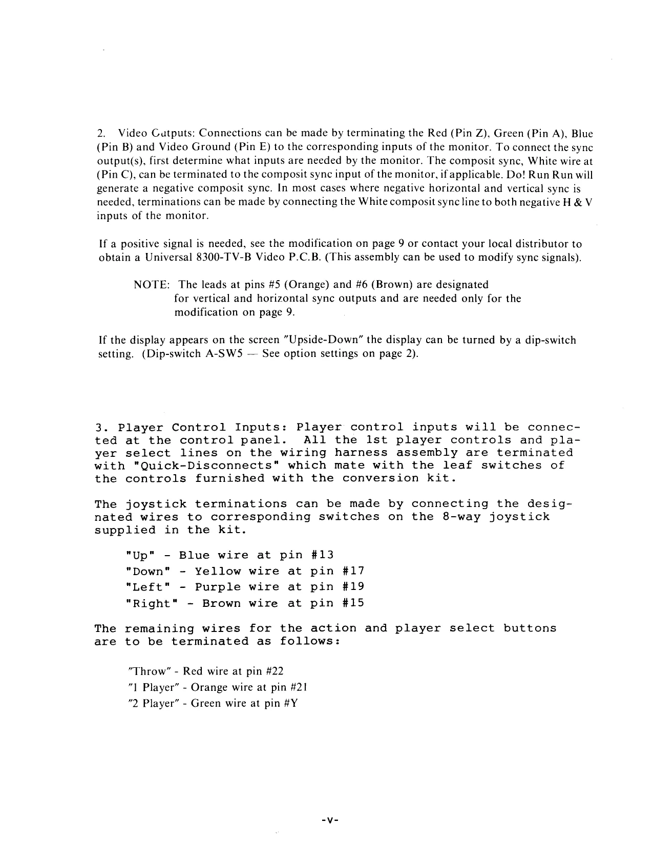
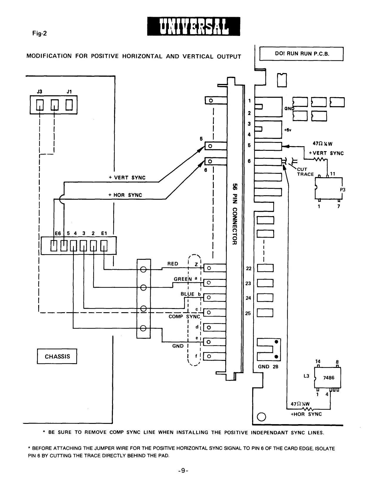
- Video Cutputs: Connections can be made by terminating the Red (Pin Z), Green (Pin A), Blue (Pin B) and Video Ground (Pin E) to the corresponding inputs of the monitor. To connect the sync output(s), first determine what inputs are needed by the monitor. The composit sync, White wire at (Pin C), can be terminated to the composit sync input of the monitor, if applicable. Do! Run Run will generate a negative composit sync. In most cases where negative horizontal and vertical sync is needed, terminations can be made by connecting the White composit sync line to both negative H & V inputs of the monitor.
If a positive signal is needed, see the modification on page 9 or contact your local distributor to obtain a Universal 8300-TV-B Video P.C.B. (This assembly can be used to modify sync signals).
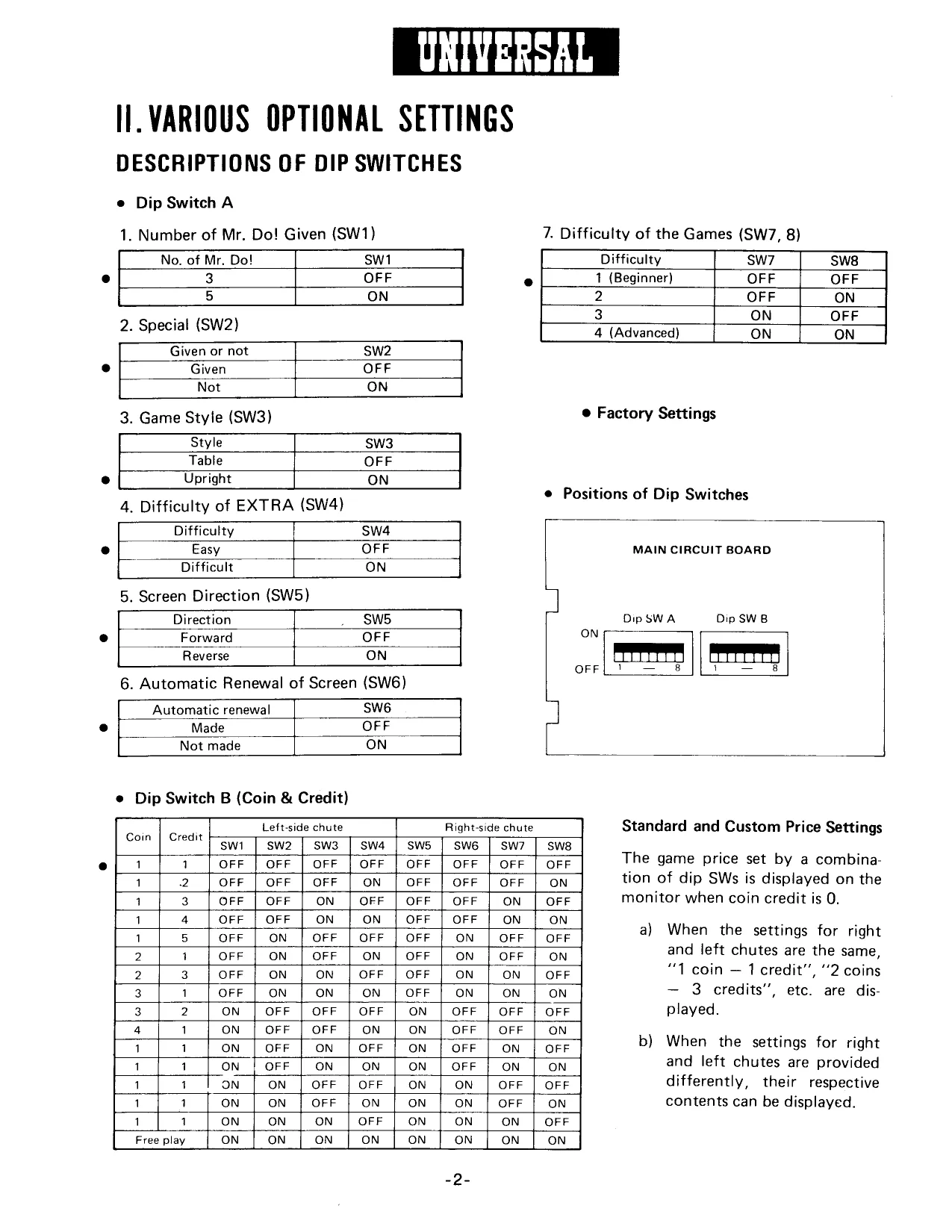
If the display appears on the screen “Upside-Down” the display can be turned by a dip-switch setting. (Dip-switch A-SW5 — See option settings on page 2).
- Player Control Inputs: Player control inputs will be connected at the control panel. All the lst player controls and player select lines on the wiring harness assembly are terminated with "Quick-Disconnects" which mate with the leaf switches of the controls furnished with the conversion kit.
The joystick terminations can be made by connecting the designated wires to corresponding switches on the 8-way joystick supplied in the kit.
"Up" - Blue wire at pin #13 "Down" - Yellow wire at pin #17 "Left" - Purple wire at pin #19 "Right" - Brown wire at pin #15
The remaining wires for the action and player select buttons are to be terminated as follows:
"Throw” - Red wire at pin #22 "| Player” - Orange wire at pin #21 "2 Player” - Green wire at pin #Y
-v-
The ground lead(s) for the controls are terminated and "daisy-chained" with eight (8) disconnects to be connected to the other contact of each leaf switch on the control panel.
The 2nd player control lines are unterminated and are only needed for a cocktail table installation, where two sets of controls are needed. Pin assignments can be found on page 8.
- Coin Door & Inputs: Wiring for the coin inputs can be accomplished by following either of the diagrams on the bottom of page 8. Seperate coin inputs are provided on pins #24 and #25 to allow for the selection of independent coin chute pricing (For options on price selection see page 2 - dip-switch B).
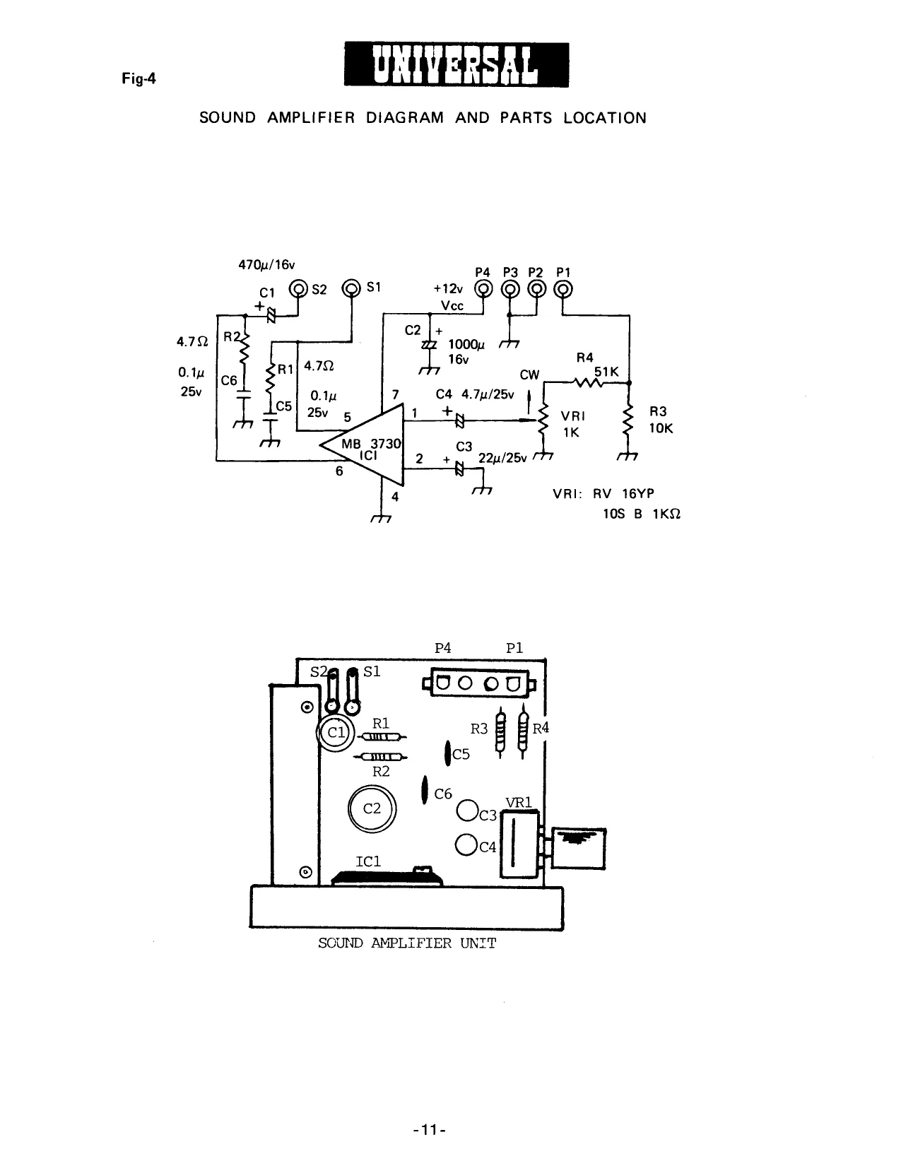
- Audio Outputs: Begin by soldering the speaker lines to terminals Sl (-) and S2 (+) on the audio amplifier P.C.B., then connect the audio plug on the harness assembly (White 4 pin molex) into the socket (pl-4) on the amplifier unit.
F.C.C. Warning:
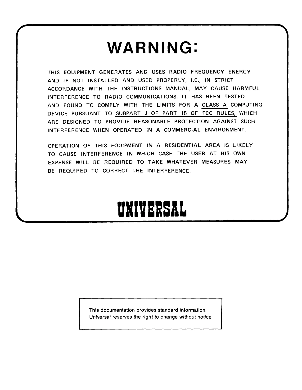
"This equipment generates and uses radio frequency energy and if not installed and used properly, I.E., In strict accordance with the instructions manual may cause harmful interference to radio communications. It has been tested and found to comply with the limits for a CLASS A computing device pursuant to SUBPART J OF PART 15 OF F.C.C. RULES, which are designed to provide reasonable protection against such interference when operated in a commercial environment."
"Operation of this equipment in a residential area is likely to cause interference in which case the user at his own expense will be required to take whatever measures may be required to correct the interference."
Mr. Do's Wild Ride P.C.B. is enclosed in a metal R.F. shield to meet the F.C.C. requirements stated above.
To comply with the ruling it is imparative that the R.F. shield is installed properly. After mounting, make sure that the cage is GROUNDED. With an Ohm meter, conduct a continuaty test between the shield and ground, to verify proper installation. Enclosed in the conversion kit is an F.C.C. Warning Sticker. This decal MUST be placed and maintained on the exterior of the cabinet.
Under NO circumstances should this equipment be operated without the Printed Circuit Board properly installed in the R.F. shielding
-vi-
This page is a drawing, shown as the original scan.
This page is a drawing, shown as the original scan.
This page is a drawing, shown as the original scan.
This page is a drawing, shown as the original scan.
This page is a drawing, shown as the original scan.
This page is a drawing, shown as the original scan.
This page is a drawing, shown as the original scan.
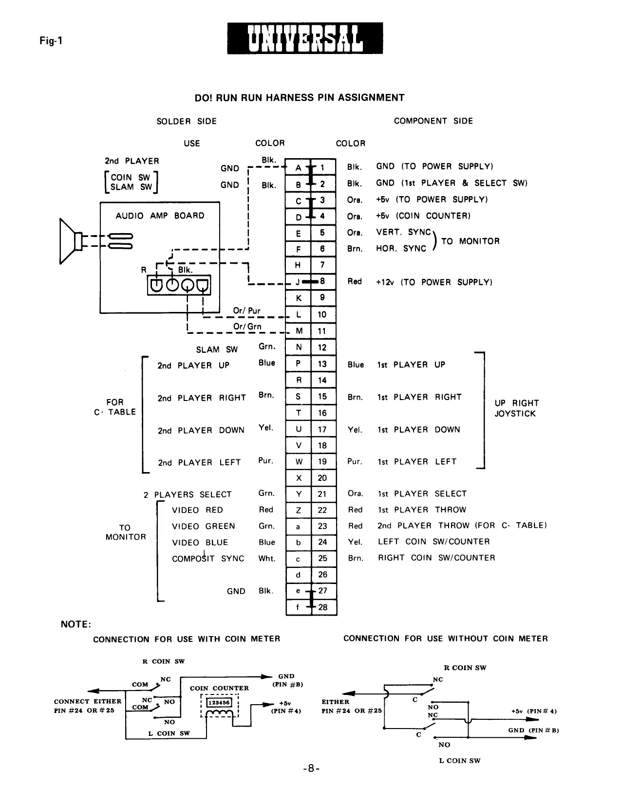
DO! RUN RUN HARNESS PIN ASSIGNMENT
SOLDER SIDE COMPONENT SIDE
| USE | COLOR | COLOR |
and PI Bik. oh PLAYER: Blk. GND (TO POWER SUPPLY)
COIN SW [Som | Bik, GND (1st PLAYER & SELECT SW) Ora, +5v (TO POWER SUPPLY)
Ore, +6v (COIN COUNTER)
Ore, VERT. SYNC ) 10 MONITOR Brn. HOR. SYNC
Red +12v (TO POWER SUPPLY)
Looe Or/Grn
SLAM sw Grn.
| 2nd PLAYER UP | Blue | Blue 1st PLAYER UP |
Brn. Bi
| FOR | 2nd PLAYER RIGHT | mm. Ist PLAYER RIGHT | UP RIGHT |
C: TABLE JOYSTICK
2nd PLAYER DOWN Yel. Yel. 1st PLAYER DOWN
2nd PLAYER LEFT = Pur. Pur. Ist PLAYER LEFT
| 2 PLAYERS SELECT | Grn. | Ora. 1st PLAYER SELECT | |
| VIDEO RED | Red | Red Ist PLAYER THROW | |
| To | VIDEO GREEN | Grn. | Red 2nd PLAYER THROW (FOR C- TABLE) |
| montron | VIDEO BLUE | Blue | Yel. LEFT COIN SW/COUNTER |
COMPOSIT SYNC Wht. Brn, RIGHT COIN SW/COUNTER
GND Bik.
CONNECTION FOR USE WITH COIN METER
R COIN sw
GND «PIN #8)
CONNECT EITHER PIN #24 OR #25 +5v (PIN #4)
L COIN sw CONNECTION FOR USE WITHOUT COIN METER
R COIN SW
NC
EITHER e PIN #24 OR #25 NO ne +5v (PIN# 4)
GND (PIN #8) "NO
L COIN SW
This page is a drawing, shown as the original scan.
This page is a drawing, shown as the original scan.
This page is a drawing, shown as the original scan.
This page is a drawing, shown as the original scan.
This page is a drawing, shown as the original scan.