Ice Cold Beer
Ice Cold Beer (set 1) (Taito, 1983) · Manual · 58 pages · 22 sections · original scan
Trade Marks of Taito America Corporation 72-00041-001

This page is a drawing, shown as the original scan.
Reproduction of this publication is forbidden without the written permission of TAITO
AMERICA CORPORATION, Elk Grove Village, Illinois. This manual is only conditionally
issued, and neither receipt nor possession thereof confers or transfers any right in, or
license to use, the subject matter of the manual or any technical information contained
thereof.
For permission requests, write: TAITO AMERICA CORPORATION 1256 Estes Avenue Elk Grove Village, Illinois 69007 Telephone (312) 981-1000 Telex 25-3290
This page carries no recoverable text. It is a drawing or a photograph. See the original scan.
“ICE COLD BEER”™ TABLE OF CONTENTS
“ICE COLD BEER”™ GAME SET-UP Page 3.4 Adjustments .............. 12 3.4.1 Playfield Hole Switches .... 2... 13 1.1 Game Features .........,... 1 3.4.2 Ball Gate Switth .. 2... ..... 13 1.2 Introduction. .. 2... 2. 1 3.4.3 Errant Ball Switch .......... 13 1.3. Game Inspection ........... 1 3.4.4 Motor Limit Switches ......... 13 1.4 Pre Game Installation... 2... 2. 1 3.4.5 Ticket Vendor (Optional)... ..... 13 1.5 Power Requirements... ....... 1 3.4.6 Volume Control... ...-...05 13 1.6 Power On/Off Switth ......... 1 1.7 Coin Meters..........0... 1 ILLUSTRATION & PARTS LISTS 1.8 Test and Alignment Procedure Electrical Test... 2... wa 1 Figure 1 Power On/Off Switch ....... 1 1.8.1 Hole Test 1 Figure 2 Dip Switch Settings. ....... 2 1.8.2 Bar Test 1 Figure 3 Fuse Replacement ........ 5 1.8.3 Erant Ball Test. .......-...- 2 Figure 4 Pulley Lubrication. ........ 5 1.9 Dip Switch Settings... 2... 2,3 Figure 5 Ball Rod Lubrication ....... 5 Figure 6 Playfield Removal. ........ 5 MAINTENANCE Figure 7 Coverglass Removal. ....... 6 Figure 8 Printed Circuit Board Removal... 6 2.1 Cleaning ... 2... 0.2... 2002 5 Figure 9 Playfield Switches. ........ 11 2.2 CoinDoor............00. 5 Figure 10 Ticket Vendor... ........ 13 2.3 Fuse Replacement 5 Figure 11 Volume Control .....-.... 13 2.4 Lubrication Of Mechanical Parts 5 Figure 12 Test Point Wave Forms .... 14,15 2.5 Playfield Removal. ...... 5 Figure 13 Diagnostic Test Wave Forms... . 15 2.6 Coverglass Removal .......... 6 Figure 14 Fluorescent Panel... ...... 19 2.7. Printed Circuit Board Removal. ... . 6 Figure 15 Playfield Rear View ...... 20,21 2.8 Power Supply Voltage Test Points ... 6 Figure 16 Cabinet Rear View ...... 22,23 Figure 17 Power Supply... ...... 24,25 THEORY OF OPERATION Figure 18 Coin Dor .......... 26,27 Figure 19 Control Panel & 2 Way Joystick. 28,29 3.1. “Ice Cold Beer”™ Game Operation ... 8 Figure 20 Playfield Front View... . . . 30,31 3.2 Circuit Description ...... Figure 21 Cabinet Front View ..... . 32,33 3.2.1 Power Supply... 1... +. Figure 22 Unregulated Power Supply. . . 34,35 3.2.2 Logic And Regulatior Board . Figure 23 Motor Pulley Assembly 36,37 3.3 Self Diagnostic te Figure 24 Solenoid Assembly ..... . 38,39 3.3.1 Test O: 8279 Display Test (U29) . . 10 Test 1: Eprom Checksum ...... 10 Test 2: Ram Excersise........ 11 Test 3: Joystick/Limit Switch Inputs . 11 Test 4: 8279 Switch Inputs Scan O . 11 Test 5: Switch Inputs Scan 1 .... 11 Test 6: 8279 Switch Inputs Scan 2 . 11 Test 7: Motor Control Port. ..... 12 Test 8 & 9: Control and Data Ports . 12 Test 10: 8910 Output Port Test... . 12 Test 11: U10 Sound Test... .... 12 Test 12: U9 Sound Test ....... 12 Figure 25 Logic & Regulator Board Component Layout ...... 40-42 Figure 26 Ice Cold Beer Playfield Readout Board .......... 43 Figure 27 Wiring Diagram 3 of 3 1... . 44 Figure 28 Wiring Diagram lof 3 ...... 45 Figure 29 Wiring Diagram 2 of 3... ... 46 Figure 30 Power Supply Schematic .... . 47 Figure 31 Circuit Board Schematic 1 of 3. . 48 Figure 32 Circuit Board Schematic 2 of 3. . 49 Figure 33 Circuit Board Schematic 3 of 3. . 50
Game Set
- GAME SET-UP 1,1 GAME FEATURES TAITO AMERICA CORPORATION'S “ICE COLD BEER”™ game operates on a simple electro-mechanical mechanism,which makes it reliable and easy to service. A larger security designed cash box has been incorporated into the design of this cabinet. The Control Panel has a polycarbonate overlay, so cigarette marks and mars can easily be wiped clean. This overlay can be replaced if necessary. The Coverglass is made of fully Tempered Glass to minimize breakage. The Back Service Door is fully removeable making servicing of the game easier. Leg levelers are installed on the game. An Optional Ticket Dispenser is available. For further information contact Taito America Corporation’s Customer Service Department in Elk Grove Village, Illinois. 1.2 INTRODUCTION TAITO AMERICA CORPORATION is pleased to introduce “ICE COLD BEER”™ the most challenging game to hit the market in years. The object of the game is for the player to maneuver the ball with the joysticks that moves the bar to position the ball in the lit hole. Each side of the bar can be moved independently to position the ball. The vertical playfield is filled with non lit holes so you must use ail your skills to position the ball to go in the right lit hole. The easier lit holes are at the bottom of the playfield so you have to have steady concentration to reach the top hole. ICE COLD BEER™ has several features like our self prompt feature. If you take too long to move the bar it will begin on its own. It also has a tilt feature and a Bonus feature. If the game is tilted in any way the ball in play will be lost. The Bonus feature allows you to start out with bonus points and the quicker your ball goes in the lit hole the more bonus points you receive. 1.3 GAME INSPECTION TAITO AMERICA CORPORATION'S “ICE COLD BEER”™ game is shipped ready for operation, but a last visual check should be made to insure the game is in good condition. Please verify the following before turning the game on. *Check the exterior of the game for shipping damage, chips, dents or broken parts. *Open the Rear Service Door and check for any interior damage. *Make sure there isn’t any damage to the wiring. *Check the printed circuit board, making sure there is no damage to the components.
- Check fuses making sure they are firmly in their holders. *Check for loose foreign objects, especially metal objects which may cause electrical problems. *Check Plug-in Connectors making sure they are firmly in their sockets. *Check the Coin Door for any possible damage, especially the switches. 1.4 PRE GAME INSTALLATION ICE COLD BEER™ has leg levelers which should be adjusted before your game is ready to play. Be sure you readjust the leg lev ers whenever you move the game from one location to another. Since the ball is shipped separately,you will have to take the ball out of the shipping package and place the ball into the hole at the upper right hand corner of the playfield background. 1.5 POWER REQUIREMENTS TAITO AMERICA CORPORATION'S “ICE COLD BEER”™ game is shipped ready for operation at 120VAC, 60 Hz with a power consumption of approximately 100 Watts. 1.6 POWER ON/OFF SWITCH To minimize the hazard of electrical shock while servicing the game, a Power ON/OFF Switch has been provided.This switch is located in the lower right front of the cabinet. Refer to Figure 1.
Ss SS
1.7 COIN METERS This game is equipped with one coin meter inside the cash box. 1.8 TEST AND ALIGNMENT PROCEDURE ELECTRICAL TEST The hole test is to test the lit holes to make sure they light in the right sequence. The bar test is to insure the bar will travel the entire playfield without binding. The Errant Ball test is to test the errant ball switch and soleloid to make sure they function properly. Follow the instructions below before performing each of these test.
- Open the Coin Door and unlatch the Control Panel, tilt the Control Panel forward and remove the playfield glass. Refer to Section 2.6.
- Turn the game on and credit the game. Push play button. 1.8.1 HOLE TEST Wait until the music and bar stops at the starting position and then place the ball in the lit hole. Make sure that the points tally properly if not the display will say “OOPS”. Repeat until all ten holes have been tested. If theOOPS” is displayed adjust the appropriate switch. 1.8.2 BAR TEST With the ball off the bar run the bar up and down the playfield using the appropriate joystick to insure that the upper and lov limit switches engage properly.
1.8.3 ERRANT BALL TEST Drop the ball in the bottom most hole making sure that “OOPS” is displayed and the ball returns to the ball gate. 1.9 DIP SWITCH SETTINGS
iS s SI = ny
LC] jogoo000 = 000000 CL)
#5 4
© GSSNSdSIG SLIHOILON | 0 G3SNSdSIO SL3OILON | 0 | GASN3dSIC SLIYOLL ON OL FTOH HALA SLAMOIL 9 3TOH YALA SLAMOLL 2 OL —S$ SA1OH HALAV LAXOIL | S$ AT1OH HALAV SLAMOILS qalavsid
NOILdO
~~ NOIlLdO SSNadSIG EMS ooo] Jofojolo]= oJ oo 7 Oo ° 0 FIOH HALA SLAMOILS | 0 | by) ° €
t=O 2@=9 110349 Yad SNIOO ——————F Tivd VHLXa ON
Te mre Od SHOOS Piss Toto Pnors [obo Passes [2 d34dS NMOGLNNOS SNNO «N3dO,» =O |
«03SOT9, = G@a1aVNa = NadO aatavsid = a3s010 ATEVNA SGOW LOVYLLY OILYVWOLNY SAWVus 2 = NadO aWvu4 | = d3s010 YVLS LHD! OL SLAId WOO OL SGNNOY St (oe) ol o| 9 CNIW) AV13d 30OW LOVELLV OLLWWOLNY
"NIW CNIW) AV14d SCOW LoVeLy IWANWW “OAS, SWIL LdWOud. ALINOIssIG «4AO, 410 .NAdO. = «NO, 40..d4SO019,=9 |
Maintenance
ALL GAMES REQUIRE A CERTAIN AMOUNT OF MAINTENANCE TO KEEP IT IN GOOD WORKING ORDER. A PERIODIC CHECK OF THE MECHANICAL CONTROLS WOULD BE BENEFICIAL TO THE SUCCESS OF YOUR GAME.
- MAINTENANCE 2.1 CLEANING The exterior of the game, all metal parts and all plastic parts can be cleaned with a non-abrasive cleanser. Caution should be used when cleaning the glass, a dry cloth can cause scratches and result in a foggy appearance. 2.2 COIN DOOR The Coin Door in “ICE COLD BEER”™ game needs little or no maintenance. If desired, a special coin mechanism cleanser that leaves no residue, can be obtained from your distributor.
2.3 FUSE REPLACEMENT This game contains (5) fuses. All five of these fuses can be found on the Power Supply Assembly. Refer to Figure 3 for the location of these fuses.
FUSE 1.5AMP 3AG SLO BLO & 24-00002-002
Vv FUSE 6 AMP
y 24-00003-006 FUSE 4.0 AMP ‘ 24-00003-004
i : FUSE 2.5 AMP | 24-0000 3-002
2.4 LUBRICATION OF MECHANICAL PARTS To insure a minimum of maintenance on this game a periodic lubricating of the mechanical parts is required. PULLEY LUBRICATION Lubricate the upper pullies every 60 days using a multi- service lithium grease. See Figure 4.
Grease the shaft. BALL ROD LUBRICATION Lubricate the ball rods every 60 days using silicone.
Ball Rod Lubrication 1, Remove the coverglass. Refer to coverglass removal section 2.6.
- Extend rods diagonally as shown in Figure 5.
- Put the silicone on a clean cloth and then rub the cloth over the bail rods.
- Remove the playfield by removing the four harness connectors and the playfield readout connector.
- Unscrew the two wing nuts on the bottom of the playfield.
- Slide the playfield out by lifting the bottom out and down.
- Slide the playfield out until the upper retaining brackets are free and then remove it from the cabinet.
=
2.6 COVERGLASS REMOVAL Refer to Figure 7.
ar To remove the coverglass follow the directions listed. Open the Coin Door. Unlock the Control Panel by releasing the two latches. Lift the Control Panel up and place vertically in front notches below the control panel. Place hands under the coverglass and lift up and out until glass come to rest in the rear notches under the control panel. Tilt the coverglass out from the top and lift out. 2.7 PRINTED CIRCUIT BOARD REMOVAL To remove the printed circuit board simply follow the instructions listed.
- Turn power off. 2, Remove the rear service door.
- Disconnect the connectors from the boards.
- Loosen and turn the stop bracket and lift the boards out of the board guides.
)
2.8 POWER SUPPLY VOLTAGE TEST POINTS These voltages are measured across the test points, on the power supply board indicated, not to the chassis. Voltages are taken in the attract mode with the motors stationary. TP1-TP2 live TP3-TP4 14vbc TPS - TP6 evDct TP7 -TP8 32vpct* These voltages are unfiltered DC. The response charecteristic of the meter will effect the reading.
Operation
THIS SECTION PROVIDES A TECHNICAL DESCRIPTION OF ICE COLD BEER™ GAME.
- THEORY OF OPERATION
3.1 ICE COLD BEER™ GAME OPERATION The game objective is to move the ball up the playfield using the motorized bar and roll it into the illuminated target hole. There are ten numbered target holes amongst many trap holes. The target is advanced as the player successfully reaches the illuminated hole. The star on the score board is illuminated when the player finishes the tenth hole. The start button flashes after the game is coined. When the START button is pushed the bar decends, opening the gate, and releasing the ball. The bar then rises to the “Start” position on the playfield. During this time the joysticks are disabled. The bonus for the target appears on the scoreboard. The bonus begins decrementing when a joystick is moved or after 10 seconds if no action is taken. A “heart beat” sound is heard during countdown followed by a “straight-line” sound if the bonus reaches the minimum. When the target is reached the remaining bonus points are added to the player's score. The countdown rate is adjustable via the dip switch. Should the joysticks be inactive for a while the bar will automatically begin stepping upward. The stepping rate is adjustable via the dip switch. After playing through the first frame (all 10 target holes) the scoreboard star is Jit and play continues at HOLE 1. Game difficulty is increased by shortening the time from the last joystick command and the onset of automatic bar stepping. The difficulty increases with each frame. If the ball is not at the gate (BALL GATE SWITCH open) when the game starts the search program will be initiated. The bar will sweep the playfield and the ERRANT BALL SOLENOID will be pulsed. The search ends when the ball closes the ball gate switch. The search program will terminate and the “OUT OF ORDR” message will be issued if the ball is not found. When the ball falls below the bar (usually by bouncing out of a trap hole on it’s way down) it is funneled to a hole at the bottom of the playfield. Upon entering the hole the ball activates the ER- RANT BALL SWITCH and comes to rest over the ERRANT BALL SOLENOID. The sclenoid then kicks the ball up to the gate closing the BALL GATE SWITCH. Each target hole is monitored by a switch. These switches are part of a scanned switch matrix including the tilt/slam, coin, start, ball gate, errant ball, ticket vend, hopper cycle, hopper empty, and free play switches. Each switch must be closed for at least 20ms to be recognized. When a switch is replaced it must be adjusted to meet this requirement. See Figure . The ticket vendor (optional) dispenses at user selectable target levels, Tickets are loaded and the vendor adjusted using the TICKL VEND switch inside the coin door. When the ticket hopper is empty the game issues the “OUT OF TICS” message,a warning sound, and disables the attract mode. The game will continue to accept coins and play. At the ticket vend points the warning sound will be heard. 3.2 CIRCUIT DESCRIPTION The electrical portion of the game consists of a Logic and Regulator circuit board and an unregulated power supply. 3.2.1 POWER SUPPLY The unregulated power supply is located on the floor of the cabinet. This assembly contains the line filter, power transformer, fuses, rectifiers and filter capacitors. The power supply provides the following: 12V @ 2.5 Amps unregulated, for motors, sound and display. QV @ 2.0 Amps unregulated, to supply the 5V regulator. 6V @ 2.0 Amps unregulated, unfiltered for lamps. 25V @ 2.0 Amps unregulated, unfiltered for the solenoid. The four supply sections have no common ground on the supply chassis. THE COMMON GROUND IS ESTABLISHED ON THE LOGIC. AND REGULATOR BOARD. 3.2.2 LOGIC AND REGULATOR BOARD The game is controlled by a 68A09E microprocessor unit (MPU) and associated support logic. All logic and the 5 volt supply regulator reside on a single printed circuit board located on the jower rear cabinet panel. The power supply return lines (QRTN,12RTN,6RTN, 25RTN) are commoned at connector J3 pins 3,4,5, and 6. The MPU operates on a 1.5 MHz 2-phase clock. The 6 MHz crystal oscillator output is divided by U5 to generate tne E and Q clock signals. The power-on RESET signal is generated by voltage comparator U1 (pins 2,4,5). When power is first applied the 2.5V REF is established quickly while C110 charges slowly through R37. During this period U1-2 (RESET)is high and U22-8 (RESET/) is low. After 50mS the voltage across C110 exceeds 2.5V driving U1-2 low and U22-8 high. C110 is discharged quickly through D1 when power is removed. The game program is contained in 2764 EPROMS U23 and U24. U25 is not currently used. The EPROMS are permanently chip selected. The output enables are selected by address decoder U16. The 2128 RAM U13 is permanently chip selected. The output and write enables are driven by address decoder U14, The “TEST” switch SW1 and U1 (pins 1,6 and 7) toggle the NMI/ line to enter the system diagnostics program. R35 provides Positive feedback to debounce SW1.
The PIA U27 and J4 are currently unused. The PIA U26 is an input port for the JOYSTICK and LIMIT switches from J1 and the configuration DIP switch SW3. U26 also provides an output signal, LPFON/, and an interrupt input for the SWIRQ signal. These will be discussed later. The audio power amplifier U38 drives the speaker. U38 is mounted on a heat sink. The 9V power supply is regulated to 5V by U11. The regulator is mounted on a heatsink. The heatsink and regulator case are at ground potential. The PIA U28 is the MPU interface to the sound generators U9 and U10. The bi-directional data lines of the sound bus (SDO-SD7) are connected to the “A” port of U28. The “B" port drives the sound bus control lines CONO-CONS. U28 also provides an interrupt input for the “SINT” signal. This will be discussed later. The sound generator IC's, U9 and U10, each provide three square wave analog audio outputs and two 8-bit TTL bi-directional VO ports. The audio outputs of U9 are summed across R69 to generate SOUND1. The two I/O ports are buffered by U2, U7 and U15 to drive various lamps and counters. The output buffer IC'S are open collector types capable of sinking 500mA. The COINLOCK/and EBSOL/outputs require greater current and are buffered by Q1 and Q2. Bit 7 of I port A is the source for TIMERST/which controls the WATCHDOG TIMER (described later). During reset all 1/0 port lines are set high. The output of port “B” is disabled after reset by U8 until MOTENBV/is driven iow. This prevents spurious coin counts during power-up. The CH-A and CH-B audio outputs of U10 are summed across R68 to generate SOUNDO. The CH-C output is translated to TTL levels by Q3 and becomes HZ30. The edges of HZ30 are sharpened at U17-8 to insure the proper rise time for the clock input U17-3. HZ30 is divided by two at U17-5 to form SINT which is applied to U28-40. SINT is a 15Hz signal used to generate 67msS interrupts (FIRQ)) for software timekeeping. The “A” \/O port reads the configuration switch SW4. The “B” 1/0 port is buffered by U3 and U4 to drive various lamps. Bit 7 of this port generates the MOTENBL/ signal which inhibits the motors and coin counters during power-up. U33 is a four-section Norton amplifier used to filter and combine the audio signals SOUNDO and SOUND1. SOUND1 is applied to two sections of U33. One of these (U33 pins 1,5,6) is a 2-pole, unity-gain, 500Hz low-pass filter. The other section (U33 pins 2, 3,4) is a flat unity-gain amplifier. The outputs of these two stages are combined at the junction of R97 and R98. Each stage is active when the bias voltage (BUFBIAS or FILBIAS) is approximately 2.7V. Stages are similarly inactive when the bias is 12V driving the amplifier into saturation. The bias sources are controlled by LPFON/ from U26. When LPFOW/ is low, U21-12 is pulled to ground setting FILBIAS to 2.7V while U22-2 is open circuit setting BUFBIAS to 12V. SOUND1 is then passed through the filter. The converse is true when LPFOW/ is high. SOUND1 is then unfiltered. SOUNDO is passed through a 6KHz, 2-pois. low-pass filter (U33 pins 10,11,12) and added to SOUND1 through R104. The sum is buffered by U33 (pins 8,9,13) to form the AUDIO signal applied to the power amplifier. Each motor is driven by a bridge amplifier made up of NPN and PNP darlington power transistors driven by open- collector drivers. Logic circuits insure that the two transistors of a bridge-half can never be energized simultaneously. For example, to drive the left motor in one direction LORIVE1/ and LDRIVE2/ are set low, LDRIVEO/ AND LDRIVE3/ set high. Q8 and Q17 are then turned on and Q9 and Q16 tumed off driving LMOTOR to 12V and LMOTOR? to ground. To reverse the motor LD- RIVEO/ and LDRIVE3/ are set low, LDRIVE1/ and LDRIVE2/ are set high driving LMOTOR to ground and LMOTOR/ to 12V. If LDRIVEO/ and LDRIVE/2 are set low U36-1 will go high forcing both U32-3 and U32-6 high thus preventing Q8 and Q16 from turning on. Motor control signals are latched by U35. The latch command comes from the output of address decoder U34-8. The motor port output is disabled (motor off) when MOTENBL/ is high (during reset), The keyboard/display IC, U29, drives the eight digit display and reads all switches apart from the joysticks and limits. Three scan lines from U29-32,33,34 are decoded by U19 to activate the digit drivers Q4-Q7 and Q12-Q15. The same three scan lines are decoded by U20 to drive the switch matrix drivers SCANO/-SCAN2/ and STROBEO/. IOR/ and tOW/ signals for U29 are generated by U30-3 and U30-11. The chip select is generated by U35-6. The returns from most of the scanned switches are connected to SENSEO/-SENSE6/. These switches cannot close simultaneously. Several switches may close at the same time as these and are therefore isolated by diodes D3-D7, D11 and D12. The HOPSTOP/ switch closes to ground and cannot be scanned directly. The STROBEO/ signal is used with U31 (pins 1,2,3) to gate HOPSTOP/ into U29. The scanned switches are not recognized unless they are closed longer than 20mS. Tilt switch closures are lenghtened to 50mS by the pulse stretcher U1 (pins 10,11 and 13). The output is gated into U29 by STROBEO/ and U31 (pins 4,5, and 6). U39 is a WATCHDOG TIMER which will restart the game should the MPU be upset by power line noise or static discharge. Under normal operation a 5uS TIMERST/ pulse will be generated by software during each SINT interval (67mS). This pulse is output at U9- 14 and triggers section 1 of dual timer U39. The pulse is stretched to 8mS-at U39-5 and keeps C166 discharged through Q20. Section 2 of U39 is a 1.1Hz square wave oscillator whose output U39-9 will remain high as long as C166 is discharged. Should the MPU loose contro! the TIMERST pulses will cease allowing C166 to charge. Approximately 450mS later a RESET/ signal will be generated at U39-2. When RESET/ goes high the system must begin issuing TIMERST/ pulses within 380mS or another RESET/ pulse will be generated. The cycle will continue until the system restarts successfully.
3.3 SELF DIAGNOSTIC
ADDRESS DATA
$4081 $04 $4081 $2F $4081 $C2 $4081 $90 $4080 SEGMENT DATA (WRITTEN 8 TIMES)
$4080 SEGMENT DATA The segment data written represents A-F in data bits DO through D7 respectively with logic 1 corresponding to an i!luminated segment.
DISPLAY BUS DATA
$3F $06 $5B $4F $66 $6D $7D $07 $FF $67 OHMUNMRARWNKHHO TEST 1: EPROM CHECKSUM Test 1 computes a checksum for each EPROM. The data content of each EPROM has been arranged to produce a specific result for this test. There are two EPROMs on the logic board, U23 and U24. When it completes the test, the diagnostic displays an “F” for each failing EPROM or a “P” for each passing EPROM in the SCORE display. The left most digit represents the U24 EPROM and the right most the U23. The BONUS display will show the test number, in this case a “1”. After completion, this test continues to repeat until the test switch is pressed.
TEST 2: RAM EXERCISE The RAM test writes an incrementing data value into each RAM location from its origin ($0) to its end ($7FF). It then goes back and rereads the RAM comparing the data read with what was written at that address previously. Each pass begins by writing different data at $0, thus 256 passes are used to completely exercise the RAM. If 256 successful passes are completed, a “P” and the final address 0800 is displayed and the exercise stops until a power on reset or another test switch closure. If during the test, the data read back does not match the data previously written, an “F”, the hexadecimal address at which the failure was detected, and the EX- CLUSIVE-OR of the written and read data is displayed. Diagnostic then loops on alternate reads and writes to the failed address until released by reset or another test switch closure. Test 2 requires about 10 seconds to complete during which the pass number is displayed. \t may be interrupted at any time without damage by depressing the test button for the next test. TEST 3: JOYSTICK/LIMIT SWITCH INPUTS. Test 3 displays its test number in the bonus display and repeatedly reads the joystick and limit switch inputs on the PIA addressed at $4010. The data is complemented and displayed as hex in the lower two digits of the score display. The hex value displayed for a single switch closure is as follows:
SWITCH BIT POSITION DISPLAY
| Right Down Limit | 00000001 | 0001 |
| Right Joystick Down | 00000010 | 0002 |
| Left Down Limit | 00000100 | 0004 |
| Left Joystick Down | 00001000 | 0008 |
| Right Up Limit | 00010000 | 0010 |
| Right Joystick Up | 00100000 | 0020 |
| Left Limit Up | 01000000 | 0040 |
| Left Joystick Up | 10000000 | 0080 |
TEST 4: 8279 SWITCH INPUTS SCAN 0 Test 4 displays its test number in the bonus display then reads the switches from the 8279 in its sensor matrix mode. During this time, The 8279 will scan all three rows of switches continuously and report to CPU the data returned to its sense inputs during the scan O time. The scanned row number (0) will be displayed in the two low digits of of the score display and the sensed input data will be displayed in hex in the two high digits. The switches, bit position, and displayed values for a single switch closure are as follows:
| SWITCHES | BIT POSITION | DISPLAY |
| Start switch | 00000001 | 0100 |
| Coin switch | 00000010 | 0200 |
| Ball Gate switch | 00000100 | 0400 |
| Tilt switch | 00001000 | 0800 |
| Free Play Service | 00010000 | 1000 |
| Hopper cycle sensor | 00100000 | 2000 |
| Hopper empty (optional) | 01000000 | 4000 |
TEST 5: SWITCH INPUTS SCAN 1 Test 5 displays its test number in the bonus display then reads the switches from the 8279 in its sensor matrix mode. During this time, the 8279 will scan all three rows of switches continuously and report to the CPU the data returned to its sense inputs during the scan 1 time. The scanned row number (1) will be displayed in the two low digits of the score display and the sensed input data will be displayed in hex in the two high digits. The switches, bit positions, and displayed values for a single switch closure are as follows:
| Hole 1 | 00000001 | 0101 |
| Hole 2 | 00000010 | 0201 |
| Hole 3 | 00000100 | 0401 |
| Hole 4 | 00001000 | 0801 |
| Hole 5 | 00010000 | 1001 |
| Hole 6 | 00100000 | 2001 |
| Hole 7 | 01000000 | 4001 |
LEFT UPPER LIMIT
HOLE 10
a HOLE 1
i Ha
i Pe GATE switen ERRANT BALL SWITCH- J
TEST 6: 8279 SWITCH INPUTS SCAN 2 Test 6 displays its test number in the bonus display then reads the switches from the 8279 in its sensor matrix mode. During this time, the 8279 will scan all three rows of switches continuously and report to the CPU the data returned to its sense inputs during the scan 2 time. The scanned row number (2) will be displayed in the two low digits of the score display and the sensed input data will be displayed in hex in the two high digits. The switches, bit positions, and displayed values for a single closure are as follows:
| Hole 8 | 00000001 | 0102 |
| Hole 9 | 00000010 | 0202 |
| Hole 10 | 00000100 | 0402 |
| Ticket Feed | 00001000 | 0802 |
| Erant Ball | 00010000 | 1002 |
om]
TEST 7: MOTOR CONTROL PORT A square wave signature is generated on the motor control port. If the waveforms are observed at the motor latch outputs, the signature should appear as a square wave of approximately 0.66mS period at the least significant bit, a square wave of 1.32mS period at the next most significant, and square waves on all remaining bits with periods increasing down to 86mS on the most significant bit. The test number is displayed continuously throughout the test. The right motor will oscillate slightly. If the wave forms are observed at the output of the motor drive gates U32, U37 they will be altered by the gates which prevent simultaneous turn on of opposing drives. Observing wave forms at the motor drive outputs will require test loads there. Debugging of the motor drive outputs is recommended using simulated play. TEST 8 AND 9: CONTROL AND DATA PORTS: The 8910 programmable sound generators are interfaced to the CPU via a 68A21 peripheral interface addressed at $4020-$4023. Six lines of the port at $4020 are used to drive the contro! inputs of the 8910's while eight lines of the port are used to drive the 8910 data inputs. Test 8 and 9 provide a means of testing the PIA portion of the circuit by generating square wave signatures on the PIA outputs. The signature should appear as a square wave of approximately 13uS period at PAO or PBO, a square wave of 26uS period at PAl and PB1, with periods increasing down to 1.7mS on PA7 or PB7. The test number is displayed continuously throughout the test. Test 8 produces the signature at the control outputs (PBO-PB7 and BC1-BC3) with the data port cleared. Test 10 produces the signature at the data outputs (PAO-PA7 and DAO-DA7) with the control port cleared. These signals will have no discernable effect on ‘the 8910s because their sequence does not match the 8910 protocols; however, the square wave signature is easily recognizable on an oscilloscope. Both PIA outputs must be operating properly for proper operation of the 8910s during test 11 and during play. TEST 10: 8910 OUTPUT PORT TEST The output ports of the 8910 PROGRAMMABLE SOUND GENERATORS (U9, U10) are written with alternating bit patterns and an "off” pattern. Channel C of U10 (pin 38) is programmed for a 30Hz square wave and bit 7 of I/O port B (U10-6), MOTENBL, is programmed continuous LOW. The remaining bits of the A and B I/O ports of U9 and U10 are HIGH for 130mS and LOW for 1.87 seconds. The low duty cycle is required to keep the solenoid from overheating.
SOUNDS AND SOURCES
SOUND SOUND | GENERATOR ul0 i) TARGET HOLE NON TARGET HOLE BELL ON BAR BONUS CREDIT GAME OVER TT GOOD GAME [EXTRA BALL BONUS COUNTDOWN (HEARTBEAT) BONUS MINIMUM VALUE (STRAIGHT LINE) EMPTY HOPPER (OUT OF TICKETS) LEFT MOTOR “UP” “DOWN” RIGHT MOTOR “UP” “DOWN” ><] ><] ><] ><] ><| ><] ><| ><] ><] ><] ><] ><
>< ><] ><} ><] ><
3.4 ADJUSTMENTS Tools required:
Quantity Description
#1 Offset phillips screwdriver 50” long jumpers with minature clips 6" clip lead Ya watt resistor any value from IK to 47K ohm Triggered oscilloscope Beene
3.4.1 Playfield Hole Switches (Refer to Figure) These switches MUST close for 20mS MINIMUM to be recognized. Closure time is measured and adjusted as follows: 1, Remove the playfield covergiass. Refer to Section 2.6.
- Disconnect the four playfield harness connectors, A-D
- Disconnect the 14 pin connector at power supply.
- Connect a jumper wire from TP2 (9V RTN) of the power supply to the NORMALLY OPEN terminal of the hole switch.
- Connect a current limiting resistor (1K-47K ohms) to TP1 (+ QV).
- Connect the other end of the resistor to the COMMON terminal of the hole switch.
- Connect triggerable oscilloscope across the same COMMON and NORMALLY OPEN switch terminals. Turn the power on. Drop the ball in the target hole. The scope trace will show O Volts during the closure time and 9 volts while the switch is open.
- Adjust the switch for a MINIMUM closure time of 20ms. Test the switch at least 10 times. Properly set switches typically close for 40 to 70mS. Closure times greater than 120mS are unnecessary and may cause the ball to stop on the switch.
- TURN POWER OFF AND REMOVE JUMPERS BEFORE RE~ CONNECTING THE HARNESS. 3.4.2 BALL GATE SWITCH
- Loosen the switch.
- Close the switch lever all the way and position the switch so the lever just touches the inside of the hole.
- Tighten the switch mounts.
- Verify that the ball closes the switch and rests on the bottom of the hole behind the ball gate. 3.4.3 ERRANT BALL SWITCH
- Loosen the switch.
- Close the lever all the way and position the switch so the lever just touches the inside of the bal! channei.
- Tighten the switch mounts.
- Verify that the ball does not hang up on the switch. 3.4.4 MOTOR LIMIT SWITCHES Adjust the switches to close just before the end of bar travel. Verify that each switch closes with some overtravel to insure operation. so 3.4.5 TICKET VENDOR (OPTIONAL) The tear off point may be adjusted by loosening two screws holding the printed circuit board on the vendor and moving it foreward or backward. One ticket will vend each time the ticket switch inside the coin door is pressed. The ticket switch is also used when loading the vendor.
OPTIONAL TICKET VENDOR
3.4.6 VOLUME CONTROL The volume controi is located on the Logic and Regulator board and is adjustable from the front of the game. The control is located near the lower right side of the board as viewed through the coin door opening.
Ly
0 0
R®) Indicate Increase of Volume. atid
OTHERWISE SPECIFIED. SPECIFIED.
TEST POINT
TP 3
TP 4
TP 5
TP 12
TP.13
TP 16
TPI7
TPll
TP 6
TEST POINT WAVE FORMS
ALL WAVEFORMS TAKEN IN ATTRACT MODE WITH NO CREDITS UNLESS
SIGNAL
E
a Pe)
mn” a o|
SINT
STROBE O
SWIRQ
TIMER
RESET
MOTENBL ALL SIGNALS AT TTL LEVELS UNLESS OTHERWI
be— 667 nS-+|
One pulse generated by each scanned switch variable closure
_| — Pulse width variable 0.5m be—67ms—4l Ss typ.
}+-— 67 mS ——~»|
-640uS
‘*————— 5 ms ——+| L-ratee width variable One pulse generated by each scanned switch closure.
- 0.4V. voltage “~ “ 0 variable Vv. }+- 67ms —>|
AC power on
AC power off b-S0ms —eol \ | YF Le ) | | i] —> ke—Delay time variable 20 mS, typ.
TEST POINT WAVEFORMS CONTINUED
ZEST POINT SIGNAL
—— —— — — 3.4, typ.
TP 17 TIMER
Wave form shown with Q20 —_——1LTVv, typ base grounded. Jo— 0.9 Sec., typ, ——»J uo
TP ll RESET
Waveform shown with Q20 base grounded. fe 9.9 Sec., typ. —m|
DIAGNOSTIC TEST WAVEFORMS
TEST NUMBER WAVEFORM MEASUREMENT POINT
TEST 11 — SY Tee ulO pin 4 Ov fe— 330us ———-| |.2V P-P at positive end typ. of CI56 6V OC }+— 330 us ——+}
rere—
f-— 660 us ——_>|
\V P-P ~~ fv | typ. at positive 6vo0c end of CI56 output switches 0.1V P-P at | Hz interval ee ae 6v oc
This page carries no recoverable text. It is a drawing or a photograph. See the original scan.
Illustration &
Parts Lists
This page carries no recoverable text. It is a drawing or a photograph. See the original scan.
FLUORESCENT PANEL
PARTNUMBER | DESCRIPTION 59-00015-001 | WIRE NUT 27-00001-001 [ LAMP, FLUORESCENT 15W 26-00004-001 | LAMP SOCKET, FLUORESCENT 42-00152-001 | PANEL, FLUORESCENT LAMP. 26-00005-001 | STARTER SOCKET 29-00003-001 | STARTER SWITCH 18-00002-001 | BALLAST TRANSFORMER 120V 09-00295-001 | FLUORECENT LAMP CABLE sjofelajeln ia
PLAYFIELD REAR VIEW
ITEM | PARTNUMBER | DESCRIPTION 1 63-00169-001 | PLAYFIELD BACKGROUND 2 63-00171-002_| LENS, AMBER 3 58-00003-001 | EXTENSION SPRING 4 29-00042-001 | MICRO SWITCH 5 61-00328-001 | RETURN SWITCH BRACKET 6 51-02011-009 | SCREW #4-40 X 3/4 7 27-00004-001 | LAMP #44 8 26-00021-001_| LAMP SOCKET 9 61-00335-001 | SWITCH MOUNTING BRACKET, LEFT 10 54-00005-001 | NUT HEX9/16-#27 ll 61-00335-002 | SWITCH MOUNTING BRACKET, RIGHT 12 63-00170-001 _| SWITCH PLATE PLAYFIELD *13 63-00171-001 | LENS, RED
- Item not shown on drawing.
- ITEM NOT SHOWN ON DRAWING PLAYFIELD REAR VIEW
CABINET REAR VIEW
ITEM | PARTNUMBER | DESCRIPTION T___ | 41-00026-001 _| CABINET FINISHED 2 | 07-00311-001 | PLAYFIELD ASSEMBLY 3 | 45-00002-005 | NUT 5/16-24 4 | 45-00002-003 | CAM LOCK
| 5 | | 45-00002-009_| | NUT 3/4-24 |
6 | 42-00155-001 _| BACK DOOR 7___|45-00002-001_| LOCK & KEY 8] 45-00002-006 | WASHER 5/16 9 | 61-00333-001 _| HANGER BRACKET
| To | | 59-00066-001_| | WIRE HOOK |
11___[ 59-00067-001 _| PLUMB BOB
| 12 | | 54-04003-001_| | WING NUT |
| 13 | | 08-00129-001_| | P.C.B. ASSEMBLY GAME |
| 14___| | 09-00291-001_| | CABLE MAIN HARNESS |
15 | 59-00004-013 _| CABLE CLAMP
| 16 | | 21-00003-001_| | SPEAKER 6” 4 OHM 3 07. |
| 17 | [07-00278-001_| | POWER SUPPLY ASSEMBLY |
CABINET ASSEMBLY REAR VIEW
POWER SUPPLY ASSEMBLY
ITEM PART NUMBER DESCRIPTION 61-00313-001 CHASSIS POWER SUPPLY 18-00005-001 TRANSFORMER 08-00128-001 PCB ASSEMBLY UNREG 59-00062-001 CAPACITOR CLAMP 12-20003-209 CAPACITOR, 20,000uf 12-20003-509 CAPACITOR, 50,000uf 59-00062-002 CAPACITOR CLAMP 29-00004-001 FUSE HOLDER 3AG THT 09-00063-001 LINE CORD
POWER SUPPLY
@ SS ree
COIN DOOR
ITEM | PARTNUMBER | DESCRIPTION
| 1_| | 500010 | DOOR FRAME |
2__| 61-00051-001 | COINENTRY PLACE .25 3 _| 79-50005-001 | PRICE CARD U.S. .25 4 | 27-00002-001 | PILOT LAMP 12V 150ma 5 | 113001 VINYL SOCKET 6 | 500021-E COVER PLATE
| 7_ | | 500009 | COIN DOOR |
8 | 25-00007-001 | MATE-N-LOC PINA 9 | 103007 MATE-N-LOC 9 PIN 103008 MATE-N-LOC 9 PIN 100024 MATE-N-LOC 1B 12 | 500021-R REJECTOR LEVER CONNECTOR 13 _| 59-00035-001 | COIN ACCEPTOR
| 14_| | 370002 | ACTUATOR |
15 | 020502 MICRO SWITCH
| 16__| | 199005 | INSULATOR |
| 17_| | 500054 | COIN GUIDE |
|_.18 | 500021-P REJECTOR HOLDER 19 | 500021-N REJECTOR BRACKET 20 | 500021-M CANCEL LEVER
| 21_| | 500021-G | COIN GUIDE (B) |
22 | 500021-H COIN GUIDE(A) 23 _| 500021-J TILT SWITCH 24 | 500021-K REJECTOR BUTTON 25 | 500021-L SPRING CANCEL HOLDER 26 | 61-00041-001 | LOCK GUARD {__27 | 29-00029-001_| SWITCH 28 | 79-00016-001 | TAITO NAME TAG 29 | 600002 SERVICE LOCK
| *30__ | | 600004 | KEY. |
31__{.500021-! LOCK CAM
*Item not shown on drawing.
COIN DOOR
- ITEM NOT SHOWN ON DRAWING
CONTROL PANEL & JOYSTICK
ITEM | PARTNUMBER | DESCRIPTION Ll 63-00172-001_| PUSH BUTTON RED-LONG 2 63-00168-002 [| BALL & SHAFT 3 63-00168-003 | MASK 4 63-00168-001 [ CONTROL 2-WAY
| [5 | 63-00168-004 | [WASHER |
6 59-00020-017 | “E” RING
| 7 | 020503 | MICRO SWITCH |
| 8 | 500083 | LEAF |
9 54-07001-008 | NUT STAMPED 5/8-11
| 10 | 020501 | MICRO SWITCH |
ll 35-00007-001 | INSULATOR
| 12 | 500018 | SWITCH BRACKET |
13 26-00020-001 | SOCKET LAMP [14 27-00004-001 | LAMP #44
| 15 | 61-00015-001_| | STRIKE HOOK |
| 16 | 42-00153-001_| | CONTROL PANEL STIFFNER |
(17 61-00329-001 | CONTROL PANEL METAL 18 66-00002-001 | LEXAN OVERLAY
CONTROL PANEL & 2 WAY JOYSTICK
PLAYFIELD FRONT VIEW
ITEM | PART NUMBER DESCRIPTION 1 47-00024-001 PLAYFIELD, SCREENED 2 61-00319-001 RETAINER, TOP
| 3 | | 63-00158-001_| | BUMPER |
| 4 | | 59-00069-001_| | BALL, METAL |
| 5 | | 63-00167-001_| | SLIDER BUSHING |
6 | 59-00065-001 | BALL CHECK
| 7 | | 56-00005-001_| | RIVET POP 1/8" x 1/2" |
| 8 | | 56-00004-001_| | POP RIVET |
9 | 61-00318-001 | SLIDER FRAME
| 10 | | 63-00159-001_[ | BALL ROD PET |
| T1__ | | 59-00068-001_| | SHAFT RETAINER 1/8” |
| 12 | | 61-00327-001_| | BELT CLAMP |
13 {'59-00068-002 _| SHAFT RETAINER 3/8” 14 | 63-00165-001_| BELT DRIVE 3/16” DIA
| 15 | | 63-00161-001_| | SLIDER ROD MOUNT |
16 | 63-00157-001_| PLAYFIELD INSERT
| 17__ | | 61-00316.001_| | BALL CATCH |
18 _ | 61-00322-001_| RETURN GATE
| *19__[ | 63-00166-001_| | RETURN GATE BUSHING |
20 _ | 61-00324-001_| RIGHT HAND BALL ROD 21 | 61-00331-001 | GUIDE ROD
| 22 | [61-00325-001_| | LEFT HAND BALL ROD |
- ITEM NOT SHOWN ON DRAWING.
- ITEM NOT SHOWN ON DRAWING PLAYFIELD FRONT VIEW
CABINET FRONT VIEW
ITeM__| PARTNUMBER | DESCRIPTION
| 1__ | | 47-00025-001_[ | COVERGLASS |
2 __ | 41-00026-001 _| CABINET FINISHED
| 3__| | 63-00157-001_| | PLAYFIELD INSERT |
| 4__ | [07-00310-001_| | CONTROL PANEL ASSY |
*5 __ | 59-00008-001 _| LATCH CLAMP 6 _ | 07-00304-001 | COIN DOOR ASSY
| 7__ | [07-00029-001_| | COIN FUNNEL |
8 | 500088 CASH BOX [97 [00087 “[” BRACKET BOTTOM
| 10 | | 500091 | BRACKET, COUNTER |
| 11__[ | 130000 | COUNTER |
| 12 | | 400050 | CASH TRAY |
| 13 | | 600007 | CAM |
| 14 | [500089 | CASH BOX DOOR |
| 15 | | 600006 | LOCK & KEY |
| 16 | | 500086 | "U" BRACKET TOP |
- Item not shown on drawing.
CABINET ASSEMBLY FRONT VIEW
UNREGULATED POWER SUPPLY
ITEM | PARTNUMBER | DESCRIPTION BR1 13-00100-002_| DIODE BRIDGE 2A BR2 13-00100-002 | DIODE BRIDGE 2A dt 25-00022-010 | CONN., 10 PIN J2 25-00022-008_| CONN., 8 PIN 3B 25-00002-014 | CONN., 14 PIN TP1-TP8 _ | 59-00021-001 | TEST POINT, TURRET TYPE 24-00003-006 24-00003-004 F3 FUSE, 6 AMP 3AG 250V FUSE, 4 AMP 24-00003-002 FUSE, 2 AMP 3AG pe + 24-10001-001 FUSE CLIP, PC MOUNT
- tem not shown on drawing.
PC BOARD UNREGULATED SUPPLY
F2
J Fe J3
MOTOR PULLEY ASSEMBLY
ITEM | PARTNUMBER | DESCRIPTION 1 52-00015-001 | SHOULDER BOLT 2 55-00003-001 | NYLON WASHER 3 63-00163-001 | PULLEY 4 54-00004-001 | NYLOC NUT 5 61-00323-001 | RIGHT STIFFNER L 6 51-02011-009 | SCREW 4-40 x3/4 i 29-00040-001 | MICRO SWITCH 8 59-00064-001 | SPEED NUT TWIN TYPE 9 59-00020-017 | “E” RING 10 08-00131-001 | PCB ASSEMBLY 7-SEG DISPLAY (PLAYFIELD READOUT BOARD) ll 59-00063-001 | GEAR MOTOR ASSEMBLY 12 61-00320-001 | LEFT STIFFNER 13 63-00165-001 | BELT DRIVE 3/16” DIA
MOTOR PULLEY ASSEMBLY
SOLENOID ASSEMBLY
PART NUMBER DESCRIPTION 23-00004-001 SOLENOID 61-00317-001 SOLENOID PLUNGER 61-00321-001 SOLENOID BRACKET p]wlro]H 61-00332-001 62-00008-001 COIL MOUNTING BRACKET RUBBER BUMPER 59-00020-020 “E” RING “Ao DIA 62-00010-001 51-01012-004 “O" RING #6x Ye SCREW wlo|slala 63-00164-001 RETURN COIL SLEEVE
SOLENOID ASSEMBLY
This page reads as a drawing: its text was drawn rather than typeset, and comes out in fragments. See the original scan.
This page reads as a drawing: its text was drawn rather than typeset, and comes out in fragments. See the original scan.
This page reads as a drawing: its text was drawn rather than typeset, and comes out in fragments. See the original scan.
p10 7] ® L101 <7] ¢ u10n <Z] ¥ 1010 @} © 1100 ICE COLD BEER PLAYFIELD READOUT BOARD
9 PO5U 559
2 upia +
- ie oh 4 4
ail
+ 01a + f Ty 2 { s + z = e [P tT 3 3 4 > a4 ° eq [4
“ON 40-00 Wall
200-10002-€1
AV1dSI0 G37 NOILdId9S30 | Y3aaWNN Lud
auvog Av1dsid
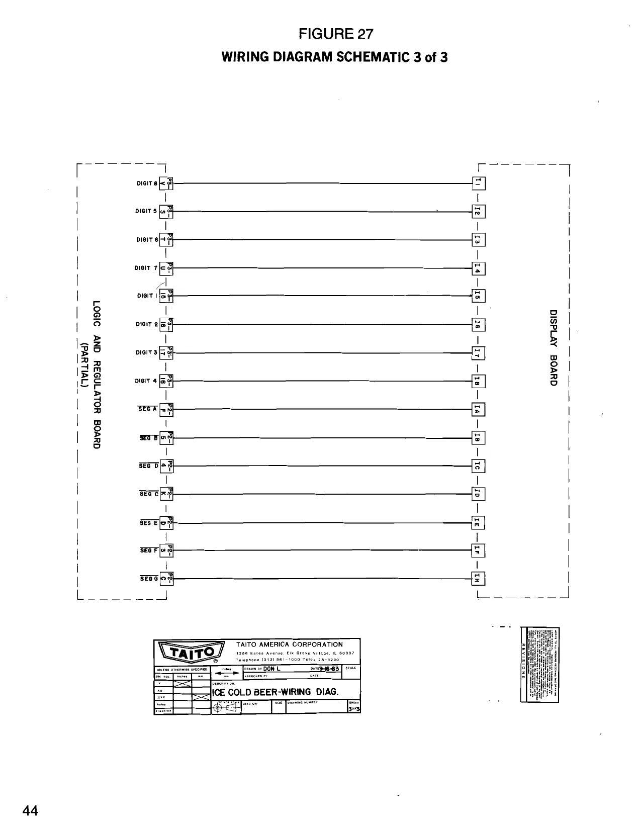
This page is a drawing, shown as the original scan.
EARTH ee hace
a Ka haa ICE COLD BEER-WIRING DIAG. Le Pl Ge] Bl Bel Gel Bel Bl ane PLAYFIELD (PARTIAL)
|_| I L. zy SOOHOOH
] be]
LOGIC __AND_REGULATOR BOARD (PARTIAL) —L THE a eee
a
PLAYFIELD (PARTIAL) COIN DOOR
LY + STetgereay 600 eae ticker com counreR COUNTER COUNTER (OPTIONAL) (OPTIONAL) 6v lav lav ms00t Wao woot FUORESCENT LAMP
POWER SUPPLY f] Gel G) 6 EES tle aw j Gl GG) &) fi Bl i B] &d Gi fd aecnnaal
- | [ | | wnt [oT | :
e = : joa _ J 4 rn 4 | == +
rom nsoronE 3] L woron fe F} THE ey eal come] BB ER aaron}
LoGic AND REGULATOR (PARTIAL) i
BOARD & a worrnon
WOPPER MT
TAITO AMERICA CORPORATION
BEER- WIRING DIAG.
Js J4 POWER SWITCH FLUORESCENT LAMP isTsJ2]'}
FL
- LOAD cuassis @ROUND
BLACK,
VARI lowe Tl
08-00128-001 POWER SUPPLY PCB ASSEMBLY
CHASSIS
TAITO AMERICA CORPORATION
POWER SUPPLY-ICE COLD BEER
8 Zz 6 5 4 3 2
- ALL RESISTORS 1/4 WATT UNLESS SPECIFIED.
- ALL CAPACITOR VALUES IN “uf” UNLESS SPEMFIED. _
DIP SWITCH
HEAT SINK TPS BYPASS B ‘AaVID 6080-38-2 (_)"5" TP,
F E34 ° wanna o1 v3 OT Leos one rus “aTOP ‘a70P a TAITO AMERICA CORPORATION
3 : =p ESSE se [> oPxn ern —T : A
IciRCUIT BOARD-ICE COLD BEER
oor fie
| 8 | ] | 7 | ! | 6 | 5 | | | 4 | | | 3 | | | 2 |
He
Qs TIPI2S ERO IDSEPBZ TC. H FB300 0 U3-N ri {> Lmoror cio! [- 470P 4T0Pp Boe a ced, = FIRQ IN4001
“FIR@ @9 TIPIZS
J3-12 ‘ood TD UMGTOR 70 470) I P ol P ag cual RESET CHB F CLK H cue IN4001
wy Fd a IF = Zz
- € w
FB33 3-10 —
ICON 5 27 BIR tone Ong Bleci G189!0 SOUND 1/0 = FILBIAS joa
| + | nc 24 teri | 1088 |
7407 zeut/iev ne-2eirsr2 Tose
| ney | Toes. | D |
TRFON- no—2] U9 toss (1-84)
BUFBIAS ci30] + 22ut/lev RIOe TIPI2Z0. c
SOUND 1 (cs) L
5 100 414uf/50V gk F-——rvv!0 TIPIZO é cise ALLCAPS ALL CAPS ‘470 470p
NOTES: _— TALL RESISTORS V4 WATT UNLESS OTHERWISE SPECIFIED. ci40 2.ALL CAPACITOR VALUES IN uf UNLESS TAITO AMERICA CORPORATION A OTHERWISE SPECIFIED, Bese toe Hie ance eminae 60807
MOTENBL ao — (qs) CIRCUIT AR D ~ BUFBIAS ICE COLD BEER [se 66241 -001 [yg
NOTES: | ALL RESISTORS AW UNLESS SPECIFIED. 2 ALL CAPACITOR VALUES IN “ut” UNLESS SPECIFIED.
HH
HH Hi
ay
F] HH 4 EY
g H A
a
a
Ors TSTROGE 6” Rez 120 aw T © cai
WARRANTY
TAITO AMERICA CORPORATION warrants that its printed circuit boards and parts are free from defects in material and workmanship under nomal use and service for a period of ninety (90) days from the date of shipment. Seller warrants that its monitors are free from defects in material and workmanship under normal use for a period of thirty (30) days from the date of shipment. The factory also warrants all socketed parts for a period of ninety (90) days when furnished with the game serial number. If the above products fail to conform to this Warranty Taito America Corporation has the option to repair, replace, or credit the Buyer’s account. The Buyer must notify Taito America Corporation in writing upon finding the defective product. Buyer must also return the defective product prepaid to Taito America Corporation’s factory located in Elk Grove Village, Illinois. If Taito America Corporation determines upon examining the returned product that damage was caused by accident, misuse, neglect, modification, or improper repair or testing, this Warranty will be void. Inno event will Taito America Corporation be held for loss of profits to Buyer.
TAITO AMERICA CORPORATION 1256 Estes Avenue, Elk Grove Village, IL 60007 Telephone (312) 981-1000 Telex 25-3290