Jack the Giant Killer
Jack the Giantkiller (set 1) (Hara Industries (Cinematronics license), 1982) · Manual · 37 pages · 14 sections · original scan
AWE the
GUANINE
OPERATION AND MAINTENANCE
MANUAL
CINEMATRONICS, INC. 1841 FRIENDSHIP DRIVE EL CAJON, CA 92020 (714) 562-7000
TELEX: CINEMAT ELCJ 697891
CALL TOLL FREE: (800) 854-2666
IN CALIFORNIA CALL: (714) 562-7000
SALES: 8-5 (PST) WEEKDAYS
SERVICE: 8-5 (PST) WEEKDAYS
JACK THE GIANTKILLER
GAME MANUAL
TABLE OF CONTENTS
FCC WARNING . . «© - e+ e+ e+ © 2 se eee
WARRANTY. . - 2 6 2 6 8 6 oe ee ew ee
CUSTOMER SERVICE PROCEDURES ..... .-
RECEIVING AND INSTALLING. .......
JACK THE GIANTKILLER - GAME DESCRIPTION.
OPTION SWITCH SETTINGS. ...- +--+...
ROUTINE MAINTENANCE AND SERVICE... -
WELLS-GARDNER COLOR MONITOR INFORMATION
PARTS LIST - COMPONENT P.C. BOARDS. . .
APPENDIX A - ASSEMBLY DRAWINGS AND SCHEMATICS
DATA POWER - POWER SUPPLY SCHEMATIC
UPPER P.C.B. COMPONENT LAYOUT DIAGRAM.
LOWER P.C.B. COMPONENT LAYOUT DIAGRAM.
GAME ELECTRONICS SCHEMATICS. .. . PAGE
1l
25-33
CINEMATRONICS, INC.
This equipment generates, uses, and can radiate radio frequency energy; and, if not installed and used in accordance with the Instruction's Manual, may cause interference to radio communication. As temporarily permitted by regulation, it has not been tested for compliance pursuant to Subpart J of Part 15 of FCC rules, which is designed to provide reasonable protection against such interference. Operation of this equipment in a residential area is likely to cause interference in which case the user at his own expense will be required to take whatever measures may be required to correct the interference.
WARRANTY
Cinematronics, Inc. warrants the goods to be free from defects in material and workmanship under normal use and service for a period of ninety (90) days from the date of shipment from factory. Cinematronics makes no representation or warranties concerning the goods whether express or implied by operation of law or otherwise, including those of merchantability or fitness for any particular purpose, or with respect of patent infringement, except as may be specifically made herein. Cinematronics limits its warranty obligations herein to the repair or replacement of such parts which have been returned to Cinematronics' plant at purchaser's expense and which examination shall disclose Cinematronics' satisfaction to have been so defective and to the shipment of such repaired or replacement parts to the purchaser F.0.B. the shipping
point.
This warranty does not apply to any Cinematronics' product which has been altered or repaired by unauthorized personnel or service facilities or any products which have had the unit serial number altered or removed.
Upon acceptance of the goods, the purchaser agrees to assume all liability for damages and/or bodily injury by the purchaser or any other person and to hold Cinematronics, Inc. harmless from liability or claims arising from the use of the goods by any person. Purchaser further agrees to indemnify Cinematronics, Inc. from any liability, claim, cause of action or litigation resulting from the use or misuse ofthe goods
by any person.
Parts-returned for warranty service must be packaged so that no damage is incurred during the shipment. Fu’l documentation and instructions must accompany returned parts. Parts must be shipped prepaid to: Cinematronics, Inc. 1841 Friendship Drive El Cajon, CA 92020
CUSTOMER SERVICE PROCEDURES FOR AUTHORIZED CINEMATRONICS' DISTRIBUTORS
It is the desire of Cinematronics, Inc. to provide efficient and courteous service should the need arise. We
have a fully staffed Customer Service Department and encourage you to call our toll-free number: (800) 854-2666 for technical assistance between the hours of 8:00 A.M. and 5:00 P.M., California time, Monday through Friday.
In order to provide the very best service possible, the following procedure for ordering or returning parts must be followed:
- All equipment ordered from Customer Service, whether in or out of Warranty, must be placed with a Distributor's purchase order, either by mail or verbally by telephone.
- Advance replacement items may be obtained only during the term of the Warranty and when such items are available, using the same procedure as when ordering parts. When ordering a PCB, please include with your order the game serial number and the number of the PCB you wish replaced.
- All items received as advance replacements will, after a period of thirty (30) days, become the property of the Distributor, with applicable charges applied in the event Customer Service has not received the defective item against which the advance replacement was made.
- The Distributor must call this facility for an RMA number prior to returning any item. Please be prepared to provide us with the game serial number and the PCB number when requesting an RMA.
- In all situations covered above, and in all other situations, the Warranty offered by Cinematronics, Inc. is applicable and should be fully understood.
- Parts returned for service must be packaged so that no damage is incurred during she shipment. Cartons without a prominently displayed RMA number will not be accepted. Full
documentation including game serial number, PCB number on outside of package, and reason for return must accompany parts. Ship prepared to: Cinematronics, Inc. Customer Service Department 1841 Friendship Drive El Cajon, CA 92020
(800) 854-2666 (714) 562-7000
RECEIVING AND INSTALLING
RECEIVING INSPECTION
Your game was shipped in ready-to-play condition. However, after removal of the shipping carton, a brief visual examination is suggested.
Naturally, you will want to make note of any physical damage to the game cabinet and its external components for freight claim purposes. Considering the quality of the shipping carton, any damage to the exterior would indicate possible interior damage as well.
The interior of the game should also undergo a brief examination for: loose mounting hardware (check to be sure that the major components are still securely mounted); disconnected or loose wires, cables or harnesses; electronic devices loose in their sockets; etc.
At this time the game serial number should be logged. Remember that the game serial number will be required if you need service from your distributor. Please complete the postage-free reply card and mail immediately.
ELECTRICAL REQUIREMENTS
Unless specified otherwise, your game was shipped to operate at 115 VAC, 50/60 Hz. .
A good earth ground is essential for the proper operation of this game or for that matter, any electronic device. Problems with instability and erratic operation of computer-type devices can usually be traced to an ineffective ground system. Therefore, plug the game into a properly wired three prong outlet. If a three prong to a two prong AC adaptor must be used, an alternate method of grounding the third prong must be used.
JACK THE GIANTKILLER
GAME PLAY
The game follows the story of Jack as he climbs the beanstalk to retrieve treasures from the giant's castle. The game has six different screens and twelve difficulty levels. The difficulty levels and the order of appearance of the screens are as follows:
DIFFICULTY LEVEL SCREENS
1, 5, 9 1, 4, 5 2, 6, 10 1, 2, 4, 5 3, 7, 11 1, 2, 3, 4, 5 4, 8, 12 1, 2, 3, 4, 5, 6
SCREEN 1 - JACK CLIMBING THE BEANSTALK
In this screen, Jack begins his ascent to the giant's castle. Jack must climb the beanstalk without falling off. Along the way, he can gather beans, which later can be used for protection against attacking enemies. This is the only time during the game when he can gather beans. Jack can either jump over or throw beans at his enemies. He also has the ability to jump from branch to branch on the beanstalk. During this scene, Jack must avoid the woodpecker, caterpillar, moth and flying bee.
SCENE 2 - JACK IN THE CLOUDS
After climbing the beanstalk, Jack must walk through the cloud pattern. One false step will cause Jack to tumble down to earth. Jack must avoid the lions and attacking birds as he makes his way to the castle's drawbridge. Jack may jump over the lions and birds or hit them with beans to destroy them. Once he has walked through the clouds, Jack must wait until the drawbridge is lowered to allow him to cross and enter the castle.
SCENE 3 - JACK ON THE STAIRWAY LEADING TO THE GIANT'S ROOM
Upon entering the castle, Jack finds himself on the stairway leading to the giant's room. Jack must run up the stairway leaping over the missing stones. Jack must also dodge the steps falling from above. In addition, Jack can jump over or throw beans at the mouse and cat running down the stairway.
SCENE 4 - JACK IN THE GIANT'S ROOM
Once Jack reaches the top of the stairs safely, he finds himself in the giant's room. A series of platforms and stairs lead up to the giant's table, where the singing harp, a bag of gold, the goose that lays the golden eggs, the princess and the sleeping giant are seen. Jack must jump from platform to platform and climb the stairs to reach the table. Flying magic lamps will attack Jack. Jack can either throw beans at the lamps or try to avoid them. The goose will move across the table laying golden eggs. If Jack can catch these eggs in the basket he is carrying, he scores extra points. Once Jack reaches the table, Jack must run to the object flashing (the harp, bag of gold, goose and then the princess) and rescue it.
SCENE 5 - JACK CLIMBING DOWN THE BEANSTALK
After rescuing the designated object, Jack must climb back down the beanstalk carrying the object under his arm and reach his cottage. In climbing down the beanstalk, Jack faces the same enemies he did while climbing the beanstalk. When Jack is climbing down the beanstalk with the princess, the giant will awake and begin to chase Jack down the beanstalk.
SCENE 6 - JACK CHOPPING DOWN THE BEANSTALK
Once Jack reaches the ground with the princess, he must fetch the axe lying near the beanstalk and begin chopping down the beanstalk. Jack must chop down the beanstalk before the giant reaches him.
When Jack successfully returns to his cottage with an object, a cartoon will appear. The objects to retrieve in order are the harp, the bag of gold, the goose and the princess. Once all of those objects have been retrieved, the scenes repeat themselves, only at a harder difficulty level.
DIFFICULTY LEVELS
All the adversaries that can appear in a screen will not be present for every difficulty level. The following table outlines the objects Jack will face in each screen and difficulty level. A dash indicates that a particular screen does not appear for the difficulty level.
DIFFICULTY LEVELS
SCREEN
| LEVELS: | 15,9 | 2,6,10 | 3,7,11 | 4,8,12 |
1 ‘Bee Woodpecker Woodpecker
Moth Moth Moth
Caterpillar Caterpillar Caterpillar Caterpillar
2 - None Lions Bizds
3 Falling Stairs Cat
= - Mouse Mouse
| 4 | None | None | None | Magic Lamps |
5 Bee Rocks Thrown Rocks Thrown Rocks Thrown Rocks Thrown
| by Giant | by Giant | by Giant | by Giant | |
| 6 | - | - | - | None |
If a player is in a particular screen for more than a predetermined amount of time, all possible adversaries will appear.
SCORING
50 Points for every bean picked 100 Points for hitting a woodpecker with a bean 100 Points for hitting a caterpillar with a bean 150 Points for hitting a moth with a bean 300 Points for hitting a bee with a bean 200 Points for hitting a bird with a bean 100 Points for hitting a lion with a bean 300 Points for hitting a cat with a bean 200 Points for hitting a mouse with a bean 500 Points for hitting a lamp with a bean 100 Points for catching a gold egg in the basket
Every time a screen is successfully completed, bonus points are awarded. The bonus points for each screen by difficulty level are shown in the table below. A dash indicates the screen does not appear in the difficulty level.
DIFFICULTY LEVELS
| SCREEN | 1,5,9 | 2,6,10 | 3,4,11 | 4,8,12 |
| 1 | 500 | 1000 | 1500 | 2000 |
| 2 | - | 1500 | 2000 | 2500 |
| 3 | = | > | 2500 | 3000 |
| 4 | 1000 | 2000 | 3000 | 3500 |
| 5 | 1500 | 2500 | 3500 | 4000 |
| 6 | - | - | - | None |
GAME FEATURES
Eight coinage settings. Either three or five "Jacks" per game.
Extra "Jack" every 10,000 points or one "Jack" at 10,000 points. Easy/hard difficulty switch, starts game at level one or level five.
Free play switch for demonstrations. Six different screens.
Twelve difficulty levels. Cartoons shown after each successful return to Jack's cottage. Complete hardware diagnostics accessed by dip switch.
OPTION SWITCH SETTINGS
Early model boards do not have Dip Switches ia Al
identified on board. Their location is as shown at right. Later model boards have OIP suitches labeled "SWI" and "SW2" next to SWITCH the Dip Switches themselves. Note that the locations of switches 1 and 2 are not identical on early and late model boards. (Early model PCBA: Has jumper wires on top board; later model boards do not)
DIP SWITCH NO.
PACTOR con [Tower DDT COIN OPERATE (CHUTE 1)
TIMES 1 NUMBER OF BEANS| TIMES 2
DIP SWITCH NO. ESCTORY Oo
ITABLE CABINET TYPE peace SYSTEM CHECK oo | | | PCB CHECK
ROUTINE MAINTENANCE & SERVICE
Because of the solid state electronic circuitry, this machine should require very little maintenance and only occasional adjustments. However, it is necessary to take measures to ensure this.
The volume control is located on the rear of the coin door and can be accessed by opening the coin door.
The video monitor has been properly adjusted before shipping. Occasionally minor adjustments are necessary. See monitor specifications and schematics for technical information. Adjustment controls for the monitor are located at the rear of the monitor.
This machine should be serviced only by a qualified technician.
Do not make any adjustments on this machine while the power is on.
For service information, contact:
CINEMATRONICS, INC.
1841 FRIENDSHIP DRIVE
EL CAJON, CA 92020
(714) 562-7000
POWER _SUPPLY
The computer board in this game operates most efficiently and reliably when the power,supply is set so that the voltage on the board is 5.0 volts, -0.1 volts. To check this, place a meter across 5 volts and ground at the edge connector. If necessary, adjust the screwdriver control on the power supply so the meter reads between 4.9 and 5.1 volts.
WELLS-GARDNER 19" COLOR MONITOR - MODEL 19K4675
WARNINGS
- Power Up Warning— An isolation transformer must be used between the AC supply and the AC piug of the monitor before servicing or testing is performed since the chassis and the heat sink are directly connected to one side of the AC line which could present a shock hazzard. Before servicing is performed, read ail the precautions labelled on the CRT and chassis.
- | X-RAY RADIATION WARNING NOTICE
- High Voltage— This monitor contains HIGH VOLTAGES derived from power supplies capable of delivering LETHAL quantities of energy. Do not attempt to service until all precautions necessary for working on HIGH VOLTAGE equipment have been observed.
- CRT Handling— Care must be taken not to bump or scratch the picture tube as this may cause the picture tube to implode resulting in personal injury. Shatter proof goggles must be worn when handling the CRT. High voltage must be completely discharged before handling. Do not handle the CRT by the neck. s. | PRODUCT SAFETY NOTICE
For replacement purposes, use the same type or specified type of wire and cable, assuring the positoning of the wires is followed (especially for H.V. and power supply circuits). Use of alternative wiring or positioning could result in damage to the monitor or in a shock or fire hazard.
PERFORMANCE AND OPERATING DATA
- Apply a suitable power source to the monitor through an isolation transformer.
- Apply a suitable signal source to the monitor PCB by means of P205.
- Set Up Controls. All controls are preset at the factory, but may be adjusted to suit program material. 1.0 Supply Voltage 108 VAC-132 VAC.
Frequency 50 Hz-60 Hz
3.0 Service Set-Up Controls INTERFACE PC BOARD POWER PC BOARD 3.8 Black Level Control, VR201
| 3.1 | Voltage Adjustment, VR501 (Set for 127V DC) | 3.9 | Horizontal Video Position Control, VR202 |
VERT/HORIZ PC BOARD NECK PC BOARD
3.2 Vertical Hold Control, VR301 3.10 Video Drive Controls, Red vO 2 3.5 Horizontal Hold Control, VR351 Blue VR 408
3.3 Vertical Size Control, VR302 reen
| 3.4 | Horizontal Oscillator Coil, L351 | S11 CAT Cut Off. Controfs, Red VEMGe | ||
| a6 | a yesh ional | 1604 | 3.12 Screen Control, VR406 | |
| .6 | Vertical | Raster | Position | Adjustment, |
6a 3.13 Focus Control, varee ssis
37 Baoan Position Adjustment, J608 3.14 Horizontal Width Coil, L702
SERVICE INSTRUCTIONS
1.0 +127V ADJUSTMENT (See Fig. 1) The + 127V adj. control (VA501) is adjusted at the factory. However, if readjustment should be required, proceed as follows. 1.1. Operate monitor for at least 15 minutes at 120V AC line. 1.2 Connect Positive lead of V.T.V.M. to blue lead of TRS502 negative lead to chassis ground. Adjust VR501 to obtain + 127V reading. After adjustment VR501 must be locked with a sealing varnish. 2.0 BLACK LEVEL CONTROL ADJUSTMENT This control has been set at the factory and should not need further attention, however, when the game is connected a slight adjustment of VR201 may be necessary to obtain the proper black level (the black portion of the picture just extinguished). 3.0 VERTICAL SIZE (HEIGHT) The vertical height control is a screw-driver adjustment. Location of this control is shown in Fig. 2. This control must be adjusted slowly, if necessary, until the picture or test pattern attains the correct vertical proportions.
4.0 CIRCUIT PROTECTION A3.0A pigtail fuse, mounted on the Main Board has been provided to protect the Power Output Circuit.
5.0 FOCUS Adjust the Focus control (VR702), located on the HV unit(T701), for maximum over-all definition and fine picture detail. 6.0 HORIZONTAL OSC. ALIGNMENT (See Fig. 2) A warm-up period of at least five minutes should be allowed before alignment is carried out. With the monitor being driven from the game signal, set VA351 to its mechanical center and short the lower end of R328 (TP32) to ground. Adjust L351 until picture stops sliding horizontally. Remove the short. 7.0 HORIZONTAL VIDEO POSITION If the video is off center on the raster some compensation can be made by adjusting this control.
8.0 VERTICAL RASTER POSITION ADJUSTMENT If the video is off center vertically, (short dimension of picture tube) some compensation can be made by moving J604 to either No.1 or No. 3 of P604. Position No. 1 moves raster up and position No.3 moves raster down. 1.3 1.4 9.0 HORIZONTAL RASTER POSITION ADJUSTMENT If the video is off center horizontally (long dimension of picture tube) some compensation can be made by moving J608 to either No. 1 or No.3 of P608. Position No. 1 moves raster to the left and position No. 3 moves raster to the right.
VR5O1 +8 Ady n
TREO2 Emitter
(eee son
TR352
FIGURE 2 VERT/JHORIZ. BOARD
P.C. BOARD LAYOUT
P.C. BOARD LAYOUT
FIGURE 16. INTERFACE BOARD (P317 AND P318)
FIGURE 12. MAIN P.C. BOARD P.C. BOARD LAYOUT
REAR CHASSIS CONTROLS
HORIZONTAL OSC. COIL: (L351)
Focus
VERTICAL, RASTER POSITION
HORIZONTAL WIOTH COIL,
ER END OF R328)
VERTICAL, = HORIZONTAL = HOLD (CA HORIZONTAL = HOLD VIDEO Lary POSITION POSITION
FIGURE 17
WGEC SERIES 4800 69X1090-100
WELLS-GARDNER COLOR MONITOR
ADJUSTMENT CONTROLS LOCATION
12.
13.
14.
15.
16.
17.
18.
19.
20.
21.
22.
23.
24.
25.
26.
27.
28.
29.
30.
31. 74LS00
74LS02
74LS04
7404
74LS08
74LS10
74LS20
74LS30
74LS32
7438
74LS74
74LS86
74LS90
74LS107
74LS138
74LS139
74LS154
74LS155
74LS157
74LS161
74LS175
74LS194
74LS240
74LS244
74LS245
74LS273
74LS283
74LS378
74LS393
Z80A JACK THE GIANTKILLER
PARTS LIST
DESCRIPTION
Ic
Ic
Ic
Ic
Ic
Ic
Ic
Ic
Ic
Ic
Ic
Ic
Ic
Ic
Ic
Ic
Ic
Ic
Ic
Ic
Ic
Ic
Ic
Ic
Ic
Ic
Ic
Ic
Ic
CPU (CPU Section)
CPU (Sound Section) USAGE
PE wWUNnN WOE DARE AAKH YP NNP RP HOH UHHYENYWNUYY A
NO.
32.
33.
34.
35.
36.
37.
38.
39.
40.
41.
42.
43.
44.
45.
46.
47.
48.
49.
50.
51.
52.
53.
54.
55.
56.
57.
58.
59.
60.
61. 2732
M58725P
2114-2
82816
748189
AY~-3-8910
Upd 1510
MB 3713
MC 14066
2732
280945
181588
18.000
0.22uf 35v
22uf l6év
47uf lév
1o0uf lév “loouf 25v
470uf l6v
100pf S0v 0.0luf 25v
0.047uf 25v
Q.luf l2v
100 ohm § watt 220 ohm % watt 330 ohm 4 watt 470 ohm } watt 1K ohm } watt 4.7K ohm } watt DESCRIPTION
ROM IC
RAM IC
RAM IC
RAM IC
RAM IC
Ic (LSI)
Ic (Custom LSI)
(Linear IC)
(Linear IC)
(cmos IC)
E PROM
Transistor
Diode
MHz Crystal Tantalum Capacitor Electrolytic Capacitor Electrolytic Capacitor Electrolytic Capacitor Electrolytic Capacitor Electrolytic Capacitor Ceramic Capacitor Ceramic Capacitor Ceramic Capacitor Ceramic Capacitor
Resistor
Resistor
Resistor
Resistor
Resistor
Resistor USAGE
w a RO
Br rFP FPN RPP RENE NN EP Pe ei
ST °
| NO. | DESCRIPTION | USAGE | |
| 62. | 5.6K ohm } watt | Resistor | 1 |
| 63. | 10K ohm } watt | Resistor | 1 |
| 64. | 220 ohm } watt | Upright Resistor | 24 |
| 65. | 220 ohm | Potentiometer | 1 |
| 66. | 1028 | DIP Resistor Pak | 4 |
| 67. | 4728 | DIP Resistor Pak | 2 |
| 68. | 1038 | DIP Resistor Pak | 2 |
| 69. | DIP Switch, 8 Position | 2 | |
| 70. . | 40 Pin IC Socket | 1 | |
| 71 | 24 Pin IC Socket | 18 | |
| 72. | . | 18 Pin IC Socket | 1 |
| 73. | 60 Pin Male Connector | 1 | |
| 74. | 60 Pin Female Connector | 2 | |
| 75. | Printed Circuit Board #1 | 1 | |
| 76. | Printed Circuit Board #2 | 1 |
APPENDIX A
Assembly Drawings Schematics
and
Wiring Diagrams
se eseee ewe Hy p53 Jace [>
o mPUT SELECTION vor st se joow uF OB .15v caw uP 2000 uP DOWN 230V nown one
15 VAC output ® Jl ® NS WAS output ZALL 1% RESISTORS ARE QW FRESISTOR WLUES ARE mH OHMS, t 514,'4W sores waste onsemmen perce
POWER SUPPLY
@ “T 7 T 6 a ns aa « 3 | 2 T 1
JACK THE GIANTKILLER UPPER PRINTED CIRCUIT BOARD
COMPONENT LAYOUT DIAGRAM
JACK THE GIANTKILLER
LOWER PRINTED CIRCUIT BOARD
COMPONENT LAYOUT DIAGRAM
#2) ma a
Home a
Ws] L|
+ LI er te LIU uu
L T GAME-28_ MAQE IN JAPAN
oy t yt Uy
e L IT iL ipa
pp ”
&
“LU nin
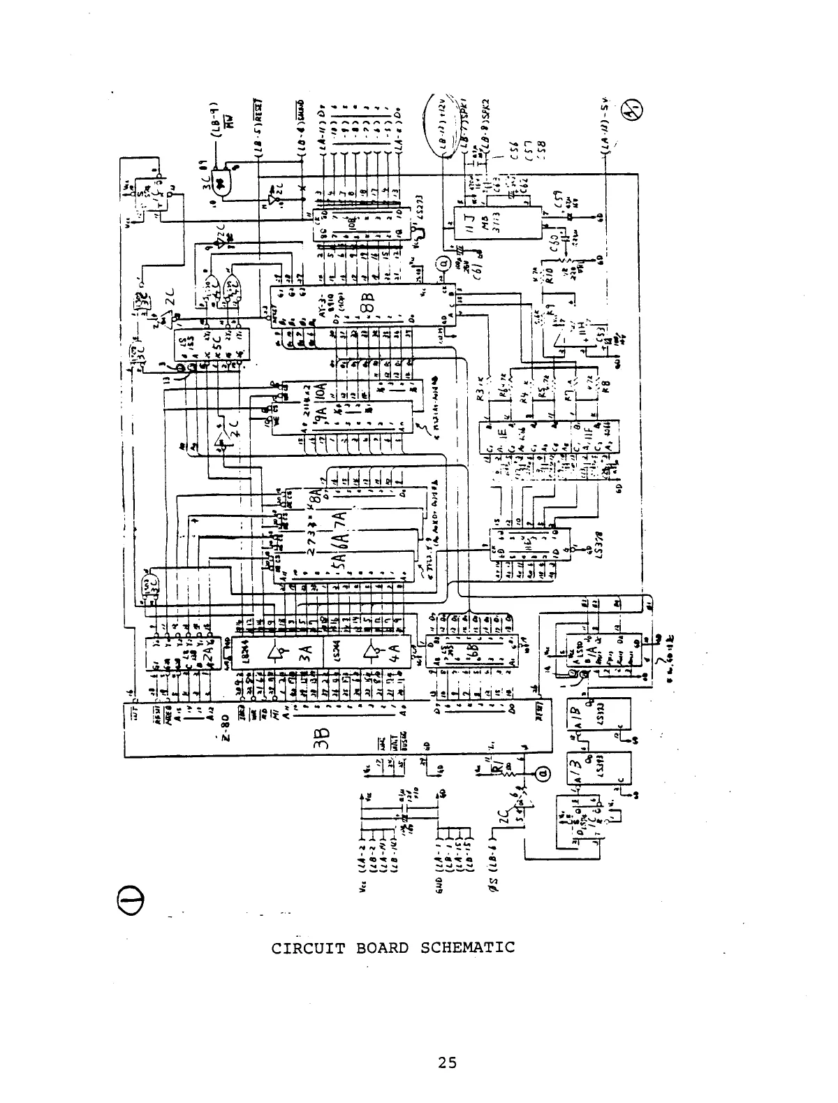
This page is a drawing, shown as the original scan.
CIRCUIT BOARD SCHEMATIC =5¥ (FAA 6 SPR AE — Ob Spi 5Pk2 (18:4 {Ub Hispea 9S GAS Abb) ws it vane Pir wy Ae Ou 6 0, /
Sane ca Me
Se w rtd Gyms a V8) 3MHy a8 a) iNT Al —P ai wea aT Sb.ro,; nw n e |____.. —a- sys
ANTCLE (9: 4y— asd &-
CIRCUIT BOARD SCHEMATIC
RED (8b}————{en GREEN (39-771 BLUE (8 8y>—————4 CHPSYNT (281-1
CIRCUIT BOARD SCHEMATIC
© verse —- Tay wy — _— avai on ——________ — We re PD ~ fe 1 5 A _—- sepa
i <i?
-CIRCUIT BOARD SCHEMATIC
@ VEO-vE2 €) vPO- Fs B® Ko-Wea
eusnTeS eat
- -CIRCUIT BOARD SCHEMATIC
Peniesaen sy
“CIRCUIT BOARD SCHEMATIC eLece «ED
CIRCUIT BOARD SCHEMATIC
By 40g. 104 19-0 By 306-*
CIRCUIT BOARD SCHEMATIC
This page carries no recoverable text. It is a drawing or a photograph. See the original scan.