Mr Do Castle
Mr. Do's Castle (set 1) (Universal, 1983) · Manual · 19 pages · 23 sections · original scan
This page carries no recoverable text. It is a drawing or a photograph. See the original scan.
WARNING:
THIS EQUIPMENT GENERATES AND USES RADIO FREQUENCY ENERGY
AND IF NOT INSTALLED AND USED PROPERLY, I.E., IN STRICT ACCORDANCE WITH THE INSTRUCTIONS MANUAL, MAY CAUSE HARMFUL INTERFERENCE TO RADIO COMMUNICATIONS. IT HAS BEEN TESTED
AND FOUND TO COMPLY WITH THE LIMITS FOR A CLASS A COMPUTING
DEVICE PURSUANT TO SUBPART J OF PART 15 OF FCC RULES, WHICH
ARE DESIGNED TO PROVIDE REASONABLE PROTECTION AGAINST SUCH
INTERFERENCE WHEN OPERATED IN A COMMERCIAL ENVIRONMENT.
OPERATION OF THIS EQUIPMENT IN A RESIDENTIAL AREA IS LIKELY
TO CAUSE INTERFERENCE IN WHICH CASE THE USER AT HIS OWN
EXPENSE WILL BE REQUIRED TO TAKE WHATEVER MEASURES MAY
BE REQUIRED TO CORRECT THE INTERFERENCE.
UNIVERSAL
Thank you for your purchase of UNIVERSAL’S MR. DO'S CASTLE CONVERSION KIT.® Before attempting installation make certain that your conversion kit is complete.
Your kit includes:
- Mr. Do's Castle P.C.B. (contained in a R.F. shield)
- Audio Amplifier P.C.B.
- License Sticker
- Main Harness Assembly
- 4-Way Joystick
- Push Buttons (complete with housing)
- 24” X 9" Clear Control Panel Plexi Glass
- set of Control Panel Decals
- Policarbonate Control Panel Overlay
- Mr. Do’s Castle Marquis Plexi
- set of Mr. Do's Castle Side Decals AC-TONMoOOD>Y
CONTENTS
I. Howto play 2.0.6... cece eee eee eee eee e eee eenenene 1 Il. Various optional settings ......... 2... eee cere ence en eneeees Ill. How to conduct self-testing 2.0... 0... eee eee eee IV. Main circuit board IC location and parts list V. Wiring diagram (Connector) .......... VI. Main circuit board schematic diagram VIL. Block diagram 2.6... eee cece e eee eneeenennennee
REFERENCE DRAWINGS
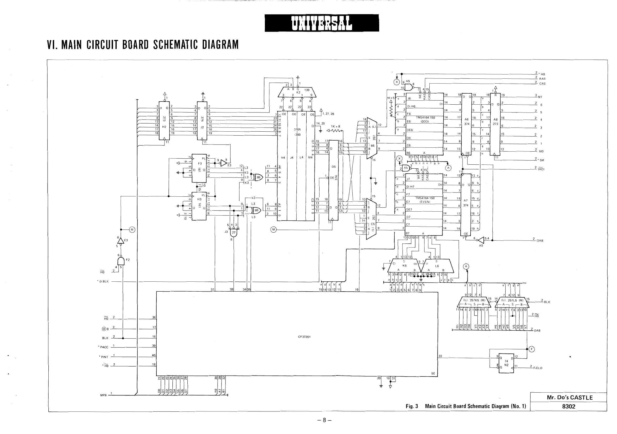
Fig.1 Main Circuit Board IC Location. . Fig. 2 Wiring Diagram (Connector)... 1.0.0... eee eee ee eee ee eeeeceeaes Fig.3 | Main Circuit Board Schematic Diagram (No. 1) Fig.4 Main Circuit Board Schematic Diagram (No. 2) Fig.5 Main Circuit Board Schematic Diagram (No. 3) Fig.6 Main Circuit Board Schematic Diagram (No.4) ... . Fig. 7 Block Diagram 2... 1... ec cece eter e cent eeeuenees 11
SPECIFICATIONS
TABLE TYPE UPRIGHT TYPE
564 m/m (D) AC100V/115V/230V | 800 m/m (D) AC100V/115V230V 863 m/m (W) 50/60Hz 640 m/m (W) 50/60Hz 570 — 680 m/m (H) 140W (18'") 1750 m/m (H) 180W (20"’)
Y 95-2447 Y 95-1653
UNIVERSA
|.HOW TO PLAY
1.
2.
10.
11.
12. Operate Mr. Do! by means of the lever.
After dropping a block by use of the hammer, skillfully drop the unicorn into the hole. Then drop the block onto the unicorn and you can exterminate it.
You can also exterminate the unicorn by dropping a block onto it while it is walking.
You can hit and knock over a unicorn by use of the hammer in scenes 1 and 2.
Make good use of the skull blocks, and you can wipe out several unicorn at a time. When dropping both skull blocks, the blocks between them will also drop at the same time.
Only Mr. Do! can remove the ladder.
If Mr. Do! has been trapped between two unicorns on the blocks, you can help him escape by dropping a block with the hammer.
When three of the key blocks have been dropped, the door on the top level will open and a shield will appear. If you wipe it out the unicorns will change to EXTRA.
You can exterminate EXTRA by hammering it or dropping Mr. Do! on it. When it has been wiped out, a flag will be run up on the pole.
Another Mr. Do! will appear if you succeed in running up five flags, EX T R A on the pole.
The last unicorn in scenes 1 and 2, will change and split into the blue unicorns after 20 seconds — after a further 25 seconds, the blue unicorns will split into double unicorns, and then after another 5 seconds these will become eight — there will be no further increase.
Red unicorns will become green if Mr. Do! hits them four times with the hammer, and green unicorns will become blue when he hits them once with it.
—— ASSAULTING SCORE
When walking When in the hole
500~ 2,500 pts 20 pts
1,000~ 1,500~ 5,000 pts 8,000 pts
1,500~ fag) ------- 500~ 7,500 pts a 2,500 pts
e Dip Switch A UNIVERSA
I]. VARIOUS OPTIONAL SETTINGS
DESCRIPTIONS OF DIP SWITCHES
- Number of Mr. Do! Given (SW1, 2)
- Difficulty of the Games (SW7, 8)
| No. of Mr. Dot | swi | sw2 | Difficulty | sw7 |
| 3 | OFF | OFF | 1 (Beginner) | OFF |
| 4 | OFF | ON | 2 | OFF |
| 5 | ON | OFF | 3 | ON |
| 2 | ON | ON | 4 (Advanced) | ON |
- Game Style (SW3) Style Table Upright
- Difficulty of EXTRA (SW4) © Positions of Dip Switches
Difficulty SWw4 Easy OFF
Difficult ON
- SW5 is not used.
- Automatic Renewal of Screen (SW6) Automatic renewal SW6
Made OFF
Not made ON
© Dip Switch B (Coin & Credit) MAIN CIRCUIT BOARD
Dip swA Dip Sw B
Left-side chute Right-side chute Coin | Creat Sai | _sw2 | swa | swa | swe | swe | sw? | swe |
| 1 | 1 | OFF | OFF | OFF | OFF | OFF | OFF | OFF | OFF |
| 1 | 2 | OFF | OFF | OFF | ON | OFF | OFF | OFF | ON |
| 1 | 3 | OFF | OFF | ON | OFF OFF | OFF | ON | OFF | |
| 1 | 4 | OFF | OFF | ON | ON | OFF | OFF | ON | ON |
| 1 | 5 | OFF | ON | OFF | OFF | OFF | ON | OFF | OFF |
| 2 | 1 | OFF | ON | OFF | ON | OFF | ON | OFF | ON |
| 2 | 3 | OFF | ON | ON | OFF | OFF | ON | ON | OFF |
| 3 | 1 | OFF | ON | ON | ON | OFF | ON | ON | ON |
| 3 | a | ON | OFF | OFF | OFF | ON | OFF | OFF | OFF |
| 4 | 1 | ON | OFF | OFF | ON | ON | OFF | OFF | ON |
| 1 | 1 | ON | OFF | ON | OFF | ON | OFF | ON | OFF |
1 1 | on | orF | on | ON | ON | OFF | on | ON
| 1 | 1 | ON | ON | OFF | OFF | ON | ON | OFF | OFF |
| 1 | 1 | ON | ON | OFF | ON | ON | ON | OFF | ON |
| 1 | i | ON | ON | ON | OFF | ON | ON | ON | OFF |
| Free play | ON | ON | ON | ON | ON | ON | ON | ON |
Standard and Custom Price Settings
The game price set by’a combination of dip SWs is displayed on the monitor when coin credit is 0.
a)
b) When the settings for right and left chutes are the same, “1 coin — 1 credit’, ‘2 coins
- 3 credits’, etc. are displayed.
When the settings for right and left chutes are provided differently, their respective contents can be displayed.
[Self-Testing Procedure]
Turn power ON while pressing the push-button or either the 1st or the 2nd player side, and self-test:
UNIVERSAL
II]. HOW TO CONDUCT SELF-TESTING
- This machine has a self-testor which locates any abnormalities with the machine should they occur.
ing will follow automatically.
[Self-Testing Items]
- RAM Test: When normal When abnormal
- ROM Test: When normal When abnormal
- Sound OFF: “SOUND OFF” will appear on the screen, and the sound that has been made to that time will stop, “RAM OK” will appear on the screen, and the test will proceed to the next step. “RAM oO "will appear, and the test will be suspended.
‘Abnormal RAM No.
“ROM OK” will appear on the screen, and the test will proceed to the next step. “ROM [] . (JL “ will appear, and the test will be suspended.
Vabnormal ROM data
Abnormal ROM No.
then, the test will proceed to the next step. The machine is out of order if the sound does not stop or the test does not proceed to the next step. .
- Switch Test: Switch names are displayed on the left side of the screen, while input conditions will be displayed on the right side. When the switch is ON, “0” is displayed for input, and when it is OFF, ‘1" is displayed. Conduct test while turning each switch ON-OFF — the test will advance to the next step after a minute.
Switch name Input condition Switch name Input condition 2P DOWN COIN LEFT LEFT COIN RIGHT UP, RIGHT 1P_ OOWN LEFT UP, RIGHT 2P START NOT USED 2P JUMP, FIRE 1P START NOT USED 1P JUMP FIRE NOT USED NOT USED Sy re gs er
“0” will appear when pushing the pushbutton on the 1st player's side.
Dip switch A
7 B
- TV Monitor Test: Cross hatch pattern will appear on the entire screen. Monitor adjustment can be done by means of the pattern.
© Self-testing will stop at this point. Turn ON power again when you want to resume game or execute self-test again.
- In case you have found any abnormality as a result of the self-test, contact the dealer who sold the machine to you.
UNIVERSAL
IV. MAIN CIRCUIT BOARD IC LOCATION AND PARTS LIST
UNIVERSAL
[1] Integrated Circuit [2] Capacitors Item No. Description Description
| 74LS OON | 0.1uF 16V | 22 | Ceramic Capacitor | ||
| 74LS 01 | 1 | 0.1uF25V | 3 | " | |
| 74LS 04 | 4 | o.oomrav | 4 | | “ | ||
| 74LS 08 | 1 | " | 400PF50V | 3 | " |
| 74LS 20 | 2 | |” | 100PF50V | 1 | 7 |
| 74LS 27 | 1 | 4" | SOPF50V | 1 | " |
| 74LS 32 | 1 | 2 | 47uF 16V | 1 | " |
| 74LS 74 | 5 | |” | 10uF 16V | 2 | “ |
| 74LS 86 | 7 | |" | 22uF 16V | 1 | ” |
| 74LS138 | 3 | |” | 47uF 16V | 1 | * |
| [7418139 | 3 | |" | 470uF6.3V | 1 | " |
| 74LS157 | 6 | |” | 0.22uF 16V | 1 | ES Capacitor |
| 74LS161 | 3 | |” | 1000uF 16V | 1 | ” |
| 74LS244 | 3 | |" | |||
| JAtS246 | u | “ | [3] Registors | ||
| TALS257 | 4 | “ | Rating | Q'ty | Description |
| 74LS273 | 6 | |” | : | ||
| 7418283 | 3 | 7 | = | : | Carbon oct | |
| 74LS373 | 1 | Z | 7000 | 7 | = |
| 74LS374 | 4 | |" | |||
| 74ALSO4N | 1 | ” | a | s | - |
| 74ALS08 | 1 | " | 3308 | 4 | _ |
| 3902 | 3 | " | |||
| 748374N | 1 | " | Bi0n | ri | x |
| Z80A | 3 | NMOS CPU (4MHz) | a0 | 2 | 7 | |
| 2764-300 | 8 | NMOS 64K bits EP ROM | Tay | 3 | = |
{Access 300nsec) + ~
| 27128-300 | 2 | NMOS 128K bits ROM | 15K | 4 | : |
| (Access 300 nsec) | 2KQ | u | ‘ | |
| N82S147 | 2 | 4096 bits Fuse ROM | 22K | u | ” |
| TMS4164.200 | 16 | 64K DRAM | 5.1KQ | u | ” | |
| MB8128-150 | 5 | NMOS 16K bits Static RAM | 1002 |
(Access 150nsec) 1202
| MB8128-100 | 1 | NMOS 16K bits Static RAM | 512. |
(Access 100nsec) 330 x 8
| CF37201N | 1 | Custom Function | 1Kx8 |
| NE556 | 1__| | Timer | 10K x8 |
| MB3730 | 1 | Audio Amplifier | 1KQB |
SN76489AN 4 | Programable Sound Generator TMS1025N2cL_| 2 | CMOS
| HD46505SP | 1 | crTc | — |
ToD1 4 Diode Description
| UA7805 | 1_ | Regulator | = Serene |
This drawing provides standard information. Universal reserves the right to change without notice. 4.000MHz IC Socket
Fig. 2. Wiring Diagram (Connector) DooR sw Fuse Gr w do oo ee Bo So rete [x
nerd main sw BkIGND)
POWER SUPPLY
speaker { 8k 1 y COIN SW IL} Ra_J i+12V)
NC. bs
N.O. ao:
COMMON 5
>BO:
COIN SW(R)
EI
N.C NO. Bk
common — Gite (=
UPPER SW
RIGHT sw
SOWN SW
FT SW
Ra Ga Bu Bk oP
COIN 23d a
COUNTER LeeT—St o S74 b Br Br Ww
RIGHT. a TI * = ° 2 bu TV MONITOR
Pk V. WIRING DIAGRAM (CONNECTOR) UNIVERSAL
MR. DO’S CASTLE HARNESS PIN ASSIGNMENT
SOLDER SIDE
USE COLOR
2nd PLAYER Bik, GND r--- COIN SW SLAM SW GND
AUDIO AMP BOARD
/—) —_7
Bk acy
Or/ Pur
Lio won
sLaM sw Gn.
2nd PLAYER UP
FOR 2nd PLAYER RIGHT 8rn.
C: TABLE
2nd PLAYER DOWN Yel.
2nd PLAYER LEFT = Pur.
2 PLAYERS SELECT Grn.
VIDEO RED Red
TO VIDEO GREEN Grn. MONITOR VIDEO BLUE Blue composit SYNC Wht.
GND Blk.
CONNECTION FOR USE WITH COIN METER
R COIN SW
GND COIN COUNTER GIN #8) T ! CONNECT EITHER PIN #24 OR #25 +5v QIN #4)
L COIN SW ak. | a2 | Bik.
Loaf iepe | es COMPONENT SIDE
COLOR
Bik. GND (TO POWER SUPPLY)
GND (1st PLAYER & SELECT SW)
Ora. +5v (TO POWER SUPPLY)
Ora, +6v (COIN COUNTER)
Ora. VERT. SYNC Brn, HOR, SYNC )r0 m
+12v (TO POWER SUPPLY)
1st PLAYER UP
Brn, 1st PLAYER RIGHT uber
JOYSTICK
Yel. 1st PLAYER DOWN
Pur. 1st PLAYER LEFT
Ora. 1st PLAYER SELECT
Red 1st PLAYER THROW
Red 2nd PLAYER THROW (FOR C- TABLE)
Yel. LEFT COIN SW/COUNTER
Brn. RIGHT COIN SW/COUNTER
CONNECTION FOR USE WITHOUT COIN METER
NC
EITHER PIN #24 OR #25 +5v (PIN# 4)
GND (PIN#B)
O
oo LE Jt +6 MODIFICATION FOR POSITIVE HORIZONTAL AND VERTICAL OUTPUT
472 %W
+VERT SYNC
+ VERT SYNC
Fe FA g fe}
+HOR SYNC
- BE SURE TO REMOVE COMP SYNC LINE WHEN INSTALLING THE POSITIVE INDEPENDANT SYNC LINES.
This page is a drawing, shown as the original scan.
This page reads as a drawing: its text was drawn rather than typeset, and comes out in fragments. See the original scan.
This page reads as a drawing: its text was drawn rather than typeset, and comes out in fragments. See the original scan.
UNIVERSAL
VII. BLOCK DIAGRAM
Z| i 2D--{_Door sw. }+{ Main sw. }+{ Transformer -———_——___. TV
| Fa | g | | | Monitor |
| g | ;o/ 8] | [Pp Ss of | |
| pS | al8! | {__Power Supply -— | J Video Signal |
lola. ee -—
| - | | fal | Start SW. |
| 8 ls | lS | ——————_+ Main |
| ® | = I | | Contro} Lever | Board |
| | | oo | Speaker |
L Fire SW. j = + oO Coin SW. ‘ 2) Coin Counter
| ¢ | 1 [weevar 3 | ll i | ||
| 3 | z | Ss | . | . |
| Ta | t] of o | oe] | Fig. 7 Black Diagram | |
| z| 3 | £ | — | - — |
& ——s & S o >: ier 2 ° ee ral l 2
| qo). 4) | rt | & |
| 3
| ¥S ¥S 5S & | ° | - | = | |
| 2g ag 2s 2 | 2 | ww | . ‘ |
| 2 | = | So |
Z if 5 al
© x x > iz
GNo se (4)
CASTLE
COPYRIGHT INFRINGEMENT POLICY
Universal USA Inc., holds the sole proprietary interest for the manufacture of the Mr. Do’s Castle video game, and has registered a copyright and trademark with the United States Copyright Office.
Due to Mr. Do’s Castle’s excellent earnings report, there may be those interested in illegally reproducing this game.
LET THERE BE NO MISTAKE! Universal USA Inc., will protect it’s proprietary rights by taking any and all legal action necessary against any person or company that manufactures. sells, distributes, and/or operates any game which violates these exclusive rights of the Mr. Do's Castle video game. Any violation whatsoever will be prosecuted to the fullest extent of the law.
Authenticity of any Mr. Do’s Castle game can be verified by calling 1-(800) 538-7538 during regular business hours.
L
Universal U.S.A., Inc. 3250 Victor Street (408) 727-4591 Santa Clara, CA95050 TELEX: 172247
Head Office: Universal Co., Ltd. 4-7-7, Nihonbashi Horidome-cho, Chuo-ku, Tokyo 103, Japan Phone: 03-661-6004, 6005 Cable: UNMANIF ACT Telex: J27348 (UNICO)
Universal U.S.A. inc. 3250 Victor Street, Santa Clara, California 95050, U.S.A. Phone: 408-727-4591-5 Telex: 172247 (UNI USA SNTA) Main Line of Business: Development, manufacture, sales, and export & import ot amusement machines
European Office 81 Tottenham Court Road, London W1A 1EY Phone: 01-631-1713 Telex: 892989. ELCOIN