Tempest DP-190-2nd-01B
Tempest (rev 3, Revised Hardware) (Atari, 1980) · Drawing Package · 1 pages · original scan
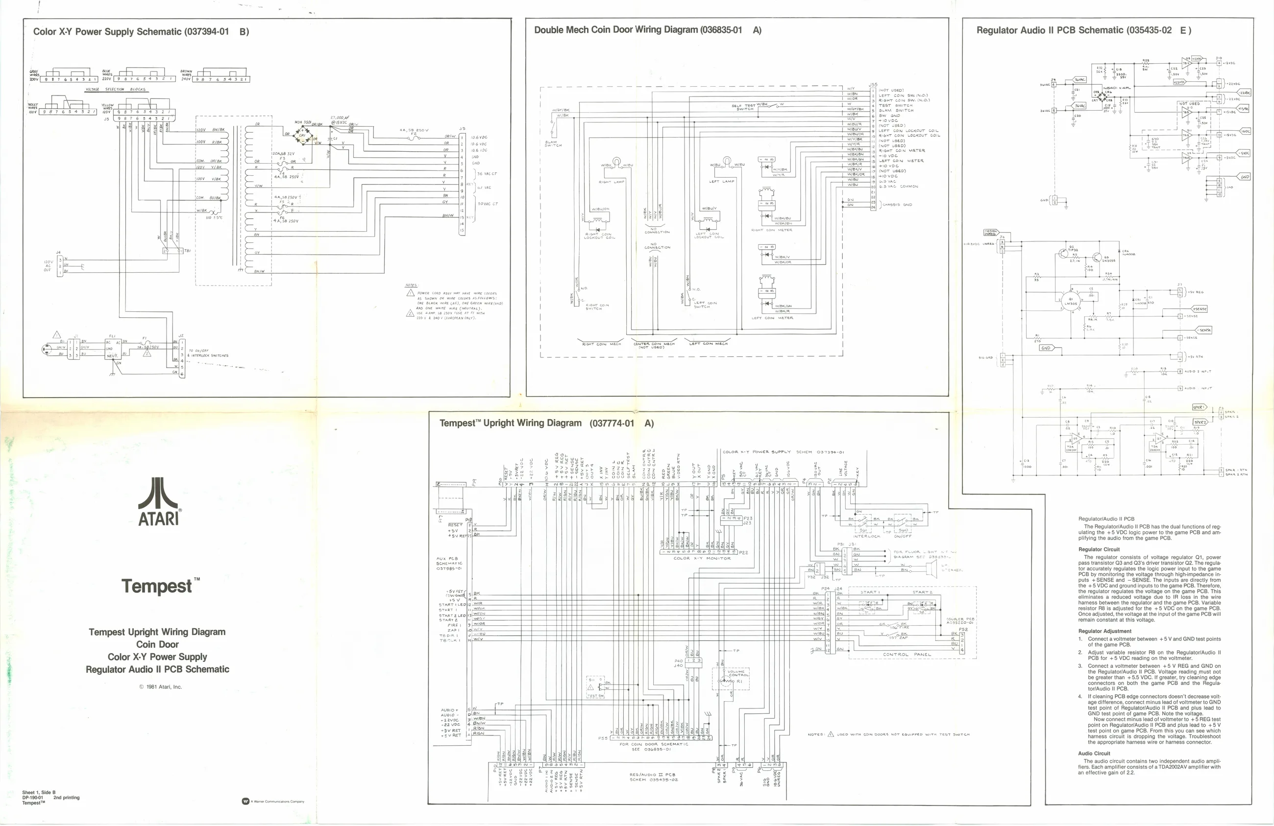
Color XY Power Supply Schematic (037394-01 B)
cA Soot Boe A “ears C11 fal T] Mov[ee 7 ses]
ey cher | CHE, & aif H ii Double Mech Coin Door Wiring Diagram (036835-01 A) Regulator Audio Il PCB Schematic (035435-02 E)
ATARI
Tempest”
Tempest Upright Wiring Diagram Coin Door Color X-Y Power Supply Regulator Audio Il PCB Schematic
© 1981 Atari, inc.
Sheet 1, Side Bps0ot Sn printing owe Ome comnncnon convey yaa 0.6 voe
{or me \ \ sovac cr i 7 4 eee Jemsers ono
I
| a fons: It a 3 LA Power cone assy ser nae wine caters al\ sl\°
° | i
: wre EGE ere’
i as
Tempest™ Upright Wiring Diagram (037774-01 A)
int CUTE ilo vee. | suoe of your A 2| tsvaer axe] ein
- Butt) com evra,
real pag) “22 oe —wiest9) «2 voe
Regulator/Audio II POB p23 The Rogulator/Audio Il PCB has the dual functions of reg: lating the +5 VDC logic power to the game PCB and amplitying the audio from the game PCB, Regulator Circuit lator consists of voltage regulator Q1, power regi pass transistor Q3 and Q3's driver transistor 2. The regula tor accurately regulates the logic power input to the game PCB by monitoring the voltage through high-impedance inputs +SENSE and ~SENSE. The inputs are directly trom the + 5 VOC and ground inputs othe game PCB. Therefore the volt
feslstor Ro is adjusted forthe. +3 VOC onthe game PCs
(Once adjusted, the voltage atthe input of the game PCB will
remain constant at this voltage. ite) Regulator Adjustment Pee H 4. Connect vometer between +5 Vand GND test points of the game PCB.
mores: A\ vaeo wirm com
nee/avoio Pee A Seren csoa2s-o2, Fy i 2. Adjust variable resistor RB on the Regulator/Audio tI 4 PCB for +5 VDC reading on the voltmeter.
- Connect a voltmeter between +5 V REG and GND on the Regulator/Audio II PCB. Volt be greater than +5. VDC. I grate ty cleaning edge connectors on both the game PCB and the Regula. toriAudio Il PCB. ‘4. If cleaning PCB edge connectors doesn't decrease volt: age difference, connect minus lead of voltmeter to GND. test point of Regulator/Audio Il PCB and plus lead to GND test point of game PCB. Note the voltage.
age difference, connect minus lead of voltmeter to GND Now connect minus lead of voltmeter to +5 REG test the appropriate hares wire or harness connector fiers. Each amplifier consists of a TDA2002AV amplifier with
point on Regulator/Audio ll PCB and plus lead to +5 V test point on game PCB. From this you can see which hhamess circuit is dropping the voltage. Troubleshoot the appropriate hares wire or harness connector. CONTROL PANEL
Audio Circuit ‘The audio circuit contains two independent audio ampli-
an eifective gain of 2.2.