Asteroids DP-143-4th-02B
Asteroids (rev 4) (Atari, 1979) · Drawing Package · 1 pages · original scan
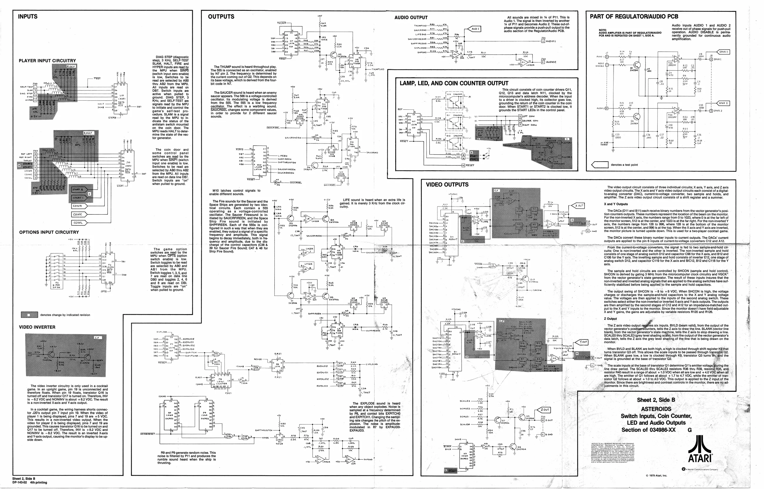
PART OF REGULATORIAUDIO PCB ‘Audio inputs AUDIO 1 and AUDIO 2 ior: receive out of phase signals for push-pull ‘AODIG aMPLinien 1s PART OF REquLATONAUDIO operation. AUDIO DISABLE Is perma- PCB AND IS REPEATED ON SHEET 1, SIDE A rently. grounded for continuous. audio ‘amplification. OUTPUTS 7 AUDIO OUTPUT Al sounds are mixed in %4 of P11. Tis is ‘Audio The signals then inverted by nother sao ‘eof Pit and becomes Audio 2. These outotphase signals provide a push-pull output the [Rio section ofthe RegulatovAudio PCB.
top) 3 Ree, SELETEST
| step) | 3 | Rie | Sele |
| PLAYER INPUT CIRCUITRY | i | ee |
= np are the MPU. when “SINFO {ewiten input 2a enable) ‘The THUMP sound is heard throughout play. ‘The 555 is connected as an oscillator, enabled by N7 pin 2. The frequency is determined by
- i; is low, Switches to be {he currant coming out of G2. This depends on AAA ‘ead are selected by ABO ite base voltage, which is derived from the four
| sneresft | TAS | e | ” | thu AB form the MPU. | bit code In N7. | LAMP, LED, AND COIN COUNTER OUTPUT |
| sul | : | foe | Oar."Beitoh inputs ae | Tis circuit consats of coin counter eevee G11, | |
| ue sreefe | R | sibs | active when pulled | ‘The SAUCER sound s heard when an enemy | (012, 19 and. data latch N11, clocked by the |
| ok | ee aes | round. DIAG STEP, 3 | ‘saucer appears. The $66 i a voltage-controlleg | mictocomputer's address decoder. When the input | |
| wvrerha) | ! | Kitz, and SELF-TEST ‘ae | ‘oscilator. Its modulating voltage is. derived | {o.a driver lo clocked high, Its collector goes low, |
from the’ $55. The 555 1s a low frequency gscllator. The effect Is a warbling sound. ‘changes some component values, in order provide for 2 aiferont saucer signals read by the MPU to initiate and control the game's self-test _proedure. SLAM is a signal ead by the MPU to in. icate the status of the antislam switch mounted fon the coin. door. The MPU reads HALT to deter. mine the state of the vec. tor generator. ‘grounding the return of the coin counter inthe coin ‘door. When START! or START2 is clocked low, it ‘grounds the START LEDs in the control panel. ——{Jier cow —FEeurer com
nage As ne
The coin door and
| some | control | panel |
switches arg_read by the MPU when SINPI (switen Input one enable) is low. ‘Switches to be read are selected by ABO thru AB2 oer from the MPU. All Inputs are read on data line DBT, ‘Switch inputs are “on when pulled to ground,
| eb | esf® | rea |
| aa | Bs | Shorinten |
< denotes a test point
“The video output cicult consists of three individual crcult; X axle, ¥ axis, and Z axis video output circuits. The X axis and Y axis video output circuits each consist ofa digital: toanalog converter (DAG), currentto-oltage converter, two sample and holds, and amplifier. The Z axis video output circuit consists of a shift register and a summer. M10 latches control signals to ‘enable different sounds. LIFE sound Is heard when an extra life is ‘gained. Itis merely 3 Kiz from the clock cir. “The Fire sounds for the Saucer and the ‘Space Ships are generated by two identical circuits. Each contain a 555 operating as a. voltage-controlled X and ¥ Outputs, ‘The DACs (D1 and B11) each receive binary numbers from the vector generator's posl- Oscllator The Saucer Fiesound te ir tion counters outputs. These numbers represent thelocatin ofthe bear onthe monitor. Siated by SAUCRFIREEN, andthe Space For the nominvered X axis, the numbers range from 0 fo 1028, wher@ 0s a the far fof
| [em | > | Ship. | Fire | sound. | is’ | initiated | by | * | {he monitor screen, S121s at the center, and 1023s. he fright. For the owinvertedY |
| SHBFIREEN. Each of the 8658 f8-con- | Lhe | peer | xis, the numbers range from 128 to 99, whore 128 ist the bottom of the monitor | ||||||
| figured in such a way that when they are | se | ar | Screen 5121s atthe contr, and 96 s | atthe top. When the XaxisandY axis aroiverted, | |||||
| OPTIONS INPUT CIRCUITRY | giles ny avouta ton ofasnacie | | | | ~, | oot | the monitor picture fe tumed upeide down. This ls uaod fora wopayer octal game. | ||||
| Begins to decay immediately, both in fro- | cs | berom| | ‘The DACS convert these binary number inputs fo cuent outputs. The DACs current | ||||||
| aency and amos ae to the ci | ete | coulputs are applied tothe pin 6 nputs | of curenttowltage converters C12 and AY2 | ||||||
| 2 | harge | of the control Sepactora | : | : | eiclaihs | ||||
| j | Ti: | Gans] | oper | $8 tor Saucer Fre Sound GAT | 98 for | From the curtenttovotage converters the signals fed fo two saripleand hold c- | |||
| lb [a | switches ‘are read by the | Ship Fire Sound). | | | ‘cuits: One is non-inverted and the other is inverted. The non-inverted sample and hold | |||||
| age | gaticion oe rod by the | Sonsits ef one sage of analog switch D2 and capacitor GBs for heX alo and B12 and | |||||||
| mar | Sater enable iow | 06 forthe ¥ als: The inverting sample and hold consits of inverter E12; one stage of | |||||||
| meme | a | q | ‘analog switch D12, and capacitor C118 for the X axis and BIC12, B12 and C118 for the Y | ||||||
| Fs | itch | toggles to be read | a | aa | |||||
| lea Soe | ‘are selected by ABO and | av | rm — | ||||||
| ibe age | Sah | fom ue et | The sample and hold circuits are controlled by SHCON (sample and hold control). | ||||||
| Se | eon | Suite toggles 1 9,5, and | £ | \ | SHCON ts derveo by gating ® MHz from the microcomputer cick creuty and VGGK | ||||
| ah | Teaneck | aw | irom the vector generators state generator. The result of these inputs Ineues thatthe | ||||||
| a | 80 and toggee | 2 | NB | fonvrtdanolnvried analog sash | are aplodo te salop etches have st | ||||
| ae | wae Womens | x | ficiently stabilized before being applied to the sample and hold capacitors. | ||||||
| when pulled to ground. | pei | ‘The output swing of SHCON is —8 to +8 VDC. When SHCON is high, the voltage |
charges or discharges the sampleand-hold capacitors to the X and Y analog voltage I value. The voltages are then applied to the inputs of the second analog switch. These ‘Switches select elther the non inverted or inverted X-axis and Y-axis outputs. The outputs are then amplified by the second stages of C12 and A12 for an impedance-matched out-
| yon | But to the X and Y inputs to the monitor. | Since the monitor doesn't have field-adjustable |
X and Y gains, the gains are adjustable by variable resistors R120 and R128, [EE ones chara y nats reson
VIDEO INVERTER Z Output TH82 aie vdeo cup ogi abi taps BVLD an vali, rom the ouput ofthe vector generators positigrreounters, tells the Z axis to draw the line. BLANK (vector line peerage meen reg igs Mere ent “I SCALED thru SCALES (grey lvel shading Sele), rom the output ofthe Vector gonerators
| sneur | te | dala latch, tells the Z axis the grey level shading ofthe line that is being drawn on the |
prover ‘monitor. " Sree \When BVLD and BLANK are both high, a high i clocked through shift register K@ithat tums transistor Q3 off. This allows the seale inputs to be passed through transistor Q2. When BLANK goes low, a Tow Is clockod through K8, transistor Q3 turns @n, and the f=] ee" signal is grounded at the base of transistor G2. : Bree eer “Te scale inputs atthe base of transistor Q1 determine Q's emitter voltage(furng the : *; line draw period. The SCALEO thru SCALES resistors R36 thru R39, resi R35, and,
| tty | EE | resistor R40 rest in range of about +1.0VDG when all are low and +0 VOC whon all | |||
| eat | / | fre high, The emitter of Ot folows at about + 1.7 to 47 VOC, while tho emitter of ran | |||
| al | “sv | — | i | sistor Q2 follows at about + | 1.0 to 4.0 VDC. This output is applied to the Z input of the |
_ptmonitor Since there are rightnese and conest contol inthe monitor, there ae no ad-
| ‘The video inverter circuitry is only used in a cocktail | _p@hustments inthis circut. | a |
game, in an upright game, pin 19 Is unconnected and lew ci {orefore floats: When pit 19 oats, transistor Q1e ie Sumer : tumed off and transistor 217 Is turned on. Therefore, INV. is -82 VOC and NONINV is about +82 VDC. The result
| is a noninverted X-axis and Y-axis output. | Js | Ya | ‘The EXPLODE sound is heard | Sheet 2, Side B |
Aue win any object plod. Noses
| Ina cocktail game, the wiring harness shorts connec- | fe | ae | Sampled tc Recumncy data | ASTEROIDS | |
| tor u20s ouput pin'7 input pin. When the ie of | Ie | nok | By Pa and. contol bis, EXPTTCND | F | |
| Blayor 1s being slaplayed, pina 7 and 19 are +8 VOC. | fe | she Sle | land EXPITCHT, Changing the sampy- | Switch Inputs, Coin Counter, | |
| This results in @ non-inverted video output. When the | i‘; | ag | ing rate changes the pitch of the ex- | ‘ | |
| Video or ayo 2s belo sloplaed, pie 7 and 10 are | ke, | “5 | se | poston. The nee 1 empinude | LED and Audio Outputs |
| Srounded THs causes ratelstor Goto bo urnedon and | ey | Ba | st | frodutied"in "Rr by EXPAUDS. | - |
| Q17 to be tumed off. Therefore, INV is +82 VOC and | = | suorunvsren | EXPAUDS. | Section of 034986-XX |
NONINV is 82 YOO, The resis an iwerted Kas sewwvese
| and Y-axis ouput, causing the monitor daplay tobe up | SE | Tay | — soe |
Sao down
'R9 and P9 generate random noise. This. noise is fitered by P11 and produces the rumble sound heard when the ship is ‘thrusting,
© 1979 ata, z ‘Sheet 2, Side B " 7 DP-143.02 4th printing