Trog Operations Manual (16-40003A-101) Sep 1990
Trog (rev LA5 3/29/91) (Midway, 1990) · Manual · 62 pages · 49 sections · original scan
September 1990 16-40003A-+101
MIDWAY
W PLAY masa
OPERATIONS MANUAL
ONE to FOUR PLAYERS
SEE EOE
MIDWAY MANUFACTURING COMPANY
TROG
The Legend of
N P LAY mation! "
Long, long ago, In aland named OG- There lived a One-eyed Caveman by the name of TROG |
And in that land There lived four friends- REX and BLOOP, SPIKE and GWEN |
They need your help to get home you see- For if you don‘tlead them - TROG'S DINNER they'll be |
TROG Is always thinking, Inventing something new- The wheel and the club and the bouncing spring shoe |
When they‘’ve picked up all thelr eggs, You'll see them smile and shout- “Cause leading Dinos HOME \s what the game’s about I
TABLE OF CONTENTS
Section 1 Operation and Troubleshooting
SOMON/o..cscsccssssessssssssssnnssssseessssssssssseennseceeenissuusssussssssceececeeesesstussssssenstssnsessesee jensen D2 Set-up Procedure Installation & Inspection. Location Requirements. Cabinet Assembly Diagram Servicing. Game Features Starting-up... Player Controls. 1-7 Control Panel Diagram. 1-7 Game Operation CONtOISWIHCHES. eesseeessssessaseeees r Control Switch Location Diagram, Game Adjustment & Diagnostics Starting-up...... 1-9 Main Test Men 1-9 Diagnostic Tests. 1-10 Switch T 1-10 DIP Switch Test & Chai 1-11 CPU & Sound Tests... 1-12 Monitor Ratterns & Bum-in Tests. 1-13 Coin Bookkeeping. 1-14 Game Audits...... 1-14 Game Adjusiments. 1-16 Standard Pricing Chart. 1-19 Utilities... 1-20 Troubleshooting. 1-21
Section 2 Parts Information
Cabinet. Speaker, & Lamp Parts.. sees Qe PC Boards, Transformer, Control Panel, 2.3 Cables, & Manuals. 2-4 Audio Board. 2-5 CPUBoard.. 26 PowerSupply. 2-8
Section 3 Diagrams and Schematics
JAMMA Edge Connector Chart. Audio Board Layout... Audio Board Schematic. CPUDiagram.. CPUSchematic. Cabinet Wiring Diag! . Control Panel Diagram Power Wiring Diagram. Interboard Wiring Diagram. Control Panel Wire Colors... COPYRIGHT 1990 MIDWAY MANUFACTURING COMPANY ALL RIGHTS RESERVED
RULES
Up to four people can play simultaneously.
Each person chooses their own DINO, Rex, Bloop, Spike, or Gwen.
Use the joystick to move the DINO.
Press the PUNCH Button to make the DINO PUNCH.
Pick up a HOT CHILI PEPPER and press the PUNCH Button to make the DINO FIRE.
Pick up all of your DINOS EGGS to reveal HOME.
The first DINO HOME WINS.
Keep DINOS away from DANGEROUS areas, like the EDGE OF THE WATER and THE PITS.
Especially, keep DINOS away from TROG.
TROG
Operation and Troubleshooting
Safety Notices
The following safety hints apply to all game operators and service personnel. Specific wamings and cautions will be found throughout this manual where they apply. We recommend that youread this page, and alsoallof Section 1,before preparing your game for play.
WARNINGS AC POWER CONNECTION. Before connecting the game to the AC power source, verify that the ‘line voltage selection chart" Jumper wires are installed Correctly for the line voltage in your area. For details, refer to Section 3.
PROPERLY GROUND THE GAME. To avoid electrical shocks, do not plug in the game until it has been inspected and properly grounded. Midway games should only be plugged into a grounded 3-wire outlet. Shocks will also result, if the contro! panel is not properly grounded! After servicing any parts on the panel, assure that the ground wires are secure. *. Onlythen should youlockupthe game.
DISCONNECT POWER DURING REPAIRS. To avoid electrical shock, disconnect the game from the AC power source before removing or repairing any part of the game. When removing or repairing the monitor, extra precautions must betakento avoidelectrical shock because high vottages may exist within the monitor circuitry and cathode ray tube (crt) even after power has been disconnected. Do not touch Interna! parts of the display with yourhandsormetal objects! Always discharge the crt: attachone end of a large. welkinsulated, 20-kV jumper to ground. Momentarlly touch
the free endofthe groundedjumpertothe anode bysliding ttunderthe anode
cap. Waittwo minutesand discharge the anodeagain.
USE THE PROPERFUSE. To avoid electrical shock, use the replacement fuse which is specified in the parts list for this game. The replacement fuse must match the original fuse in fuse type, voltage rating, and current rating.
HANDLE FLUORESCENT TUBE AND CRT WITH CARE. If you drop a fluorescent tube or CRT and it breaks, it will implode! Shattered glass can fly eight feet or more from the implosion.
PROPERLY ATTACH ALL CONNECTORS. Moke sure that the connectors on each printed circuit board (pcb) are properly connected. If they do not slip on easily, do not force them. A reversed connectormay damage your game and void the warranty. Allconnectors are keyed to fit specific pins oneachboard.
1-2
Setup Procedure
Installation and Inspection
- Remove the game from Its shipping carton, and Inspect the exterior of the cabinet for any signs of damage. Remove the shipping cleats from the bottom of the cabinet.
- Remove keys from the taped coin return slot (or attached to Joystick). Unlock and open the coin and cash box doors. (Leg levellers and spare parts are stored In the cash box.)
- Locate the four threaded holes on the bottom of the cabinet (ene In each comer),and Install one leg leveller (with Its hex nut) in each hole.
4, Stand the cabinet upright and make certain that It isin astable Position. Level the cabinet.
- Unscrew (or unlock) and remove the rear doors/panels of the cabinet. Inspect the interior for any signs of damage. Check all major assemblies to assure that they are mounted securely.
- Refer to the game's cabinet wiring diagram (Section 3), and check tosee that allcable connectors are correctly securedand firmly seated. DO NOT FORCE CONNECTORS. Watch for damaged connectors and avoid making reversed connections.
- Line Voltage Selection. Your games designed to work properly on the line voitage where you are located. Determine the value of your line voltage with a meter. Then, check the power Input wires to the main power supply transformer on your game to be sure they are connected to taps which correspond to your local line voltage value, Ifnecessary, reconnect the power Input wires to the transformer In accordance with the Tranformer Chart In Secton 3,
If the line voltage In your area falls outside the upper orlower limits of the range of voltage Inputs covered by the main powersupply transformer, DO NOT PLUG YOUR GAME IN until you have contacted your distributor or the Midway Service Department and obtained a solution to the problem. Otherwise, you could damage your game.
- Lay the lIne cord (connected to the Power Chassis) in the siot along the bottom edge of the lower rear cabinet door/panel. Install the rear cabinet doors/panels and screw (lock) them securely. Close and lock the front coin and cash box doors.
- Connect the IIne cord to a grounded (3-terminal) AC wall outlet.
- Switch ON the game, using the ON/OFF switch located onthe upper left rear of the cabinet, to verify proper operation.
1-3 GAME LOCATION REQUIREMENTS
Power Domestic 115V @ 60 Hz Foreign 230V @ 50 Hz
Temp. 32° F to 100° F (0° C to 38° C)
Humidity Not to exceed 95% relative.
On/Off
TROG Cabinet Assembly
Servicing
Servicing the Control Panel
Switch OFF power to the game. The control panel Is held Inplace by fourlatches(locatedon the left andright sides of the cabinet) which provide constant pressure on the strikes. The latchescan bereached through the coin door opening. To release the latches, lift the latch handle and unhook the wire fasteners. Carefully use the Joysticks to lift the control panel. Rest the panel on Its support bracket, while working on It. To reinstall the control panel, check for Proper cable connections, Including the ground strap, and use the Joysticks to lower It into position, avoiding pinched wires. Reclamp the latches.
Removal of Viewing Glass
Switch OFF power to the game, and open the control panel. Unscrew the fournuts atthe bottom ofthe glassand remove the protective black plastic strip. Carefully liftthe glass from Its bottom groove andiiftit clear of the cabinet.
Removal of Monitor Bezel Switch OFF power to the game, and remove the viewing glass, Remove the bezel securing screws to free the monitor bezel.
Monitor Replacement
We recommend that you read the WARNINGS section thoroughly before beginning this procedure. Switch OFF power to the game. Open the upper rear door/panel. Remove the viewing glass and the monitor bezel. Completely disconnect the monitor from all of Its cabling, including Its chassis ground strap. Remove the four bolts securing the monitor's mounting flanges to Its mounting panel. Pull the monitor carefully from the cabinet front. To preserve color purty of the monitor, when moving the game be sure the power Is tumed OFF.
The monitor DOES NOT contain an Isolation transformer In Its chassis (it ls mounted Instead in the Power Chassis Assembly located on the floor of the cablnet). When servicing the monitor ona test bench, YOU MUST ISO- LATETHEMONITOR FROM THELINE VOLTAGE WITH AN ISOLATION TRANSFORMER.
While removing the four bolts, firmly support the monitor from the front of the CRT so that If will not slip.
@ Removal of the Marquee Glass Switch OFF powerto the game. Remove thescrewsinthe black plastic strip on top of the cabinet. Remove the strip " and carefully lift the glass. Store the glass carefully to
i Removal of the Fluorescent Light
Assembly
Switch OFF power to the game. Remove the marquee glass. Disconnect the fluorescent light assembly from Its power cable. Remove thescrews fastening the assembly to the cabinet and lift out the assembly.
@ Removal of the Speakers Switch OFF power to the game. Remove the upper rear cabinet door/panel, taking care to not damage the speaker enclosure seals. Disconnect the speakers from thelrcabling. Remove the nuts on the speaker mounting bolts. Remove the speakers. Because the speakers are mountedin anacoustical enclosure, carefully reinstall the seals upon completing any task In the speaker enclosure.
@ Volume Control, Test/Diagnostics Switch, and Service Credit Switch Open the coin door to locate the game's volume control and Diagnostic switches on the small panel atop the cash box cover. The Volume Control Is the white knob on left end of the panel. Turning the knob clockwise Increases the volume. The upper right switch on the bracket Is the Test/Diagnostics Switch that enables activating the game's test mode. The lower right switch Is the Service Credit Switch, which allows adding credits toa game for service testing without affecting the game's bookkeeping total.
1-6
Game Features
Starting Up
Switch ON powerto the game. A "rug" pattem appearson the CRT screen. When the ‘rug’ pattern ends, the screen shows CHECKING SCRATCH RAMS, and then CHECKING ROMS, The next screen shows TROG REVISION LEVEL, CMOS TEST OK and the COIN SETTING. The game then movesto the attract mode. After the proper coinage has been Inseried, the game exits the attract mode and enters the play mode.
Player Controls
El Each START button cllows the player to choose a Dino. BLOOP (blue); GWEN (purple); SPIKE (yellow); and REX (red).
Each PUNCH button allows the player to either Punch or Fire. Press Punch to make your Dino punch. Pick up a HOT CHILI PEPPER and press Punch to make your Dino Fire.
i Each JOYSTICK allows each player to move their Dino up, down, left, or right.
Rex Bloop “© ‘Start Button
Bloop Move T wos, . Spike Punch Button Punch Button TROG is a one- to-four player game. Each player chooses his/her own DINO. Any combination of DINOS can be played simultaneously.
TROG willl operate In the Test Mode, when the Test Switch (on the cash box cover) Is closed or DIP Switch Bank #2 Switch #8 Is closed.
When an error Is detected during Start-up Tests, game start-up does not progress, and an error message appears on the screen.
Typical TROG Control Panel for FOUR Players
Game Operation
TROG Is a one- to four-player video game with a color monitor. From the player's perspective, the game has two modes of operation: Ready-to-Play and Play. Forthe owner/ operator, the game has an additional mode of operation called Game Audit, Adjustments and Diagnostics.
Control Switches
ES] The VOLUME CONTROL allows Increasing or decreasing the volume level of the game music and speech. For greater profits, set your game's volume level at Its maximum.
FE] The TEST/DIAGNOSTICS SWITCH allows you to enter Into the game's Diagnostic mode. Turn the Test Switch ON to enter the Diagnostics mode. To exit this mode, turn the Test Switch OFF. Game diagnostics can be reached via the DIP Switches also.
=] The SERVICE CREDIT SWITCH is a special feature switch that allots credit without affecting the game's bookkeeping total.
£2] The COIN DOOR SLAM TILT SWITCH detects any forceful vibrations against the Coin Door. This eliminates pound- Ing for free games.
—] The POWER INTERLOCK SWITCH Is a safety switch that ensures power to the game Is off during servicing. This switch Is located Inside the rear door/panel.
Volume Centro!
Control Switch Locations
1-8
Game Audits, Adjustments &
Diagnostics
Operation
All TROG Game Audits, Adjustments, and Diagnostics are options of the Main Test Menu. Each option, In turn, has Its own menu, listing several choices that you may act upon as desired.
To enter the Main Menu, turn ON the Test Switch (on the cash box cover), or turn ON DIP Switch #8 In switch bank 2. The Main Test Menu (shown below) then appears. Game adjustments, bookkeeping, and diagnostics are allaccessible from thls menu.
Move any joystick up or down to cycle through the menu options. Notice that the options are highlighted In sequence. Selecting a desired optionrequlres|tto be highlighted. To activate the selected option, press any control panel button.
To exit, use any Joystick to highlight Exit To Game Over and tum OFF either the Test Switch or DIP Switch #8 In switch bank 2.
The Main Test Menu lists six options.
SELECT WITH UP/DOWN STICK ACTIVATE WITH ANY BUTTON
DIAGNOSTIC TESTS
COIN BOOKKEEPING
GAME AUDITS
GAME ADJUSTMENTS
UTILITIES
EXIT TO GAME OVER )
Main Test Menu
1-9
DIAGNOSTIC TESTS To enter the Diagnostic Tests from the Main Test Menu, move any Joystick to select (highlight) the Diagnostic Tests option, and press any control panel button to activate the option.
The Diagnostic Tests Menu lists seven options.
SELECT WITH UP/DOWN STICK ACTIVATE WITH ANY BUTTON.
SWITCH TEST
DIP SWITCH TEST
CPU BOARD TEST
SOUND BOARD TEST
MONITOR PATTERNS
BURN-IN TEST
RETURN TO MAIN MENU
Diagnostic Test Menu w
Switch Test The Switch Test allows the operator to test the switches on the contro! panel and the coin door.
Select the Switch Test by using any Joystick to highlight the Swltch Test option; then, press any control panel button to activate lt. Thescreen showsthe controlpaneland coin door switches. Pressing a switch causes the corresponding switch location on the screen to light. Release the switch and the screen returns to normal.
Press both Player 1 Punch and Player 1 Start Buttons to return to the Diagnostic Menu.
1-10
DIP Switch Test The DIP Switch Test allows the operator to check the position of the two 8-position DIP switches on the CPU Board. The operator can also change the setting of each position of each DIP switch during this mode.
Select the DIP Switch Test by moving any Joystick to highlight the DIP Switch Test option; then, press any contro! panel button to activate the test. The screen displays alayout of the DIP switches and their current settings.
To change the setting of elther DIP switch, press the switch position (SW1 - SW8) to the desired setting (ON from OFF, or vice versa). Check the screen to verify that the switch now shows the setting desired.
Press any control panel button to retum to the Diagnostic Test Menu: DIP Switch 1 Settings Table [| i SC:C*ds Sst | Sw Sw] Sw Sw swe] SW77] Swe] Upright Midway Cocktail
Coin Settings Gert Fra Ger 2 Ger3 Ger 4 Ger ECA NU NU Free Play
3 Players 2 Players 1 Player Video Freeze (activates when change detected. Test Switch Game Mode Test Mode
- Indicates Factory Setting
Assoon as a faulty chip Is detected, the CPU Test stops. The remaining chips are not tested. CPU Board Test The CPU Board Test (muchike the Start-up Test) allows the operator to check the RAMs and ROMs.
Move any Joystick to select the CPU Board Test; then, press any control panel button to activate the automatic test of the CPU Board's RAMs and ROMs, When this test Is activated, a ‘tug” pattem appears on the screen. The screen then changes to show the layout of the RAMs, and ROMs on the CPU. Any chip that is shown as black with a white outline Is part of the CPU and should tum elther red or green during the CPU Test. Any chip that Is shown as gray with a white outline Is not installed in the game. During the test, chips are good, if they turn green; they are faulty, If they tum red.
\fno errors are detected, the screen automatically retums to the Diagnostic Menu.
Sound Board Test The Sound Test allows listening to some of the sounds that TROG Is capable of producing. This test also emits a tone for each fault that Is detected.
Move any joystick to select the Sound Board Test; then, press any control panel button to activate the test. The screen displays two test options:
GENERAL TEST analyzes the sound circultry. A successful test causes a single "tone’ to sound. Detection of a fault causes aseries of tones, or no tone at all to sound.
PLAY SOUNDS fests synthesized sounds from the SoundBoard. Press any Punch Button to advance to the next sound.
To exit this test, use any Joystick to select Back to Diagnostic Menu, or Retum to Main Menu; then press any control panel button,
GENERAL TEST
PLAY SOUNDS
| BACK TO DIAGNOSTIC MENU RETURN TO MAIN MENU
Sound Test Menu
1-12
Monitor Patterns The Monitor Patterns Test provides a menu for testing the monitor.
Move any Joystick to select a test; press any control panel button to activate the test.
SELECT WITH UP/DOWN STICK ACTIVATE WITH ANY BUTTON.
RED SCREEN »
GREEN SCREEN
BLUE SCREEN
COLOR BARS
CROSSHATCH PATTERNS
BACK TO DIAGNOSTIC MENU RETURN TO MAIN MENU
Monitor Pattern Menu The RED, GREEN, and BLUE SCREEN tests fill the screen with elther red, green or blue. The COLOR BARS test fills the screen with several gradiated colors to help with red, green and, blue level adjustments. Each color should appear sharp and clear. The CROSSHATCH PATTERNS test fills the screen with a grid and a serles of dots. The grid and the dots should be clear, The dots should appear round,
Exit this test by pressing any control panel button to retum to the Monitor Patterns Menu. Use any Joystick to select Back to Diagnostic Menu, or Return to Main Menu; then press any control panel button.
Burn-in Test The Burn-in Test continually repeats the CPU Board Test. Move any Joystick to select the Bum-in Test; then, press any button to activate the test. When the Burn-in Test detects an error, the test stops and displays an error message on the screen. The third page of the Audit Table specifies the number of Burn-in cycles successfully completed. Use this test to find intermittent CPU problems.
To exit this test, switch OFF the game; then, switch It ON again.
1-13 TROG provides front-mounted Monitor Board controls. These controls are accessible within the control panel opening beneath the monitor.
COIN BOOKKEEPING To enter the Coin Bookkeeping from the Main Test Menu, move any Joystick to select the Coin Bookkeeping option; then, press any control panel button to activate It.
The Coin Bookkeeping Table records the coinbox totals and game play counters. The left side of the table names the bookkeeping Item: the right side shows the number of coins, credits, or plays for each Item.
S\ LEFT SLOT COIN
RIGHT SLOT COIN
THIRD SLOT COIN
FOURTH SLOT COIN
SERVICE CREDITS
PAID CREDITS
GAMES STARTED
GAMES CONTINUED oooeaeoeae eo eo eo oe TOTAL PLAYS
PLAYS UNTIL HIGH SCORE RESET 5000
MORE DETAILED INFORMATION RETURN TO MAIN MENU
Coin Bookkeeping Table
To exit Coin Bookkeeping, move any joystick to select RETURN TO MAIN MENU; then, press any control panel button to activate It.
GAME AUDITS To enter Game Audits from the Main Test Menu, move any Joystick to select the Game Audits option; then, press any button to activate It. To advance to the next (or retum to the previous) page of the Game Audit Table, move any Joystick to select elther ‘Next Audit Page", or "Previous Audit Page’; then, press any control pane! button to change the page.
The Game Audits Table records the game play statistics. The left side of the table names the Audit Item: the right side shows the amount of play.
1-14
XK TOTAL PLAYS TOTAL PLAY TIME TOTAL GAME UP TIME AVERAGE TIME/LIFE AVERAGE TIME/CREDIT TIME 1 PLAYER ONLY TIME 2 PLAYERS SIMULTANEOUS TIME 3 PLAYERS SIMULTANEOUS. TIME 4 PLAYERS SIMULTANEOUS
NEXT AUDIT PAGE RETURN TO MAIN MENU ooooooocosd
PAGE 1 OF AUDIT TABLE
TOTAL PLAYS AVERAGE CREDITS/GAME BEGINNER STARTS ADVANCED STARTS EXPERT STARTS AVERAGE WAVE REACHED GAMES PLAYED TO COMPLETION MAXIMUM WAVE COMPLETED
NEXT AUDIT PAGE PREVIOUS AUDIT PAGE RETURN TO MAIN MENU eoccoceo0nd
PAGE 2 OF AUDIT TABLE
TOTAL EXTRA DINOS EARNED GAME CONTINUES OFFERED GAME CONTINUES TAKEN PERCENTAGE OF CONTINUES TAKEN, COIN DOOR SLAMS BURN-IN LOOPS SUCCESSFULLY COMPLETED
PREVIOUS AUDIT PAGE RETURN TO MAIN MENU oooooo
w, PAGE 3 OF AUDIT TABLE
To exit the Game Audit Table , move any Joystick to select RETURN TO MAIN MENU; then, press any control panel button to activate It.
GAME ADJUSTMENTS Move any Joystick to select the Game Adjustment option on the Main Test Menu; then, press any control panel button to activate It.
The Game Adjustments option allows the owner/operator to change the Game Pricing and Game Difficulty.
The Game Adjustment Menu offers 12 cholces. Several of these cholces have thelr own menu. Move any Joystick to select your choice from the Game Adjustments Menu; then, press any control panel button to activate that choice, On thenext menu, elther move any Joystick to select the Item you wish to modify; then, press any contro! panel button to activate that Item, or If the Item only provides a setting choice, move any Joystick to change the current setting to the desired value; then, press any conirol panel button to lock In the desired value. Moving the Joystick up Increases the setting value shown on the screen. Moving the Joystick down causes the value shown on the screen to decrease.
SELECT WITH UP/DOWN STICK PRESS ANY BUTTON TO MODIFY
RETURN TO MAIN MENU )
STANDARD PRICING
CUSTOM PRICING
GAME DIFFICULTY
LIVES PER PLAY
EXTRA MAN EVERY
NUMBER OF EXTRA MEN
AUTO HIGH SCORE RESET
FREE PLAY
HIGH SCORE ENTRY
ALLOW GAME CONTINUE
RETURN TO MAIN MENU
1-16 Game Adjustment Menu
Standard Pricing
Standard Pricing allows the operator to choose any of the “Standard” selections for the Standard Pricing Table. Standard Pricing cannot be installed when elther Custom or DIP Switch Pricing Is In effect.
Press any control panel button to lock In the selected setting and return to the Game Adjustments Menu.
Custom Pricing
Custom Pricing allows the operator to Install pricing other than that of the Standard Pricing Table. Custom Pricing also allows the operatorto select the maximum amount ofcredits per game, the amount of credits required to start a game, and the amount or credits required to continue a game. Custom Pricing cannotbe Installed when DIP Switch Pricing Is In effect.
Press any control panel button to lock in the selected setting and return to the Game Adjustments Menu.
Game Difficulty
Game Difficulty allows the operator to select the difficulty level of the game. The range of this setting |s Easlest (1) to Hardest (10).
Press any control panel button to lock In the selected setting and return to the Game Adjustments Menu.
Lives per Play Lives perPlay allows the operatorto select the number ofllves aplayer recelves each time a game |s started or continued.
Press any control panei button to lock In the selected setting and retum to the Game Adjustments Menu.
Extra Man Every
Extra Man Every allows the operator determine how many points the player must earn before recelving an extra life.
Press any Control panel button to lock in the selected setting and return to the Game Adjustments Menu.
Number of Extra Men Number of Extra Men allows the operator to determine how many men the player can eam per credit.
Press any control panel button to lock in the selected setting and return to the Game Adjustments Menu.
1-17 The TROG Standard Pricing Table Is on page 1-19,
Auto High Score Reset
Auto High Score Reset allows the operator to determine how many plays must occur before the all time high scores are automatically reset to factory settings.
Press any control panel button to lock In the selected setting and retum to the Game Adjustments Menu.
Free Play
Free Play allows the operator to determine whether game play can occur without any coins being dropped Into the coin chutes. Free Play cannotbe Installed when DIP Switch Pricing Is in effect.
Press any control pane! button to lock In the selected setting and return to the Game Adjustments Menu.
High Score Entry
Allows the operator to determine whether the game hes a High Score Eniry Table and Display.
Press any control panel button to lock in the selected setting and return to the Game Adjustments Menu.
Allow Game Continue Allow Game Continue allows the operator to determine whether a player can continue to play even though all other players are dead.
Press any contro! panel button to lock In the selected setting and return to the Game Adjustments Menu.
To return to the Main Test Menu, move any Joystick to select RETURN TO MAIN MENU; then, press any control panel button to activate the return.
1-18
NAME
USA1 USA 2 USA3 USA 4 USA ECA
German 1 German 2 German 3 German 4 German ECA
France 1 France 2 France 3 France 4 France ECA
TROG Standard Pricing Table
1/50¢, 3/$1.00 1/50¢, 4/$1.00 1/25¢, 4/$1.00
1/1 DM, 6/5 DM 1/1 DM, 7/5 DM 1/1 DM, 8/5 DM 1/1 DM, 5/5 DM 1/1 DM, 2/2 DM, 6/5 DM
2/5 F, 5/10 F 2/5 F, 4/10 F 1/5 F, 3/10 F 1/5 F, 2/10 F 1/3 X1F, 2/5 F, 5/2X5F
1/1 F, 6/5 F
1/500 Lire
1/20 P, 3/50 P 1/30 P, 2/50 P, 4/£1.00
1/25 Peseta, 5/100 Peseta
1/100 Yen 500 Lire
25 Peseta
100 Yen
If option desired is not shown above, use custom pricing .
1-19 CENTER
UTILITIES On the MainTest Menu, move any joystick to select the Utilities option; then, press any contro! pane! button to activate It.
The Utilities option allows the owner/operator to clear the game's bookkeeping memory and to Install a custom message.
SELECT WITH UP/DOWN STICK ACTIVATE WITH ANY BUTTON
OPERATOR MESSAGE
CLEAR CREDITS
CLEAR COIN COUNTERS
CLEAR GAME AUDITS
RESET HIGH SCORE
DEFAULT ADJUSTMENTS
FULL FACTORY RESTORE
RETURN TO MAIN MENU
Utilities Menu S/S
Move any joystick to select an Item from the Utilities Menu; then, press any control panel button to activate that tem. After anitem hasbeen activated, you are given the option of resetting the item or not. For example;
CLEAR CREDITS ARE YOU SURE ?
[NO |
Move any joystick to choose YES or NO; then, press any contro! panel button to lockin yourcholce andtoretum to the Utilities Menu.
To exit Utilities, move any Joystick to select RETURN TO MAIN MENU; then, press any control panel button to activate Ht.
1-20
Troubleshooting
Problem
NO PICTURE OR DISTORTED PICTURE.
TURN GAME ON & NOTHING HAPPENS
NO SOUND
NO GENERAL ILLUMINATION
MOVE JOYSTICK, BUT DINO DOES NOT MOVE
PRESS START or PUNCH BUTTON AND NOTHING HAPPENS
NO CREDIT GIVEN WHEN COINS ARE INSERTED
TOO MANY CREDITS FOR NUMBER OF COINS INSERTED
GAME STAYS IN THE TEST MODE. Possible Solution
Check for faulty video board or monitor. Check for disconnected video signal cable.
Check line fuse. Check for +5V de at pins C, D, 3, and 4 of the JAMMA Connector.
Check the speaker and speaker connection to pins L and 10 on JAMMA Connector. Check volume control setting. Check for +12V de at pins F and 6 on the JAMMA Connector. Check interboard wiring from CPU Board to Sound Board,
Check the 1A., S-B fuse on the cabinet wall above the coin box.
Check for open wires between Joystick and CPU Board. Check for contamination on joystick switch contacts and CPU Board pins. Check for proper ground.
Check for open wires between button and CPU Board. Check for contamination on CPU Board pins or button switch blade contacts. Check for proper ground.
Check DIP switch coin setting. Check for contamination on coin switch contacts. Check foran open wire between Coln Switch 1 and pin 16 on JAMMA Connector or Coin Switch 2 and pin T of JAMMA Connector.
Check Game Pricing setting. Check for a short between pins T & 16 on JAMMA Connector.
Check that the Test Switch (on the cash box cover) and the Test Switch (Position 8) on DIP Switch 2 are set to OFF.
1-21
Notes
1-22
TROG
SECTION two
Parts Information
Cabinet Hardware
Cabinet Assembly A-11-933-4005 Caster Wheel Assembly B-13086 Leg Leveler Plate 01-9155 Leg Adjuster 08-7377
Back Door Assembly B-13574 Lock Retainer 01-7264 Upper Door Lock Cam 01-8989 Rear Wood Door 11-934 Door Cam Lock 20-6542-TB
Line Voltage Cable Assembly C-12773-4 Mig Pit Toggle Assembly A-9958 Interlock Spring Brkt. Assy B-12907 Une Voltage Cable H-13555 Protective Cap 17-1038-2 Toggle Switch 5640-10932-00 Interlock Cheat Switch 5643-09556-00
Over/Under Coin Door D-13250 Test Switch A-13115 Coin Door Cable H-13215 Coin Door USA 09-20000-V-1 12 pin 'Z' Header 5791-12235-12
Glass Retainer Bracket 01-9607 20" Vent Hole Cover 03-7602 Vent Hole Cover 03-7839 Marquee Retainer 03-8252-2 Lock Lamp 03-8327 Glass Edge Channel 03-8358 25° CRT Bezel 03-8387 Vent Hole Cover 03-8413 Speaker Wood Door 11-935 Toggle Latch 20-9347 TROG Marquee 31-1543-4005-U Glass CRT Cover 31-1544-4005-U Speaker Gullle 31-1553-4005-U
Speakers
Piezo Speaker Assembly B-13587 6’ Round Speaker, 4 ohm, 10W 5555-12015-00
Fluorescent Lamp
Fluorescent Housing & Bracket C-12679 Housing Mounting Brkt 01-9146 Ught Fixture 20-9590 18" Fluorescent Bulb, 15 W =. 24-8809
‘PC Boards
Y-Unit CPU Assembly C-13234-40003 Power Supply Assembly C-13253-1 Audio Sound Board Assembly D-11581-40003
Transformer Assembly
Power Pack Assembly D-13252 Line Cord Assembly A-13340 Power Transformer 5610-12559 Power Pack Chass! Assy C-13251 Power Pack Jumper Cable —H-13265 Line Filter Jumper Cable H-13344 Transformer Jumper Cable —_-H-13378 Varistor, 130V, 10J 5017-09044-00 Line Fliter, SAmp 5102-08895-00
Control Panel
Control Panel Assembly A-14174 Control Panel Plate Assembly C-13473 Blue Button Assembly C-9214-1 Purple Button Assembly C-9214-22 Red Button Assembly C-9214-4 Yellow Button Assembly C-9214-23 Control Panel Cable H-13556 Latch Bracket 01-6994 Latch Bracket 01-9605 Universal Switch Molding 03-7614 Wood Control Panel 11-942 5/8 Palnut 20-9222 Red Joystick 20-9662 Yellow Joystick 20-9662-4 Purple Joystick 20-9662-6 Blue Joystick 20-9662-8 Screened Overlay 31-5-40003
Monitor
Monitor 25° 5675-12621-00
Cables
Video Sound/Power Cable H-10217-4 Speaker Cable H-13213 Coln Door Cable H-13215 Sound/Power Speaker Cable H-13257 Volume Control Cable H-13258-2 Power Pack Jumper Cable H-13265 Une Filter Jumper Cable H-13344 Transformer Jumper Cable _ 1-13378 Main Hamess Cable : H-13554 Une Voltage Cable H-13555 Control Panel Cable H-13556 Piezo Speaker Cable H-13557 Ground Jumper Cable H-13953 20 pin Ribbon Cable 5795-10937-18
Manuals
Monitor Manual 16-3000-103 Instruction Manual 16-40003A-101
2-4
D-11581-40003 Audio Board Assembly
fe)
Part No. Ckt Designator Description
5766-12130-00 Bare P..C. Board
| 5971-11087-00 | Ut | IC, D/A Conv, YM3012 |
@) 5700-09006-00 Socket, {C, 16-pin (U1)
| 5370-11086-00 | U3. | {C, Sound Processor, YM2151 |
- 5700-08004-00 Socket, IC, 24-pin (U3)
| 400-10320-00 | UB | IC, pProcessor, MC68BO9E |
- 5700-08985-00 Socket, {C, 40-pin (U8)
| A-5343-40003-19 | U4 | IC, Audio ROM1 |
| ‘A-5343-40003-20 | U19 | IC, Audio ROM 2 |
| ‘A-5343-40003-21 | _U20 | IC, Audio ROM 3 |
- 5700-10176-00 Socket, IC, 28-pin (U4, U19)
| 5971-09152-00 | «U1 | IC, D/A Convtr, MC1408 |
| 5430-10322-00 | U2 | IC, PIA, McesB2t |
| 5340-10199-00 | US. | IC, RAMS 5516-2 2kx8 |
| 281-09487-00 | -U16 | {C, Dual D Filpfiop, 74LS74 |
| 5281-10043-00 | -U13. | (c, 74.8175 |
| 5281-09295-00 | U2 | IC,Triple NAND, 74LS10 |
5970-09321-00 U9, U10, U17, U18. IC, Op Amp, M1458
| 5281-09215-00 | U2 | IC, Hex inv, 74LS04 |
| 5281-00246-00 | U14 | (C, 2-4 Dec, 7418139 |
| 5281-09745-00 | U1 | IC, Dual Mux, 7415138 |
| 5970-00156-00 | _U22, U23 | IC, Audio Amp, TDA2002 |
- 5705-09199-00 Heatsink, #60308
- 4006-01003-06 Mach. Screw, 6-32 x 3/8 ©) 4406-01117-00 Nut, 6-32 Hex.
- 4703-00007-00 Lockwasher, #6 Ext.
| 5160-10269-00 | Qt | Transistor, 2N3904, NPN |
| 5060-10396-00 | SP1 | SIP 4.7K & 470pfd, 8RBC |
| 5010-09181-00 | R44, RAB | Resistor, 1.00, 1/2w, 5% |
| 5010-09161-00 | R35, R45 | Resistor, 2.29, 1/4w, 5% |
| 5010-09361-00 | R43, R46, R47 | Resistor, 22001, 1/2w, 5% |
| 5010-08358-00 | R41, R42 | Resistor, 1K, 1/4w, 5% |
So10-08998-00 © R2, R3, Resistor, 2.2K, 1/4w, 5%
| 5010-08983-00 | -R7-RO | Resistor, 3.3K, 1/4w, 5% |
5010-08991-00 1, 4, RS,R11, Resistor, 4.7K, 1/4w, 5% R25 - R28, R33, R36, R97, R49, R50 NOTES: Part No.
5010-10985-00 5010-09034-00 5010-09324-00 5010-08162-00 5010-09331-00 5010-08772-00 5010-08824-00 5010-08848-00 5010-08991-00 5010-09219-00 5010-10258-00 5010-09179-00 5010-09333-00 5010-09342-00 5010-09534-00 5040-09343-00 5040-10974-00 5040-09776-00 5040-12006-00 5041-00243-00 5043-08980-00 5043-08996-00 8043-09065-00 5043-09492-00 5043-09844-00 8043-09845-00
5520-08020-00 5521-10931-00 5551-09822-00 5791-00437-00 §781-10862-04 5791-10862-06 16-8850-250 20-9229
*" 17 capacitors (shown on dlegram with "B" symbol) provide +5VDC fitering for ICs. All capecttors era ceramic, 50v, axial, unless otherwise noted. All resistors are 5%, 1/4w, Carbon Film, unleas otherwise noted. (Ckt Deelgnator
R14, R15 Description
Resistor, 20K, 1/4w, 5% Rh22-R24, R17, R34 Reeistor, 10K, 1/4w, 5% 6, R19, R20, R21 Resistor, 27K, 1/4w, 5% R39 R16 Ris R32
C1, C3, C4, C8 C12, C19, C24 €26, C30 C29, C32 C25, C28 ¢5,B(17)" 31, C33 C13-C15 C2, C34 ce C16, C18, C20- 23, C27 xt CRI L1-L3 M4 1, 2, JS J3 Resistor, 100K, 1/4, 5% Resletor, 13K, 1/4W, 5% Resistor, 15KQ, 1/4W, 5% Resistor, 43K0, 1/4W, 5% Resistor, 220KA, 1/4W, 5% Resistor, 4.7KQ, 1/4W, 5% Resistor, 8.2K, 1/4W, 5% Resistor, 1M, 1/4w, 5% Resistor, 3.9M, 1/4, 5% Resistor, 180KQ, 1/4W, 5% Resistor, 36K0, 1/4W, 5% Resistor, 00, 1/4w, 5% Cepector, 101fd, 20v, 420% Capacitor, 100ufd, 35¥ Capactor, 470ufd, 16v; +50, -10% Capecttor, 1000ufd, 16v, 20% Capecttor, 10yfd, 10v.410% Cepacttor, 0.01pfd, 50v,+80, -20% Capecttor, 0.1pd, 50v, 420% Capacttor, 470 ptd, 50v, 20% Capacitor, 100 pid, 50v, 410% Capecttor, 47 pfd, 50v, 420% Capacitor, 1000 pd, 50v, 420%
Connector, 4 pin (Hdr) Connector, 6 pin (Hdr) P.C.B. LD. Label Thermal Compound
This page reads as a drawing: its text was drawn rather than typeset, and comes out in fragments. See the original scan.
Part No.
5770-12555-00 5281-09737-00 5317-12211-00
5317-12212-00
5317-12208-00
5340-12242-00 5700-12047-00 5340-12213-00 5521-12604-00 5521-10318-00 52B3-10468-00 5019-10849-00 5317-12305-00 5700-12253-00 5280-09309-00 5281-09487-00 5434-12255-00 5700-09915-00 5311-12287-00
5700-10176-00 5311-12285-00 5340-12014-00 5283-10552-00 5370-12602-00 5317-12023-00 5700-12088-00
5700-12254-00 5700-08985-00 5010--08991-09 5010-10204-00 5010-10205-00 5010-10090-00 5010-09219-00 5010-08772-00 5010-09001-00 5010-09036-00 5010-09416-00 5010-08997-00 5010-09534-00 C-13234-40003
Ckt.Designator
ut U2, U20, U24, U4 U61, U62, U70 U3, U6, U7, U21, U25 U50, U58, U63, U64 Description
Bare PC Brd. Ic, 74LS 86
IC, 74ALS541 T4ALS574
U71, U72, U74, U79, U84, U85 U4, U22, U54-U57 US59, U60, U75-U78 UB, UB1, U94, U110 U5, U23 U8, US2, U53, USS U10, U1, U28-U33 ut6 uI7 U19, U45 U27, U34, U44, U48, U35 U36
U39 U40-U42 U47, U46, UB7, U100 U101, U103, U104 ag U51, U73, U82 U66-U69 us3 us6 uss. U89-U93, U95-U9B UT05-U109, U111-U114 Uso uns R1,R24, R27 R2, R7, R12 R3, R8, R13 R4, RO, R14 RS, R10, R15 R6, R11, R16 R23, R25 R26, R29-R34 R35-R37, R46-R4B R38-R45 wa, Ws, W11, W12 W14, W20, W22, W24 we7, W28, W31, W32, W35, W39, W41, W43wad, W46, W48, W5O, W52, W54, W56, W58 W60, W62, W66, W68, W689, W72, W74, W76 W78, W80 74ALS245
Ic, 8Kx8 SRAM 24 pin Socket Ic, 4461 VRAM 40 MHZ Xtal 24 MHZ Xtal IC, 74F74 1900 DIP Res. Ic, 74ALS00 68 pin Socket Ie, 7407 Ic, 74.874 Ic, MAX691 20 pin Socket IC, 740541
28 pin Socket Ic, 74HC573 IC, 4464 DRAM IC, 74F04 Ic, ULN2064B IC, 74ALS138 32 pin Socket
144 pin Socket 40 pin Socket Res. 4.7K 5% 1/4W Res, 1KQ 2% 1/4W Res. 2KQ 2% 1/4W Res. 3.9K. 5% 1/4W Res, 8.205% 1/4W Res. 15K2 5%1/4W Res. 3302 5% 1/4W Res. 19002 5% 1/4W Res, 4702 5% 1/4W Res. 2.70 5% 1/4W Res. 02 Part No.
5043-08980-00 5040-08986-00 5043-09845-00 5041-09243-00 5043-8996-00 5019-12611-00
5019-09362-00
5019-10143-00 5060-10396-00
5671-09019-00 5551-09822-00 5645-09025-00 5641-12551-00 5881-12315-00 5791 -10862-08 5791-12461-12 5791-10859-00
5791-09437-00
5791-124-10 C-13235-2 A-5346-40003-1 5400-12220-00 A-5346-40003-2 A-5346-40003-3 A5346-40003-4 A5346-40003-5 A5346-40003-6 A-5346-40003-7 A-5343-40003-1 4-5343-40003-2 A-5343-40003-3 A-5343-40003-4 A-5343-40003-5 A-5343-40003-6 A-5343-40003-7 A-5343-40003-8 A-5343-40003-9 5410-12239-00 A-5343-40003-10 A-5343-40003-11 A-5343-40003-12 A-5343-40003-13 A-5343-40003-14 A-5343-40003-15 A-5343-40003-16 A-5343-40003-17 A-5343-40003-18 A-5343-40003-8 5880-11056-00 03-8338-1
2-7 Ckt.Designator
B C1, C2, C5, C10 ©3, C4 c6-co on SRI, SR2, SRB SR9, SR12, SRI3 SRIs SR3, SR4, SRE SR7, SR11, SRI5 SR17, SR19-SR24 SRC1-SRC3 SRS SRC4, SACS SRC10, SRC14. SRC16 LED1, LED 2 ut Ds1, Ds2 swt Bt J2 J4 J6, J7
JB
S12
U36 ‘U40 ust U42 us2 Us3
uso
‘uot us2
‘U95 u96 U97
U105
u107 u108 u109 uttt une uta utt4 utts B1 Y-unit CPU Board Assembly
Description
Cap. .01 pd 10V Cap. 100yfd 10V Cap. .001yld 10V Cap, 10ytd 10V Cap. tua SIP, 4702.5 Res.
SIP, 4.7KQ.
SIP, 4702.9 Res. SIP. 4.7KQ 470pt
LED, Red Inductor, 4,7UH DIP. Sw. 16 pin Pushbutton Sw. Battery Holder 8 pin Connector 12 pin Connector 26 pin Ribbon Connector 20 pin Ribbon Connector 10 pin Connector CPU Sub-assembly IC, PLD Color RAM Control IC, TMS 30410 IC, PLD Address Decoder IC, PLD Video RAM Control IC, 8K x 8 Static RAM IC, PLD Video RAM Sequen, IC, PLD Image ROM Control IC, PLD Misc. Controt IC, Game EPROM IC, Game EPROM {C, Game EPROM iC, Game EPROM IC, Game EPROM IC, Game EPROM IC, Game EPROM IC, Game EPROM IC, Game EPROM IC, Custom ASIC IC, Game EPROM IC, Game EPROM IC, Game EPROM IC, Game EPROM IC, Game EPROM IC, Game EPROM IC, Game EPROM IC, Game EPROM (C, Game EPROM {C, Game EPROM Battery, Lithum 3V 1/4 inch Spacer
C-13253-1 Power Supply
Part Number Description 20-9633 Switcher Power Supply 01-9254 Shield
TROG
SECTION three
Diagrams & Schematics
3-1
TROG JAMMA Chart
“NideoRed |}. _Video Blue
| Wot-Blu Yel-Gm
Org-Brn__ : Org-Red | = Org. Org-Yel Org-Grn_ | Or-Blu | Org-Vio. | NC oacFHN<xs<CHmavuzerxcraimy
D-11581-40003 Audio Board Assembly
J3 298] tlooc000|) BE egta® ee "@ Cs) & l & |als
(Pies een GY =| ©! © | Wale @ [el i ' ® §
BEES ae ee aS SUVWAHDS davog Oldnv
A-13234-40003 Y-unit CPU Board Assembly
ile Cer >*° C—aIr (f= Cae Soe)
FI
(ey) ey
Rae h Splat ee ° jf ui8 we 3) (Coss othe: 7 ° S| is os cS lc S| Fy
a avin fi rin ae a
This page is a drawing, shown as the original scan.
This page reads as a drawing: its text was drawn rather than typeset, and comes out in fragments. See the original scan.
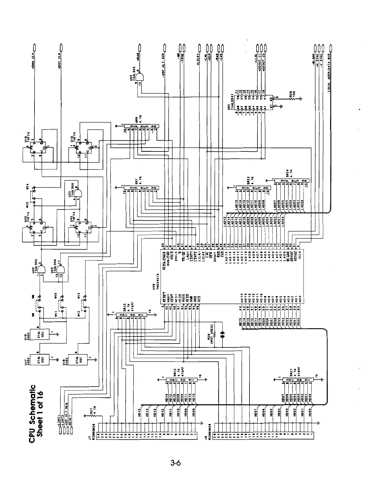
CPU Schematic
Sheet 3 of 16 REE
sas. REeeE
=I ‘YWRAMCTL | _a] rl al = : EEEEEGE!
E g FT] uaa woever EEEE!
aaa
Th VIIa 1D Tree WATT VIFF yy 100 otk, crt
U27=Hyy 100, #SCUK-cox
‘ 91 JO y Je0us
oWDWeYDS Ndd ee para 7 or
PROGRAM HEWORY
CPU Schematic
Sheet 5 of 16 LOCAL _ADOR BUS LOCAL_DATA BUS
“Ay ae
= SEL LOCAL_ADDR/DATA BUS ura TaALss74 tae
JAAS + ~cOIN. CNTAI
osRESEL sae +
+11 vee CPU Schematic Wassre
Sheet 6 of 16 has i ait = ona Bar VIDEo DATA BUS.
LOCAL_DATA BUS
CPU Schematic
Sheet 7 of 16 cytno wut, co CoEScAL ADDR ous IMAGE DATA BUS,
Siw | usa YIROMCTL
This page reads as a drawing: its text was drawn rather than typeset, and comes out in fragments. See the original scan.
This page reads as a drawing: its text was drawn rather than typeset, and comes out in fragments. See the original scan.
This page reads as a drawing: its text was drawn rather than typeset, and comes out in fragments. See the original scan.
CPU Schematic
Sheet 11 of 16
] IROE. COX © § 8% SERIAL DATA BUS.
WI We Fe THE awe Wa 108 9LIOZL FooUs our QYOWSYSS Ndd THE aoa 5 amare 2 ¢ oot oS
CPU Schematic
Sheet 13 of 16 ve vr Tam.ss74 Taass7s. ves TeaLss7s
DEN ODoUT. ct
CPU Schematic
Sheet 14 of 16
=H SYNC COLOR DATA BUS COLOR ADDR BUS ED. GUN ‘ERX, GUN
an {NOT USED)
caw oor vay safe
ron a7 R20, vat site {hor _useD)
yor yar 22 a va “
3-20
cote. In : CPU Schematic ets =i Sheet 160f 16 * vans | ft
COIN. cr EE sletzlel * Liu
A U
TROG CABINET WIRING -
E
Zeavanhon= hone
‘SEE CONTROL PANEL WIRING. REFERENCE “AY
SEE CONTROL PANEL WIRING
REFERENCE “8° paseo VaGson=
SQINDOOR SERVICE SWITCH WHT-RED_ (COIN COUNTER 1_WHT- ORG! CON WHT-BLU ‘SEE CONTROL PANEL WIRING REFERENCE °C” it PEELE ‘GROUND GAN-BAN |l19 Tag vac. See 2 -—_! COIN DOOR LIGHT CPU
Cable pin: H- 19554 [AMA EDGE CONNEC!
SPEAKER
Cable pm: H- 13213 SWITCHER POWER ‘SUPPLY
3-22
TROG CONTROL PANEL WIRING
SPIKE |3
REFERENCE "A" | ¢
GWEN | 8
| Po | BLU-ORG | RIGHT MOV |
| "1 | BLU-YEL | 4 PUNCH |
| 12 | VIO-ORG | ‘3 START |
| to | |—_VIO-VEL. | 4 START |
14 N
| 1 | YEL-BLK | UP MOVE | H |
| 2} | YELBRN | 2 DOWN MOVE | 4 |
K KEY
| 4 | :RED | 2 LEFT MOVE | : |
| 5 | YEL-ORG | RIGHT MOVE |
RN START REFERENCE "B" | § [vera DSTART
| 8 | M40 | 2 PUNCH |
BLoop |s |—S¢— jo|—-No 41{—NG 42| NC
| 1 | ORG-BLK | 4UP MO | 1 | |
| 2 | BLK | ‘GROUND. | 7 | |
| 3 | _ORN-BAN | {DOWN MOVE: | 4 | |
| 4 | [LORG-RED | FT MO | 4 |
| 5 | ORG | RIGHT MOVE. | 2 |
REFERENCE "C" | 6 | -ORG-YEL 1 PUNCH 7 {NC REX |8& | KEY ee — [12}-Ne
3-23
POWER WIRING DIAGRAM ON/OFF BACK DOOR Cable pin: H- 19555 SWITCH
TRANSFORMER CHART _ To UGHT FIXTURE, > 6OHZ = SOHZ To POWER SUPPLY
To MONITOR
FROM POWER SWITCHES 15 PIN CONNECTOR 4 PIN CONNECTOR
| YEL | 3 | > | WHT. | FY |
WHT gO. 2 | 120V ISOLATED FOR ° 2A MONITOR AND POWER lela 403 : SUPPLY OTE: . 7 SunpeneD | SEE ai a 3 VOLTAGE = nm 4103.5 es 1
| art VOLT | SELECTION | 4 | a | ae | 115 | YEL = WHT | S.9V FOR COIN DOOR |
| Ose taTION | TABLE | 6 | = | UGHTS |
XFMR 5610 - 12559 - 00 2PIN
| 10 | BLC | + | CONNECTOR |
vty
TOPOWER .WHT-RED SWITCHES —BLK= YEL 2 —WHI.RED. FROM LINE vy 7 BLK HEL FILTER
Voltage Selection Table
Py 103.5 5-6,7-8, 10-9 415, 5-67-11, 10-1: 132, §-6,7- 14, 10-15 207, §-9,19-8 2185 $:9,10-17
3-24
TROG INTERBOARD WIRING
To Contro! Pana! Connector
dj JAMMA Edge Connector see i : JAMMA CHART diddgasded [sete] 1 F_[Fresaseve] [irzsesereewn a] ne FromAudo Power to Audio “ Board J5 Board J3 Ne 5 2 —more=| Y-UNIT CPU BOARD Saoorg" |e & TBLU-RED]] © | > iq xausm?| mes) 3 NC :
J9A JOB From J4 On Audio Board a
Not Used a Not Used
a z
| 4 | s | = | |_|Reo | zi | |
| 3 | _vio | RIBBON CABLE | Power From | nL | [Bix |
| & ache | TOCPU | ‘CPU | &] © [_[Ne |
3 —aclls Jus » | AsHete g aay" vg oe AUDIO BOARD ag pe ae s)o Ciuc ¢ a [Tek &
3-25
Conirol Panel Wire Colors
Rex Up Orange-Black
Down Orange-Brown
Left Orange-Red
Right Orange
Start Button Yellow-Green Punch Button Orange-Yellow
Ground Black
Bloop Down Yellow-Brown
Up Yellow-Black
Left Yellow-Red
Right Yellow-Orange Start Button Yellow-Blue Punch Button Yellow-Violet
Spike Up Red-Black Down Red-Brown Left Red-Orange Right Red-Yellow Start Button Violet-Orange Punch Button Red-Green
Gwen Up Blue-Black Down Blue-Brown, Left Blue-Red Right Blue-Orange Start Button Violet-Yellow Punch Button Blue-Yellow
3-26
WARNINGS & NOTICES
Waming USE OF NON-MIDWAY PARTS OR CIRCUIT MODIFICATIONS MAY CAUSE SERIOUS INJURY OR EQUIPMENT DAMAGEI USE ONLY MIDWAY AUTHORIZED PARTS.
- For safety and rellablility, substitute parts and modifications are not recommended.
- Substitute parts or modifications may void FCC type acceptance.
- This game ls protected by federal copyright, trademark and patent laws. Unauthorized modificatlons may be Illegal under Federal law. This also applies to Midway logos, designs, publications and assemblies. Moreover, facsimiles of Midway equipment (or any feature thereof) may be illegal underfederallaw, regardless of whether ornotsuch facsimiles are manufactured with Midway components.
Notice No part of this publication may be reproduced by any mechanical , photographic, or electronic process, or In the form of a phonographic recording, nor may be transmitted, or otherwise copied for public or private use, without permission from the publisher.
COPYRIGHT 1990 MIDWAY MANUFACTURING COMPANY ALL RIGHTS RESERVED
MIDWAY MANUFACTURING COMPANY
3401 N. CALIFORNIA AVE. CHICAGO, ILLINOIS 60618