Oscar Conversion Kit Instructions (780-0082-00)
Psycho-Nics Oscar (World revision 0) (Data East Corporation, 1987) · Kit Instructions · 30 pages · 17 sections · original scan
Oscar”
COMVERSIOM KIT
INSTALLATION INSTRUCTIONS
470 Teta Ea San J 95112
PN780-0082-00
FCC WARNING
This equipment generates and uses radio
manual, may cause harmful interference to
radio ions. This equipment has been tested and found
to comply with the limits for Class A are designed to provide reasonable protec’
pursuant to Subpart J of Part 15
interference when the equipment is operat
environment. Operation of this equipment in a residential environment is likely to cause interference in which case the user, at his own expense, will be required to take whatever measures are necessary to correct the interference.
FBI WARNING Federal law provides severe civil and criminal penalties for copyrighted audiovisual works and video games. The Federal Bureau of Investigation investigates allegations of criminal copyright infringement.
Oscar7™M is Copyright 1987 Data East Corporation, sold exclusively in the United States of America and Canada by Data East USA, Inc. All rights reserved.
To obtain replacement parts or technical assistance, contact the authorized Data East distributor in your area. If you require referral or further technical assistance, East's Customer Service department during to 5:00 pm Pacific Time at (408) 286-7074.
OSCARTM
INSTALLATION & SERVICE MANUAL
TABLE OF CONTENTS
+ Warranty Information... ccccceueceeeeerees GENERAL INFORMATION
Specific RequirementSscccssccsveevevcvevcssteeeesersseed
+ List of Materials.ssccccccecccccccccaceceenecucveseseane 1
Installation Instructions. .sscceceeseseeeverseeneeeseee rd
GAME INFORMATION
+ Game Options... eccecccsececsevcesenesereeeeeesesesecero ld
TECHNICAL INFORMATION
PCB Edge Connector Pin-Out......eeeee
PCB Layout Diagram. cee veces verccvceveeeeeneeesseee ee eD
Component List..ccececeeceeceeee Se eee
Schematic DiagramsS....sseccsecceecccceeercsseseeseeecedd
©1966 DATA EAST USA, INC. 470 NEEDLES DRIVE SAN JOSE, CA. 95112 (408) 286-7074
FIRST PRINTING JANUARY 1988
PN: 780-0082-00
| 1. GENERAL INFORMATION |
A. Specific Requirements.
The Oscar™\ video game is a one or two player video game conversion kit. It is intended to be installed into an existing video game cabinet and comes with all the necessary components to make the converted game lock and play like a new dedicated game!
The game to be converted must meet the following requirements:
MONITOR: Horizontal, RGB, negative Composite Sync input.
POWER SUPPLY: + 5 vde @ 5 amperes, and + 12 vde @ 1 ampere (minimum)
List of Materials. |
| QTy | DESCRIPTION | PART NUMBER |
| 1 | PCB, OSCAR | 510-0122-00 |
| 1 | MAIN HARNESS, JAMMA, KIT | 036-0158-01 |
| 1 | JOYSTICK, 4/8 WAY, MONROE | 450-0009-00 |
| 6 | PUSHBUTTON ASSY, YELLOW | 350-0016-04 |
| 1 | CONTROL PANEL OVERLAY, GENERIC | 800-0030-00 |
| 1 | UNDERLAY CARD, OSCAR | 810-0027-00 |
| 2 | SIDE DECAL, GENERIC | 820-0040-00 |
| 1 | MARQUEE PLEX, OSCAR | 830-0035-00 |
| 2 | LABEL SHEET, OSCAR | 406-0091-00 |
| 1 | FCC WARNING LABEL | 406-0003-00 |
| 1 | MANUAL, INSTALLATION & SERVICE | 780-0082-00 |
INSTALLATION & SERVICE MANUAL PAGE 1
[c. Warranty Information
Data East USA, Inc., ("Seller"), warrants only to the initial purchaser ("Buyer") of its products that the items listed below are free from defects in materia! and workmanship under normal use and service for the period specified:
[enue LOGIC PRINTED CIRCUIT BOARD(S) 30 pays|
No other parts of Seller’s products are warranted,
Warranty periods are effective from initial date of shipment from Seller to Buyer. Seller’s sole liability shall be, at its option, to repair or replace products which are returned to Seller during the warranty periods specified, provided:
- Seller is notified promptly upon discovery by Buyer that stated products are defective.
- Such products are properly packaged and then returned freight pre-paid, to Seller’s plant.
This warranty does not apply to any parts damaged during shipment and/or due to improper handling, or due to improper installation or usage, or alteration. In no event shall the Seller be Iiable for any anticipated profits, loss of profits, loss of use, accidental or consequential damages, or any other losses incurred by the customer in connection with the purchase of a Data East USA, Inc., product.
WARRANTY DISCLAIMER
EXCEPT AS SPECIFICALLY PROVIDED IN A WRITTEN CONTRACT BETWEEN SELLER AND BUYER, THERE ARE NO OTHER WARRANTIES, EXPRESSED OR IMPLIED, INCLUDING ANY IMPLIED WARRANTIES OF MERCHANTABILITY OR FITNESS FOR A _ PARTICULAR PURPOSE.
PAGE 2 INSTALLATION & SERVICE MANUAL
= Installation Instructions. |
When selecting a game to convert, make sure that the power supply, the monitor, and the coin acceptors are functional. There is nothing more frustrating than installing a conversion kit and having it not operate due to a faulty monitor or power supply. 1 know...we will all suspect that the new logic pcb is defective, right?
It is mandatory that the cabinet be wired to conform with all National and Local Electric Code requirements before the conversion is attempted, The primary section must have adequate noise filtering on the AC line to prevent unwanted conducted radio frequency interference. ‘Adequate’ is defined as a filter with both common mode and differential mode filtering and a minimum current capacity of i % amperes.
According to the FCC and other regulatory agencies, every video game must have be clearly labeled with the Name and Address of the Original Manufacturer, Date of Manufacture (or serial number), Voltage Rating, Current Rating, Suitability for indoor or outdoor use, and Madel Number. In addition, the FCC requires that after conversion, the unit must be labeled with a suitable warning stating that radio frequency interference may result from use in a residential area. An acceptable sticker is included in this kit.
IT IS THE RESPONSIBILITY OF THE PERSON PERFORMING THE INSTALLATION TO COMPLY WITH ALL LABELING REQUIREMENTS.
TAKING IT APART
Performing a few simple tasks when preparing a game to be converted can save you much time and effort when you are installing the conversion kit.
Find the wiring diagram of the game to be converted! You will need to identify the required DC power supply output wires and the monitor video and sync wires. Note the color coding of these wires or better yet, label them as to their function, This kit contains a new Main Harness, but you will need to splice it into the existing power supply and video wires,
Remove the existing game harnessing that will not be used in this conversion. NOTE: you are modifying only the secondary (DC from power supply) and 1/0 (video, speaker, and controls) section of the wiring. DO NOT MODIFY OR REMOVE THE PRIMARY AC WIRING. The primary AC wiring has been designed and built to comply with UL and FCC regulations and must not be altered.
INSTALLATION & SERVICE MANUAL PAGE 3
[: + Installation Instructions (cont.) |
Remove the game pebs. Remove all exterior decals and repaint the cabinet if necessary. Repair any cabinet damage at this point. Remove the monitor plex (or glass). If your plex has silkscreened artwork on it, you will need to strip it off, or replace the plex with a piece cut to the same size. Using the monitor plex as a template, cut the supplied underlay card to the same size as the plex. NOTE: Be certain that the opening in the underlay oard lines up with the monitor CRT,
Remove the marquee plex from the game and use it cut the supplied marquee plex down to the correct size. Remove the control panel from the game and remove all controls and graphics from it. NOTE: Save the Player Start buttons, as they are not supplied in this kit.
PUTTING IT TOGETHER
Control Panel: This is never any fun, so lets do it first and get it out of the way. Choose a button and joystick layout that fits your control panel size. Refer to figure 1 for suggested panel layouts to see what holes you will need to add or block.
Oo JOIsTICK m™ 5 ©COO°PC%F6 OPTION «=-AP FIRE FIRE SUNP ‘OPTION: fo)
O AP START wets 0 0OO°0 oO Se ars i aie
erro
Figure 4
PAGE 4 INSTALLATION & SERVICE MANUAL
Install the Control Panel Overlay by peeling off the paper backing and carefully laying the overlay down onto the panel. Smooth it out starting in the center and work your way out to the edges, removing all of the trapped air pockets. If possible, cut the edges of the overlay oversize and fold the excess under the panel. Cut out the button and joystick holes. Install the Control Function Labels found on the two sheets of labels supplied in your kit. This game uses the following labels:
1 ea. "1 PLAYER" 2 EA, "FIRE® 1 ea. "2 PLAYERS" 2 EA, "JUMP" 1 OR 2 EA. "OPTION" 1 EA, JOYSTICK PATTERN, 8 WAY
Cover the Control Panel Overlay and Control! Function labels with a clear plex to protect the overlay and labels. Install the buttons and joystick at this time. NOTE: This conversion kit does not supply the Player Start buttons. You must use the buttons removed from the control panel in an earlier step. Mount the completed contro! pane! to the cabinet.
Game PCB; Mount the game PCB to a convenient wall of the cabinet using the mounting feet and hardware supplied with the pcb.
Power Supply Wiring: Plug the Main Harness edge connector onto the game PCB’s edge connector, Separate the power supply wires and route them through the cabinet to the power supply. Try to keep the length of these wires to a minimum for best results. NOTE; Use a minimum of 2 wires EACH for the +5 Volts and the Ground |ines between the power supply and the PCB, Terminate them as required.
Player Control Wiring: Route the pushbutton and joystick wires up to their proper destinations, cut to length, and terminate as required. Refer to the Edge Connector Pin-Out for WIRE COLOR and FUNCTION info.
Monitor Wiring: The game PCB has outputs for Positive Red, Green, Blue, and Negative Composite Sync. If your monitor has separate Horizontal and Vertical sync inputs, hook the Composite sync to the negative Horizontal input. This method will work on most monitors, however some model Electrohome’s require that the Composite sync signal be hooked up to both the negative Horizonta] and Vertical inputs. Contact your distributor for more information if you are uncertain as to how to hook up the monitor wires.
INSTALLATION & SERVICE MANUAL PAGE 5
Installation Instructions (cont. )
Coin Counter: The Coin Counter(s) may be the 12 volt or 6 volt type as the PCB utilizes an open collector drive circuit. Hook one coin counter wire to the required voltage (+12v or +5v) and the other wire to the coin counter signal wire from the game PCB.
Graphics: Install the Game Instruction labels onto the Underlay Card, either in the lower portion, or on one side of the picture tube cutout. Install the Underlay Card under a clear monitor plex (or glass). Mount the new Marquee Plex, and install the Side Decals. NOTE: Install the FCC Warning label to the upper rear of the cabinet,
THE BIG TEST!
REMOVE THE MAIN HARNESS EDGE CONNECTOR FROM THE GAME PCB!
Apply power to the game. Measure the +5 volts at the edge connector and adjust to +5,15 VDC, Measure the +12 and -5 vde wire to be certain they are connected properly and are on the correct terminals. Remove power to the game.
RE-CONNECT THE MAIN HARNESS EDGE CONNECTOR!
Apply power to the game once again. The attract mode video should appear on the screen. Adjust the picture size and colors on the monitor to get the optimum appearance. Adjust the Sync and Hold controls on the monitor for a stable picture. Coin it up and give it a try! Test all the controls and sound for proper operation.
Congratulations! You have completed the installation of your new Data East conversion kit! We hope that it gives you many years of successful operation.
PAGE 6 INSTALLATION & SERVICE MANUAL
rt | 2. GAME INFORMATION |
Game Options.
The game options can be changed via 2 banks of dip-switches on the game PCB. Be certain to remove power to the game when changing settings.
DIP SWITCH 1:
2 3 4 5 6 7 8 CREDIT: OFF OFF CREDIT: ON OFF. CREDIT: OFF ON zi =2 = 3 = 1 CREDIT: ON ON : = 1 CREDIT: OFF OFF = 2 CREDIT ON OFF = 3 CREDIT: CFF ON = 1 CREDIT ON __ON DEMO FREEZE MODE 1P=STOP, 2P=CONTINUE
UPRIGHT:
ACTION i 2 3 4 5 6 7 8 NUMBER THREE: OFF OFF OF FIVE: ON OFF LIVES ONE: OFF ON INFINITE: ON ON
| LEVEL | NORMAL: | OFF OFF |
| OF | EASY: | ON OFF |
| DIFFICULTY | HARD: | OFF ON |
HARDEST: QN ON
| BONUS LIVE | 40,000PTS: | OFF OFF |
| AWARDED | 60, OOOPTS: | ON ON |
| EVERY: | 90, OO0OPTS: | OFF ON |
50,OO0OPTS ONLY: ON ON NOT USED LEAVE OFF CONTINUE YES: MODE OFF OFF
INSTALLATION & SERVICE MANUAL PAGE 7
[ =. TECHNICAL INFORMATION |
PCB Edge Connector Pi ut. [
The DE-0301 connector pin-out is shown in figure 2 below. uses a 56 pin ‘JAMMA’ standard Edge Connector, The PCB edge
| SOLDER SIDE |PIN & | PARTS SIDE | sire cour} | ||
| TL | GROUND | AL | GROUND | BK |
| GROUND | Az | GROUND ° | 3k | |
| +5 VOLTS | Aa | +5 VOLTS | RD | |
| +5 VOLTS | Aa | +5 VOLTS | RD | |
| 5 VOLTS | aS | -5 VOLTS | BL | |
| +12 VOLTS | 6 | Be | +12 VOLTS | oR | |
| BLOCKING KEY | AY | B7 | BLOCKING KEY | ||
| COLN COUNTER 2 | oc | Be | COIN COUNTER 1 | SL |
Ag Bg
| SPEAKER (-) | ALO | Bio | SPEAKER coy | | BK/¥A |
AML Bis +
| VIDEQ-GREEN | A12 | 812 | VIDEO-RED | RD | ||
| VIDEO-S¥NC | Ma | B13} | VIDEO-BLUE | BL |
| _{_senvice sw. | ats | aa GROUND 4 | BK | ||
| TILT SU, (N/A) | AIS | TEST su, | BK/GH | |
| COIN SWITCH 2 | Ais | COIN SWITCH t | GN | ||
| 2P START | AMT | SP START | AN/ UH | |
| . | 2P uP | Ale | 1P UP | YL |
| . | 2P DOWN | AIS | 1p DOWN | oN |
| ’ | 2P LEFT | 220 | AP LEFT | OR |
| . | 2? RIGHT | daa | AP RIGHT | RD |
| . | 2P FIRE Sv. | 422 | AP FIRE Sv. | \ | BL |
| . | 2p JUMP sw, | 423 § Bza ] IP JUHP Su, | vi | ||
| . | 2P OPTION SW. | A24 | B2a | 1P OPTION Su. | PK |
B25
B26
| GROUND | B27 | GRowND | BK |
| GROUND | 828 | GROUND | BK |
© USED ONLY ON 2 PLAYER GAMES Figure 2
PAGE 8 INSTALLATION & SERVICE MANUAL
[®. PCB Component Layout. |
FE F ; i ® Comm TR Ds 4 (c= er i]
a Beard rake Nave NI Sow (parare card (am Ecard
Ecol a ore roar =aanr Ctard oa fay = (cam ~ g MyM f o (| & Eoard run soon EaK4 rest nwo see000 aly inal z card wees een
eT sz187¢ BIBT ame a = | wt Coere Long (oR ay HE
ROAR road
INSTALLATION & SERVICE MANUAL PAGE 9
Component List.
The following section lists the available components on the DE-0301 PCB along with the Data East part number and the location(s) where they are used.
| TYPE | DEVICE ID | PART NUMBER PCB LOCATION |
| TTL | T74LS00 | 100-0025-00 3FH |
| TTL | 7404 | 100-0007-00 1B |
| TTL | 74LS04 | 100-0027-00 1C, 10E, 8E, SFH |
| TTL | 74LS10 | 100-0029-00 OF |
| TTL | 7ALS14 | 100-0030-00 17H |
| TTL | 74LS27 | 100-0000-00 17F |
| TTL | 74LS32 | 100-0034-00 414B, 4FH |
| TTL | 74LS74 | 100-0037-00 6B, 7B, 8D, SE, 8H, 8J, 17J |
| TTL | 74LS125 | 100-0166-00 10F |
| TTL | 74LS138 | 100-0042-00 QJ, 8F |
| TTL | 74LS139 | 100-0043-00 SHI |
| TTL | 74LS153 | 100-0045-00 17E, 18E, 19E, 20E |
| TTL | 74LS157 | 100-0046-00 11 USED - SEE PCB LAYOUT |
| TTL | 74LS163 | 100-0049-00 9D |
| TTL | 74LS166 | 100-0020-00 1D, 2D, 3D |
| TTL | 74LS174 | 100-0051-00 5D, 6D, 18J, SH |
| TTL | 74LS175 | 100-0149-00 8B |
| TTL | 74LS245 | 100-0058-00 16 USED - SEE PCB LAYOUT |
| TTL | 74LS273 | 100-0022-00 3B,5B,14B, 20D, 4D, 2E, 3E, 7E, 20K |
| TTL | 74LS367 | 100-0062-00 2C, 15K |
| TTL | 74LS373 | 100-0111-00 15B, 16B |
| TTL | 74LS374 | 100-0064-00 8K |
| TTL | 74LS669 | 100-0191-00 3C, 40 |
CUSTOM BAC-06 100-0234-00 12B CUSTOM C10707-1 100-0066-00 6HJ
| CPU | 68BO9E | 100-0189-01 12EF, 16EF |
| RAM | TMM2018-35 | 105-0035-00 15D, 16D, 19HJ, 20HJ |
| RAM | MBB464A-10 | 105-0081-00 14HI |
| RAM | MB8416A-15 | 105-0082-00 BA, SA, 7D, 13D, 6K |
LINEAR YM2203 100-0123-00 1HJ LINEAR YM3812 100-0238-00 AHS LINEAR YM3014 100-0179-00 3JK, 4JK LINEAR LM324 100-0124-00 4k LINEAR MB3730 100-0081-00 3K LINEAR PST518 110-0065-00 PSTS18 HYBRID IC RCDM-11 100-0185-00 1C3, 1C4, ICS, 1C6, IC7 HYBRID IC RCDM-15 100-0158-00 1c2 RESNET RM-C3 120-0066-00 RAQ, RAi3 XISTOR 2SD880 110-0044-00 TRi, TR2 CRYSTAL 12 MHZ 140-0003-00 Xt
PAGE 10 INSTALLATION & SERVICE MANUAL
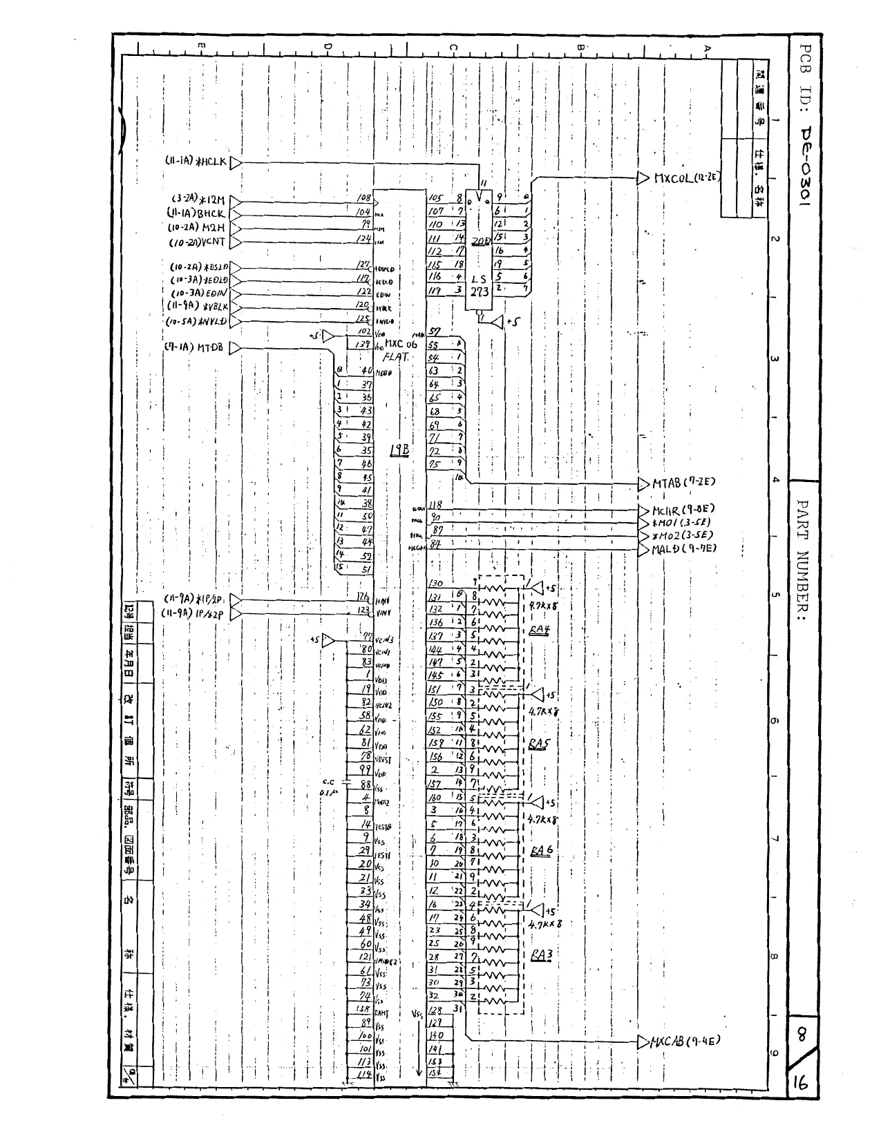
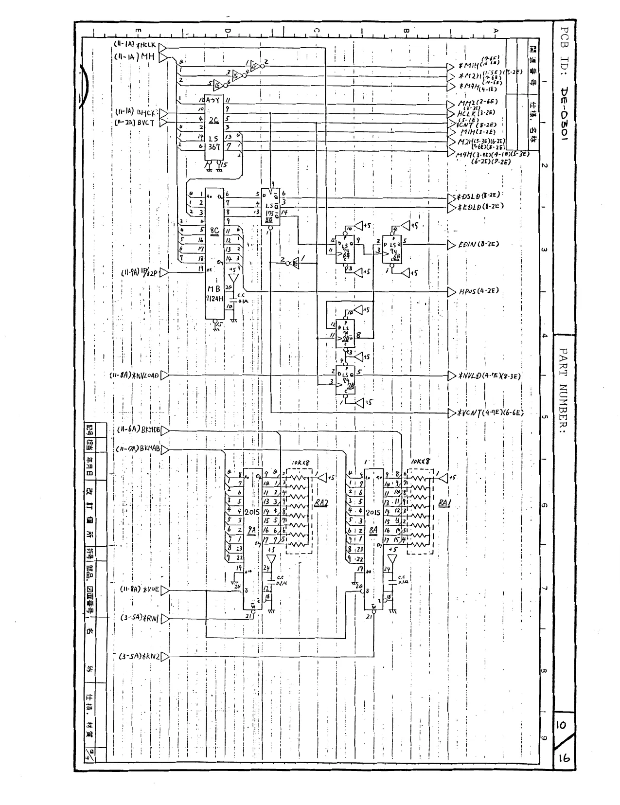
Schematic Diagrams.
DE-0301-0 PCB
Pages 1/16
thru
16/16
INSTALLATION & SERVICE MANUAL PAGE 11
G aN = ([s80o Sale ww ‘
aay, (3-34) ” i
i
i i H i
i
aemsroup
RESEND] BNKS [> K | Gan) 4BS5N[> “(2 A) 8RST [>
» GMneus.>— b nm, Mc is 6) Ls]? 7 PaRY
40285 (2-26)
H
| S280 "SS |
= fer ae ust 'dI dod efr
CPA) ¥CIRS yy
i
2-1) 1802 | i is] >
(e112 [>- Sp ]6
Co-Mbert | G3a2 [ SCpSLpE. {o> #RSTU-/E) eae 4-28) US-2E) Mes REF | loso-sa
[> crag o-46) (428) Ub-1€) (e4ED (12-28)
UadHAN LYVd
G-2A)EENWRD
Q-3ayasen|>, hele TST Saree, {> AWRT G-46 U-3E)
[> cPDB(4-5e) (6SE) Giese) (zt) U3-1E)
NAST ERMIS
(W078) jh FEED
(0-n) HOLK [> Ge Wale 2 VI Ge 2EF
[>REMWR (2-0E 101-4) AEVUR ED
o-lAean2|
CORRE H 6A URT 2A) ¢ (2 crn b> 2 QUU-SED + Q202-68)
=|; ABSEN DCI ME X29E? [> sBsen (F224)
Pp RAXL BUS-1E)
AIKEN (4-52) #BAKENGI3E) HAIXEN (5-5F) FPALEN(/2- 1)
FRW/ (4-76) SRR W2 (12- 8F) (ce Hevea (8-9 M102 D> RMCOE (9-4E)
ABKRT (13D ona (675) BAK SCE? & SOUMUH-4E) ¥COMCEL(I3-MED
{> #RPOT(I2-1E?
ATHQD (2-38) HTRCL (1-38 PUR Cr IED tIRCL2(2- 4) loeo-3a :dI ddd
T’UVd
udaHnan
SSOP ‘Sse ley] Ww i
i I i _ Ge-i)HPOS [>
¢ iz a] A 2s 24519 g G @ 73) ing [2
L> #OMST (6-85) 4S RH *USEWAN Lavd jofo-aa :di ddd
PCB ID: De&-OSel PART NUMBER:
sib EI
- A il 2." |
L
i i ‘ i ad) C-Wtese —
> » BS i ells? \ 314) 28 /| 3
3A APAL bs (i-1A) fHELK ic | io] \ U4 -6A)yPos
C4-TA) BC AD,
10-28) 2H | Go-2ayyH
Ce I
i
i
i
\ G-4A)h FKLo | Mo-mtch K
'
lc Go2A)MaH
'
3-aENWELD
{ CAA) (23s)
(aa cpa [>————
B
> bi
kb— '
fj
i i
Guiaynn [
Ge2nyi2H
'
-48) CPB
\ if
vel G-sAgHxEN >
Bf Cm Ie ola] =
B
i i
i t I i
i {
i
PS DHAD (1-36) : {> VBL (13-5£)
{> ¥0r (246) 4s HD SUdaWAN Lavd loso-3a0 :dI ddd
oe] wee RET ee |ee| yw wo li i (9-28) MoH | ceneyer7asl
(6-BAD RDM, (0-1 MI] ATOB (8-38) 4S HT 'UaaWNNN LYVd lofo-3aQa :dI ddd
This page is a drawing, shown as the original scan.
PART NUMBER:
PCB ID: DEe-o3o!
rd T512\27512] +5
72S} 12|21256| v5 7 35 2512 [2705
3 2 en eas 8 24
4324, wii Jo 23} a2 2 7.|
B) aay
ie 4 J 25127512121256) +5 2,
wal Bal Ty
KSI a; t iz
Me v7| (8 | 4 | CIrSADBKCAD [>
(U-5A) BcALo|
This page is a drawing, shown as the original scan.
> ae ‘2E | he anche a Henk [eae 'dL ddd
(8-IE) ! (WIE) (2-18)
i
i 42 HH | eR
\ozZ0-32 ott BYCT (16-28) | a t
/ 1 | GIA) yast canin | G-5A) ypakenf>:
- 3-0) 4BKRT Ci Bane-sHWRT YD - j joaereeuna)
cam 1 cay MBL { ' \ i | : | ' '
i
& {is BKCAD (7-4) UGEGWAN LYyVd
i H i
i
{> 8k (/0-5E)
i
i = |sewe ws eu] w wlio m | Bee | iat| ect
BKMAB(/8- se) pres ‘swe C2 i)! XDSPBK (12-1E) ANYLOAD (/0-SE) va #Roe (10-76)
i BCALD (4° 3€) #BCG] (1-46) 4B0G2 (4-48) YBLK (5-6E)(8-3E) 2B 1P/ap (9-2E XSIEXE- SE) 18/ 2p (4- BE ME-S 110-36)
PCB ID: D&-Oo30) PART NUMBER:
i I ! i TV-GND
- 273 fz [02
r | 174\2 61-03 3| 75 |2_5] en ies
B
2 Gl 2es\0_¢ 7) A D
g Joy) ashe Fi 4s Sane zal
sc OFBA) c-siReE>
GA) MxCoL,
GSA) pALEN Caen Cast) CLK PS
+ (5°5A) BXCoL| 6A) pspBk.
| (11-30)Bkco (200-7 PAB,
ft ik,
= [S200 2 [ee ai] 621 ai
- 'CPDB [>
COW | GOA) RPA t
Yeon? (3 1b tcoin2 | 7} SERVIC | PR} k2PSELLU | —
e
Fy g G
4} Reon |S di
15158543 i LS W245 16 4%
©] CoN CoowTER] lO€O-3BAI :GI ddd
This page reads as a drawing: its text was drawn rather than typeset, and comes out in fragments. See the original scan.
[S250 8 [so] @ wD 0 Re [ees Gx aRst | Go-uyk HOH [ (074A) popnt (A-SA) kw (4 5A) ESRD
(a-4inasas [ i
+ (saison [>—-]
LCCEEE i fe $A R
youn (4 92)
- _ “4S ‘WH
u 8 £ 9 6 S Pa XS | !WUaWAN Luvd los0-ad
S 'dI ddd
PCB ID: Deé-oBd!
PART
9] \com SL0KER/ cM
NUMBER:
| H i i / BLOKER2 i
i i
i i
i
' ‘Cou i
I el K] ObA) BLOCK
i
; [=Asl & 0 @ A laslaa, ames] & fim, HR (Z|