Wild Western
Wild Western (set 1) (Taito Corporation, 1982) · Manual · 51 pages · 14 sections · original scan
Trade Marks of Taito America Corporation
WaNnsyy, Ss owe GANiee, ge
“WILD WESTERN” UPRIGHT
TABLE OF CONTENTS
“WILD WESTERN’™ UPRIGHT GAME SET-UP ..... Page 2
A. Introduction ........--..0. 0... e cece eee eeee rere eee 2 B. Game Inspection ........ 0.0... ce cee cece eee e ene 2
C. Game Installation ....... 66.6... eee cece eee ed 2
D. Dip Switch and Volume Control Settings ...............! 2
MAINTENANCE ................. 000.00 cece eee eee 3
A. Cleaning .... 2.2.2... 66 cece eee cette etna 3 B. Fuse Replacement ................0 22. cece e eee eee 3 C. Video Monitor Removal .............-.0eeeeeee ee eeee 3 D. Video Monitor Adjustments (Separate Manual) .......... 4
E. Cover Glass Removal ...........sceeeeee ee eeeee eee es 4 F. Printed Circuit Board Replacement ...................4 4
ILLUSTRATIONS AND PART LISTS
_ Figure 1 Option Switches .............-.. 00. eee eee eee 3
Volume Control Locations ...................55 3
Fuse Replacement .............--.---.--s 200s 3
Video Monitor Removal ............ 0.000 eee 3
Cover Glass Removal . . . Printed Circuit Board Replacement .............. 4
Incandescent Panel.....-..-.-.... see eee 5 8-Way Joystick 0.0.0... eee eee eee eee 6
Control Panel .......... 6... 7
Door Assembly ..........-. 000 c cece ee eee ee eee 8
Coin Door .... --10
Coin Door .... 2.6... eee eee eee eee 12 Cabinet Assembly Upright Front View ........... 14 ILLUSTRATIONS AND PART LISTS
Cabinet Assembly Upright Rear View ........... 16
Revolving Control Assembly .................. 18
Filter Board .. 0.2.0.2... eee eee eee 20 Power Supply .......... 2... e cece eee 21
ROM Board
CPU Board ..
Video Board ............. 0.0 28
Game Board ........ 00.2.6. e cece cece 30
Power Supply Schematic 1 of 1 ..............4 33
ROM PC Board Schematic 1 of 1 .............. 34
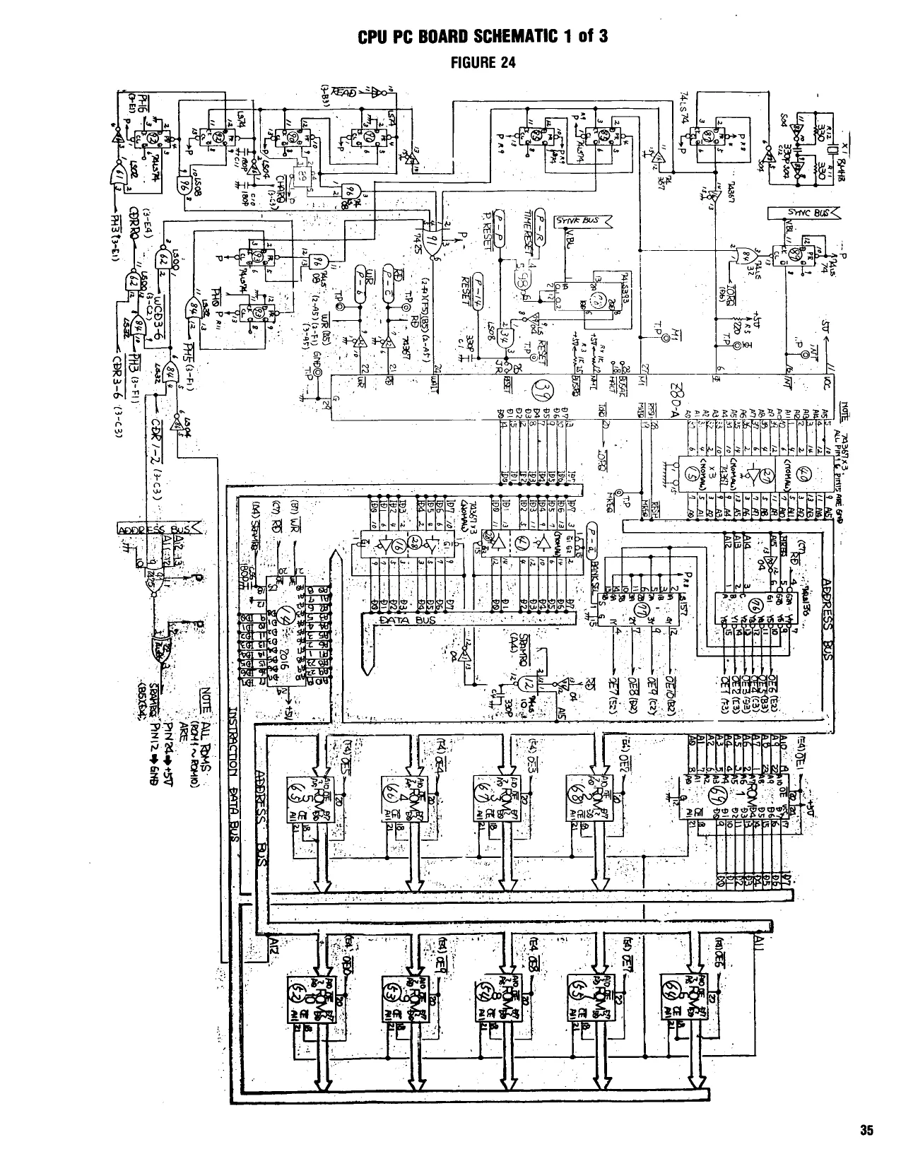
CPU PC Board Schematic 1 of 3...
CPU PC Board Schematic 2 of 3............... 36
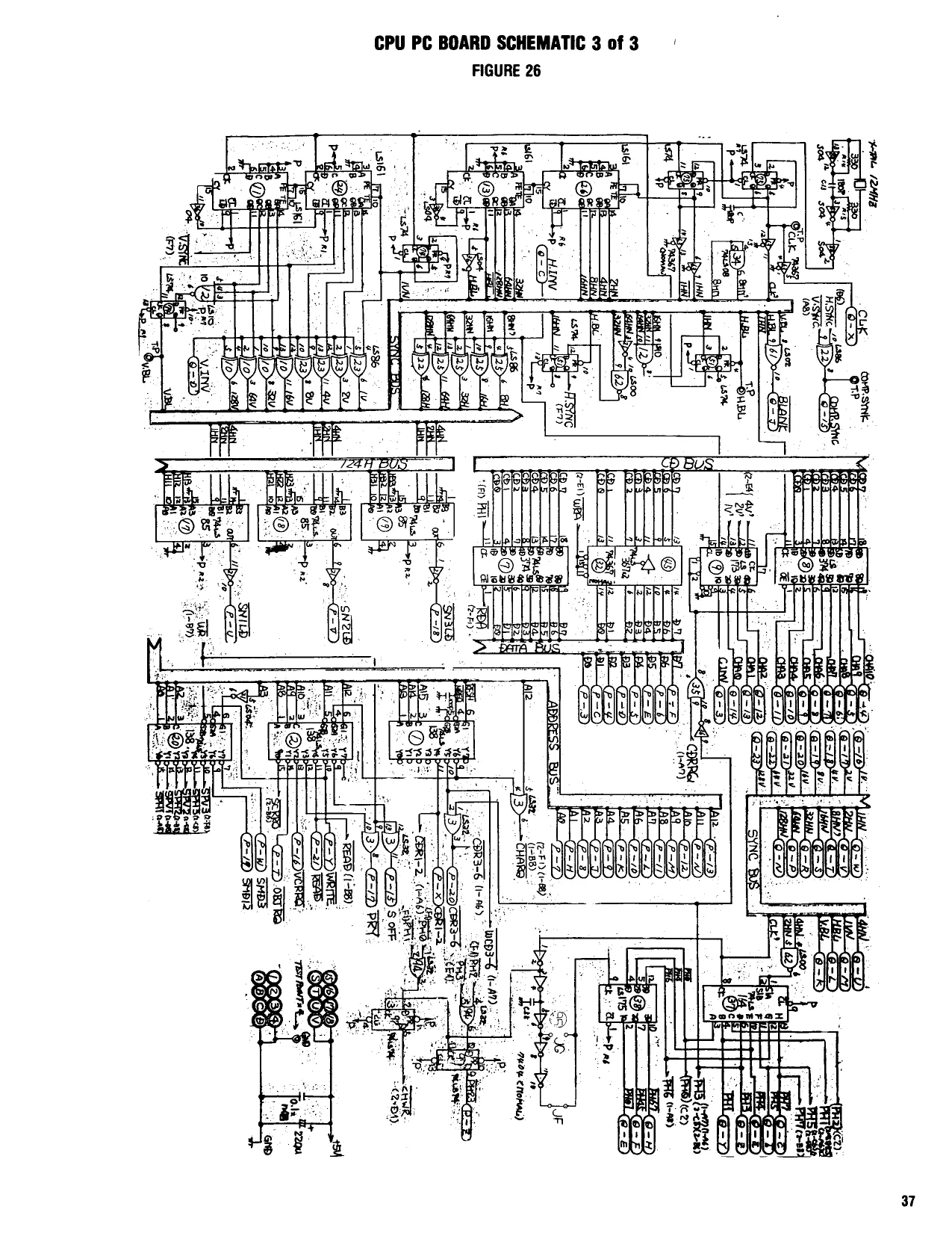
CPU PC Board Schematic 3 of 3............... 37
Video PC Board Schematic 1 of 5.............. 38
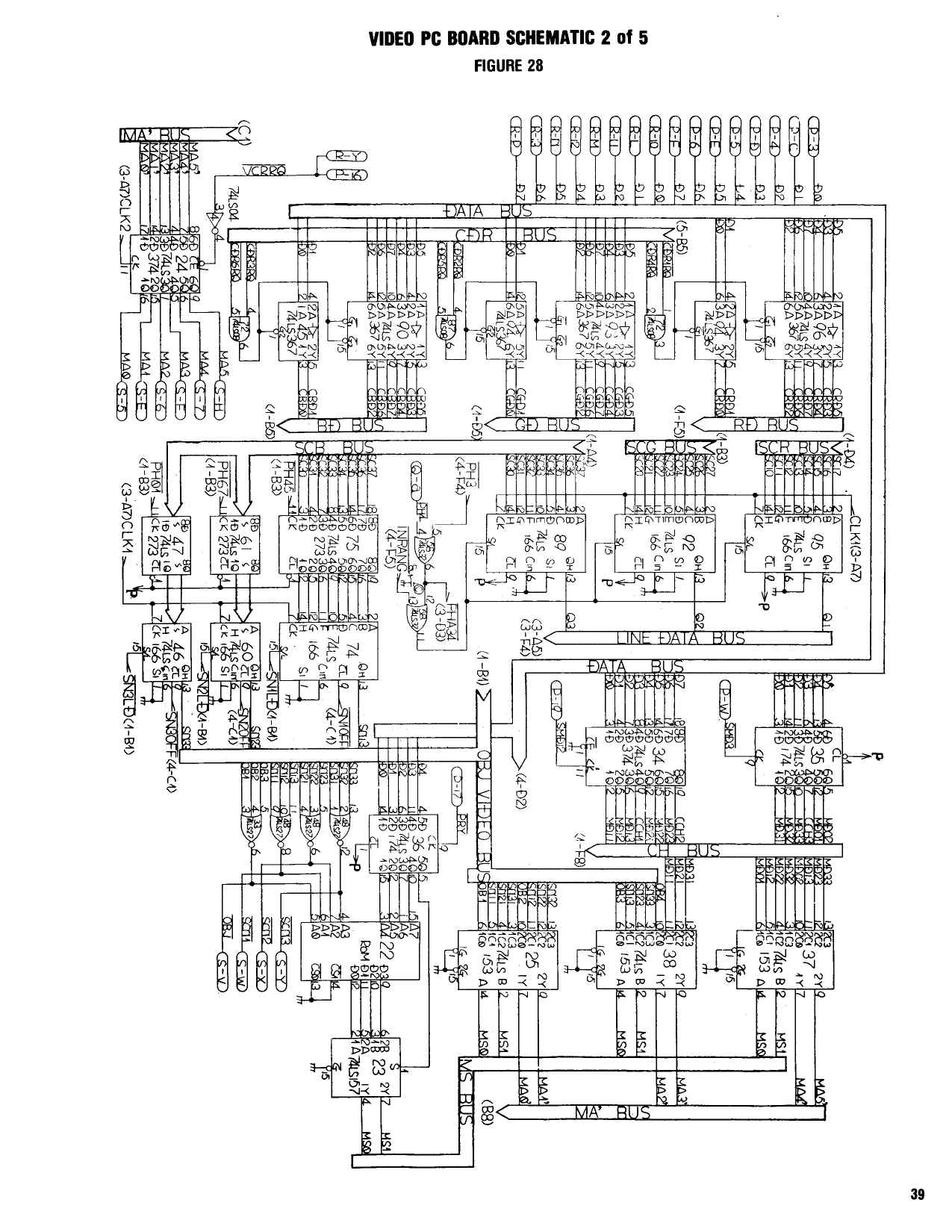
Video PC Board Schematic 2 of 5.............. 39
Video PC Board Schematic 3 of 5.............. 40
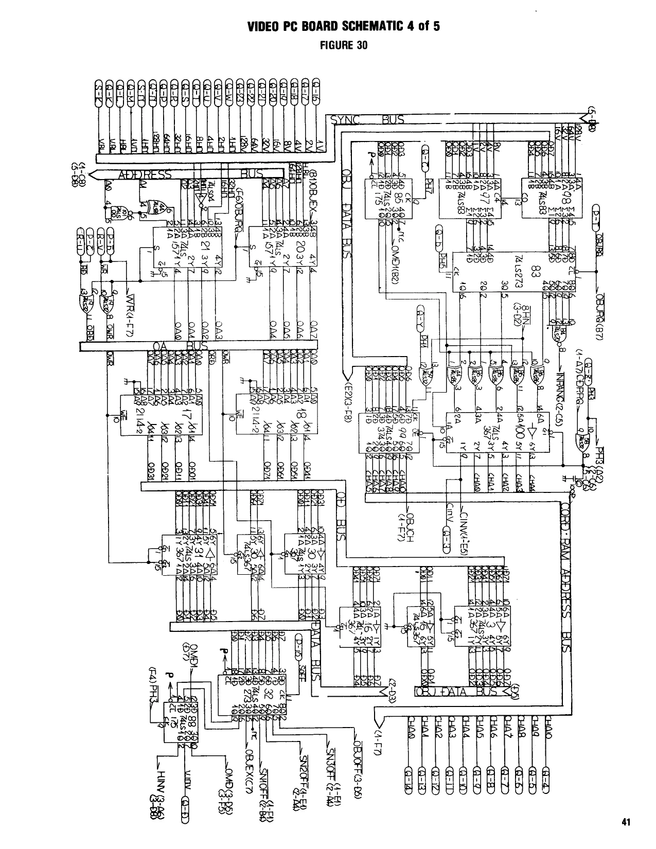
Video PC Board Schematic 4 of 5.............. 41
Video PC Board Schematic 5 of 5.............. 42
Game PC Board Schematic 1 of 7.............. 43
Game PC Board Schematic 2 of 7.............. 44
Game PC Board Schematic 3 of 7.............. 45
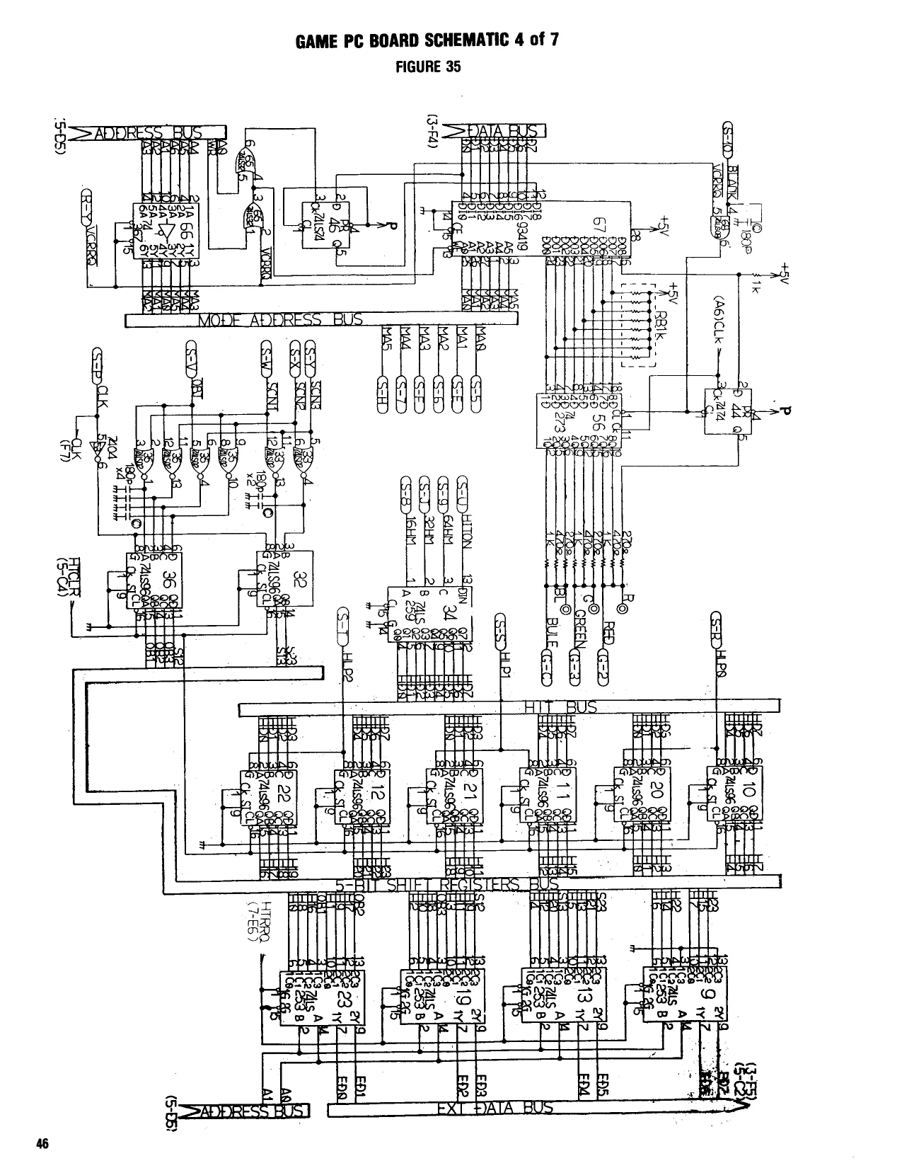
Game PC Board Schematic 4 of 7...
Game PC Board Schematic 5 of 7.............. 47
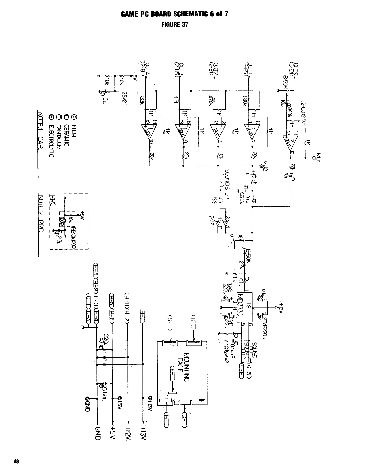
Game PC Board Schematic 6 of 7.............. 48
Game PC Board Schematic 7 of 7.............. 49
Wiring Diagram ............. 0c eee 50
72-00019-001 REVISION 1
“WILD WESTERN ”™ UPRIGHT
1, GAME SET-UP
A. INTRODUCTION “WILD WESTERN’’™ Taito America Corporation's ‘WILD WESTERN’ game is a journey back in time to the Wild West. You will mount your firey steed in pursuit of a gang of bandits and feel like a real western hero when all the bandits are shot down and the locomotive safely passes through the desert. The horses speed and direction is controlled by the 8-Way Joystick. Directional gunfire is controlled by the Revolving Control hitting the Button the player fires at the runaway bandits. The Bandits gunfire, running into cacti, rocks, or the train is fatal to the player. When a Bandit hops on the train, the player must also climb aboard in order to shoot him. Getting aboard the train requires skill and timing as he must run parallel with the train at a safe distance and push the button to get aboard. The same is true when the player returns to his horse, he must wait for his horse to run alongside the train and time his jump in order to remount his horse. Riding the train too long is also dangerous because the player must watch for outstretched waterpipes when passing by watertanks. The player must push the button to duck under the waterpipes or be knocked from the train. The Player gets a chance to improve his aim in the bonus frame hitting the coin tossed into the air by his horse. Double the Bonus for a hit, or the horse laughs when missed. The game ends when the player has lost all of his sheriffs or when 3 bandits have hopped aboard the train. An additional sheriff is added for scoring 30,000 points (adiustable) . B. GAME INSPECTION TAITO AMERICA’S CORPORATION'S ‘WILD WESTERN’’™ upright game is ready to play when received. However, careful inspection is necessary to insure your game is in perfect condition. Please verify the following before turning the game on.
- Examine external parts for chips, dents, or broken parts.
- Open the service door and examine the following:
Plug-in connectors to make sure they are firmly seated. Speaker Player Controls Printed Circuit Boards making sure there is no damage to the components.
- Check for loose foreign objects, especially metal objects which may cause electrical problems.
- Fuses, making sure they are firmly in the holders.
- Coin Mechanisms The Video Monitor is properly adjusted before shipping. If there are any adjustments mecessary refer to our Video Monitor Manual (72-00020- 001). If problems occur or technical assistance is required, contact our Customer Service Department HOT LINE Toll Free 800-323-0666 (except MMinois). Ilinois phone 312 981-1000 X215.
POWER REQUIREMENTS TAITO AMERICA CORPORATION’S ‘WILD WESTERN’’™ upright game is shipped ready for operation at 120VAC, 60Hz with a power consumption of approximately 250 Watts.
For safe operation it is recommended the cabinet be grounded. This game is equipped with a three conductor power cable. The third conductor is the ground conductor and when the cable is plugged into an appropriate receptable, the game is grounded. The offset pin on the power cable’s three-prong connector is the ground connection. LOCATION SPACE REQUIREMENTS
Depth - 35” (87.5cm) Width - 24” (61cm) Height - 68” (171cm) Weight - 300 Ibs. (Packaged Weight)
C. GAME INSTALLATION
The following precautions should be followed when installing the game.
Avoid rough handling of the game, the picture tube is fragile.
- Install the game on a level surface.
- Avoid installing the game where it may receive excessive sunlight or heat, to prevent the game from rising internal temperature. Do not install in a damp or dusty location.
- For a short time after connecting the power to the game, the picture may be temporarily distorted.
D. DIP SWITCH AND VOLUME CONTROL SETTINGS
Dip Switch A [sering | _posmion | + | 2] 3 | Points For —|__79,000_[on[on| |
Adding a a OFF] ON
30,000 OFF} | 10,000 [OFF [OFF Hi-Score Name | [oNF | Registration INo Name Reg.| 6 [| | p 5 | | 4
Test Switch | Normal | ‘Screen Inversiot [fon] | | 2p side [ [ fT ft fT for | pf | tf =fon] [| [ |
rere [on or [or [ox] 1C
1C
Dip Switch C B. FUSE REPLACEMENT This game contains 8 fuses. Seven of these fuses can be found on the Power Supply Assembly, five (5) are on the PCB and two (2) are on the Power Supply Bracket. One (1) is located at the bracket where the AC line cord comes into the cabinet. See Figure ( ) for location of these fuses. [Bistay — || No Hits are [No Hit | ty Pe |r —[— Leway—[—|
OPTION SWITCHES FUSE REPLACEMENT
C. VIDEO MONITOR REMOVAL
If you need to remove the Video Monitor, foltow the Instructions listed below.
VOLUME CONTROL LOCATIONS CAUTION
FIGURE 2 It is recommended the game be left disconnected for at least one hour before removing the Video Monitor. This will probably discharge the Video Tube but EXTREME
Disconnect power from the line voltage. Disconnect the Monitor cable connector. Remove the wire cable clamp. Take out the two side bolts, one on each side of the cabinet. Remove the four mounting bolts and disconnect the green ground wire. Slide the Monitor out by pulling the Monitor toward you.
VOLUME CONTROL SETTING CAUTION The Volume increases by turning the potentiometer as indicated in Figure 2. The Volume Control is located on the game near the (H) connector. Use extreme caution and do not touch electrical parts of the Monitor Yoke area with your hands or with any metal object in your hands! High voltages may exist in any
- MAINTENANCE Monitor, even with power disconnected.
Al! games require a certain amount of maintenance to keep them in good condition. A periodic check of mechanical controls would be beneficial to guarantee your game will be profitable. MONITOR REMOVAL
A. CLEANING The exterior of the game, all metal parts and all plastic parts can be cleaned with an non-abrasive cleanser. Caution should be used when cleaning the plastic, a dry cloth can cause scratches and result in a foggy appearance.
D. VIDEO MONITOR ADJUSTMENTS
TAITO AMERICA CORPORATION presently uses either a Wells-Gardner or an Electrohome 19" color monitor in the “WILD WESTERN’’™ game. Refer to Monitor Manual (72-00016-001) for your specific Video Monitor. Be sure to heed all the WARNINGS AND CAUTION INSTRUCTIONS provided before repairing or replacing your Video Monitor.
£. COVER GLASS REMOVAL To remove the Cover Glass follow the Instructions listed below:
- Remove the control Panel.
- Loosen three (3) screws on the Cover Glass, front bracket.
- Open Service Door and remove the (Rear) Cover Glass Bracket.
- Slide glass out through the Service Door.
COVER GLASS REMOVAL F. PRINTED CIRCUIT BOARD REPLACEMENT :
You may wish to remove the “‘WILD WESTERN’’™ Printed Circuit Boards for servicing. Refer to Figure 6. The “WILD WESTERN” Printed Circuit Boards are located on the inside of the Rear Service Door for easy access. To remove the boards the following steps should be followed:
- Open the rear service door, the power will automatically be re-
moved by the Interlock Switch located on the inside of the door
frame. . Disconnect the connector G, H, and T from the boards. . Loosen and turn the Stop Bracket and pull the boards toward you out of the board guides. on
PRINTED CIRCUIT BOARD REPLACEMENT
INCANDESCENT PANEL
TAITO ITEM PART NO. "| DESCRIPTION 1 27-00006-001 | Lamp #47 2 26B00009-001 | Bayonet Base Socket 61D00112-001 | Marquee Lighting Plate
8-WAY JOYSTICK
TEM PART NO. OESCRIPTION 63B00031-001 | Ball & Shaft 63A00033-001 | Mask 63C00027-001 | Mounting Plate 62A00002-001 | Shock Mount Pad 63A00028-001 | Switch Plate 63A00030-001 | Actuator 61A00078-001 | ‘“L"" Ring 63C00029-001 | Switch Spacer 29B00018-001 | Leaf Switch 63A00029-001 | Spacer 59B00020-017 | ‘“E” Ring
CONTROL PANEL
TAITO - ITEM PART NO. DESCRIPTION 1 63B00031-001 | Ball & Shaft 2 63B00024-001 | Push Button White 3 42B00108-001 | Cleat Wood 4 63D00032-006 | 8-Way Control 5 07-00136-001 | Control Assy., Revolving 6 42B00132-001 | Standoff Control Assembly 7 61A00015-001 | Strike Hook 8 42000017-001 | Control Panel Wood 9 07M00135-001) Control Panel, Metal 10 63D00086-001 | Lexan Decal 11 63-00025-001 | Switch Support 12 54A07001-008 | Nut, Stamped 5-11 13 29B00020-001 | Switch, Push Button
DOOR ASSEMBLY
TAITO
| ITEM | PART NO. | DESCRIPTION | REFERENCE |
1 61A00111-001 | Bracket, Lock Rod
| 2 | 08-00036-002 | Game P.C.B. | AAO 17808 |
| 3 | 08-00036-003 | CPU P.C.B. | AAO 17809 |
| 4 | 08-00036-004 | Video P.C.B. | AAO 17810 |
| 5 | 08-00028-005 | ROM P.C.B. | AAO 17811 |
6 08-00017-001 | Filter P.C.B. 7 07C00131-001 | Bracket P.C. Board 8 61A00014-001 | ‘‘L” Bracket
DOOR ASSEMBLY
TAITO -
| ITEM | PART NO. | DESCRIPTION | REFERENCE |
| 1 | 07-00027-001 | Inner Panel With Levers Sub Assembly | 404429 | |
| 2 | 54-03013-001 | Nut #8-32 | 400-8 |
09-00017-001 | Custom Harness Assembly (SHL Coin)
- 09-00017-002 | Custom Harness Assembly (Dual Coin) 61B00113-001} Service Switch Bracket 29-00022-001 | Service Switch 54-03011-001 | Nut #4-40 63-00014-001 | Switch Cover 904762 51-02052-001 | Screw #6-32 x */1e SS ph 100-63 23-00001-001 | C.R.E.M. Coil Assembly 404354 51-02052-001 | Screw #6-32 x °/16 SS ph 400-4-12 59-00019-001 | Retainer 900651 28-00029-001 | Silver Switch Wire for U.S. 25¢ 904710-1 29-00007-001 | Switch 904845 61-00044-001 | Coin Chute 904701 61-00045-001 | Coin Return Box 904598 61-00025-001 | Switch & C.R.E.M. Coil Bracket 404428 59-00018-001 | 25¢ Acceptor 5301-10 51-02051-006 | Screw 4-40 x % SS ph 110-4-6 27-00003-001 | Miniature Bayonet Base Lamp 904717 26-00006-001 | Lamp Socket 27-00003-001 | #47 Lamp (6.3 Volt) 904716 61-00048-001 | Coin Inlet Chute 904418 61-00047-001 | Right Half of Coin Inlet Chute 904594 54-00001-001 | ‘‘U'' Type Fastener 904712 51-02051-006 | Screw 4-40 x Ye SS ph 116-4-8 Slam Switch Assembly 904704 29-00006-001 998325 Coin Meters
*ltem not shown on drawing.
COIN DOOR
TAITO
| TEM | PART NO. | DESCRIPTION | REFERENCE |
| 1 | 61-00042-001 | Coin Door Only (2 Coin) | 404341 | |
| 2 | 07-00023-001 | Coin Return Button Assembly For U.S. 25* Coin | 404348-1 | |
| 3 | 63-00015-001 | Coin Return Button | | 904591 | |
| 4 | 79-50004-001 | U.S. 25¢ Price Decal | 904703 |
5 63-00016-001 | Coin Return Button Cover for U.S. 25¢ Coin
| 6 | 07-00025-001 | Lock Assembly | 904707-1 |
| 6A | 07-00025-001 | Lock Assembly | 904707-1 |
| 7 | 51-01051-003 | Screw #4 x */16 SL ph Type B | 345-4-5 |
| 7A | 51-01051-003 | Screw #4 x */:6 SL ph Type B | 345-4-5 |
| 8 | 63-00011-001 | Coin Button Housing | 904588 |
| 9 | 51-02051-002 | Screw #4-40 x % SL ph | 325-4-4 |
| 10 | 63-00012-001 | Coin Return Bezel | 904590 |
| 11 | 63-00013-001 | Coin Return Cover | 904599 |
| [a2 | 61-00040-001 | Coin Door Frame 115% x 13% | 904581 |
Mounts in a 10% x 12?/:6 Opening
| 13 | 54-01005-001 | Hex Nut %4-20 | 406-416 |
| 14 | 51A03003-113 | Carriage Bolt | 904734 |
| 15 | 07-00026-001 | Lock Arm Assembly | 404357 |
COIN DOOR
- OE Fs LS Ti. \ SB j ras ===
CABINET ASSEMBLY FRONT VIEW
TAITO PART NO. DESCRIPTION 07M00055-002 Incandescent Panel 63B00006-003 “U" Channel Bracket 47D00012-008 Marquee 61000115-001 Marquee Retaining Bracket 61D00012-001 Lower Coverglass Bracket 07-00132-001 Control Panel Assembly 07-00050-001 Coin Door 61B00113-001 Switch Bracket 07-00118-001 Service Switch Assembly 29-00022-001 Slide, Center Return Switch 29800015-001 Interlock Switch 61B00114-001 Interlock Switch Bracket
59-00008-001 Latching Clamp 63B00002-004 “T" Molding 29A00023-001 Power ON/OFF Switch
41-00015-003 Finished Cabinet
CABINET ASSEMBLY FRONT VIEW
CABINET ASSEMBLY REAR VIEW
TAITO PART NO. DESCRIPTION 1 07-00083-001 2 61B00038-001 | Speaker Grill 3 41D00015-003 | Finished Cabinet [4 63C00005-004 |(L) Molding | 5 07M00042-001 | A/C Line Cord Assembly 6 63C00005-002 {Lock Kit t 7 61B00030-002 | Interlock Bracket 8 29B00015-001 |interlock Switch 9 07M00039-001 | Power Supply 10 61000054-001 |Cash Box Lid 11 61D00060-001 |Cash Box 12 07M00054-001 |Cash Tray Assembly 13 63R00010-001 |Cash Tray (only)
| 14 | 63-00019-001 | |Cash Tray Separator |
15 61B00039-001 |Cash Tray Handle 16 42C00013-001 | Monitor Support Cleat 17 61D00208-001 |Monitor M.T.G
| 18 | 31-00011-001 | |19” Color Monitor |
| 19 | 26-00010-001 | {Socket Lamp Clip-on Mini-Bay |
| 20 | 27-00006-001 | |#47 Bulb |
21 47M00013-008 |Coverglass 22 63C00035-001 |Monitor Shroud 23 61C00006-001 |Upper Cover Glass Bracket 24 61-000142-001 jLock Rod Assembly 25 04-00037-002 |Lock Assembly 44-00001-001 |Wheel Assembly 42-00134-001 |Back Door +
CABINET ASSEMBLY REAR VIEW
REVOLVING CONTROL ASSEMBLY (WWKO00003)
TAITO Tem | PARTNO. _| DESCRIPTION 1 99-WWw090002 | Knob 2 99-WW020006 | Roll Pin 3 99-AA019609 | Plastic Washer 4 Pan Hd. Screw M4 x 14 5 99-WW020004 | %” Steel Ball 6 99-WW050002 | Spring 7 99-WW020003 | Spring Guide 8 99-AA012510_| Spacer 9 99-WW020005 | Adjust Pipe 10 99-wWw050001 | Spring 11 99-WW020002 | Parallel Key 12 99-ww040002 | CAM 13 Plain Washer 14 99-AA013658 | Tap Plate 15 Flange Nut M4 16 99-WW030002 | Base Bracket ‘‘B’’ 7 99-AA013658 | Tap Plate 18 99-AA019504 | Insulator 19 | 99-AA052532_ | Micro Switch V10FL22-1C28 20 Bind Hd. Screw M 3x 16 21 99-AA019504 | Insulator 22 99-AA052531 | Micro Switch 23 Bind Hd. Screw M3 x 16 24 Pan Hd. Screw M4 x 6 25 Lock Washer 4M 26 99-WW030003} M.S. Base 27 99-WWw040001 | Gear 28 Plain Washer 9.5 dia x 15 dia x 1.6 thick 29 Screw M4 x 6 30 é Spring Washer 4M 31 61A-00244-001) Inlay Knob 32 99-WW030001| Base Bracket ‘‘A’’
REVOLVING CONTROL ASSEMBLY (WWKO00003)
ITEM FILTER BOARD
Cap, 470pf + 10% Axial Lead Ferrite Bead Assembly
Transistor NPN 2N3904 Resistor 1K ohm YW Resistor 3.3F ohm %W wl} ola} a|olrm|
er er an)
ZA ZA
ik: Coccqoo0 CCD | 000 OCC0N00000 00
sia COO C0 Oe CO
QooceecoonnnD 00.0.0 CoD 000 1A iy
- 000 000s OOOO 900 Ob CONN, 5 PIN
e Ne Ga Sg
FERRITE BEADS
TRANSISTOR Cyn
RESISTOR RESISTOR
CONN 14P
"APACITOR
RESISTOR
100 90000 z¢ ay
POWER SUPPLY
TAITO | TAITO SYM | PART NO. DESCRIPTION SYM | PART NO. DESCRIPTION
| Ri | | 11-00001-102 | Resistor 1.0K 5% %W 5% | C5 | 12-10001-102 | Capacitor, .001uf |
R2 | 11-00001-512 | Resistor 5.1K %4W 5% C6 | 12-30001-106 | Capacitor, Tantalum 10uf
| R3__| | 11-00001-183 | Resistor 18K %4W 5% | C7 | 12-20003-509 | Capacitor, Electrolytic 50,000uf |
R4 | 11-00001-224 | Resistor 220K %4W 5% C8 | 12-30001-105 | Capacitor, Tantalum 1.uf 35V R5 | 11-00001-472 | Resistor 4.7K Y4W 5% C9 | 12-20003-209 | Capacitor, Electrolytic 20,000uf R6 | 11-00001-222 | Resistor 2.2K YaW 5% C10 | 12-10001-332 | Capacitor, Ceramic .0033uf R7 | 11-10001-101 | Resistor 100 %W 5% C11 | 12-30001-476 | Capacitor, Tantalum 47uf Z|
| R8_| | 11-00001-102 | Resistor 10K %4W 5% | C12_ | 12-30001-105 | Capacitor, Tantalum 1.uf 35V | |
| R9_| | 11-00001-472 | Resistor 4.7K Y4W 5% | C13 | 12-10004-103 | Capacitor, Ceramic .01uf |
R10 | 11-10001-101 | Resistor 100 2W 5% C14 | 12-10001-102 | Capacitor, .001uf R11_ | 11-30001-015 | Resistor .15 4W 5% C15 | 12-30001-476 | Capacitor, Tantalum 47uf R12 | 11-30001-015 | Resistor .15 4W 5% C16 | 12-20002-108 | Capacitor, Electrolytic 1,000uf R13 | 11-00001-472 | Resistor 4.7K V4W 5% C17 | 12-30001-225 | Capacitor, Tantalum 2.2uf 25V R14 | 11-00001-222 | Resistor 2.2K %4W 5% C18 | 12-30001-225 | Capacitor, Tantalum 2.2uf 25V R15 | 11-00001-222 | Resistor 2.2K YW 5% C19 | 12-30001-105 | Capacitor, Tantalum 1.uf 35V
| R16 | 11-60001-252 | Pot 2.5K YW 20% | FA | 24-00003-010 | 10A Fuse |
R17 | 11-00001-222 | Resistor 2.2K “4W 5% F2 | 24-00003-010 | 10A Fuse
| R18 | 11-60001-102 | Pot 1.0K %W 20% | F3 | 24-00003-003 |Fuse, 2A |
| R19 | 11-00001-511 | Resistor 510 %W 5% | F4 | 24-00003-004 |Fuse, 4A |
R20 | 11-10001-470 | Resistor 47 YaW 5% F5 | 24-00003-004 |Fuse, 4A
| R21 | 11-00001-162 | Resistor 1.6K YW 5% | BR1_| | 13-00100-025 | Diode Bridge 25A, 100V |
| R22 | 11-00001-103 | Resistor 10K YW 5% | BR2 | | 0100-072 | Diode Bridge 12A, 100V |
R23 | 11-00001-472 | Resistor 4.7K YaW 34 . BR3 | 13-00100-002 | Diode Bridge 2A, 100V R24 | 11-00001-222 | Resistor 2.2K %4W 5% — D1 | 13-14002-001 | Diode IN4002 R25 | 11-60001-102 | Pot 1.0K %4W 5% D2 | 13-14002-001 | Diode IN4002 R26 | 11-00001-472 | Resistor 407K %4W 5% D3 | 13-10752-001 | Diode, Zener IN752 R27 | 11-00001-222 | Resistor 2.2K YW 5% D4 | 13-14002-001 | Diode IN4002 R28 | 11-60001-252 | Pot 2.5K %W 20% DS | 13-14002-001 | Diode IN4002 R29 | 11-00001-472 | Resistor 4.7K %4W 5% 06 4 13-14002-001 | Diode IN4002 R30 | 11-00001-122 | Resistor 1.2K %W 5% D7 _| 13-10964-001 | Diode, Zener IN964 R31 | 11-10001-470 | Resistor 47 %4W 5% D8 | 13-14002-001 | Diode IN4002
| R32_| | 11-30001-015 | Resistor .15 4W 5% | DQ | 13-14002-001 | Diode IN4002 |
R33_ | 11-00001-222 | Resistor 2.2K v4W 5% D10 | 13-14002-001 | Diode IN4002 R34 | 11-00001-122 | Resistor 1.2K Y4W 5% D11 | 13-14002-001 | Diode IN4002 R35 | 11-00001-511 | Resistor 510 %4W 5% D12 | 13-14002-001 | Diode IN4002 R36 | 11-00001-222 | Resistor 2.2K Y4W 5% LED1{ 13-00001-001 | LED (Red) R37_ | 11-00001-104 | Resistor 100K LED2| 13-00001-001 [LED (Red) R38 | 11-00001-103 | Resistor 10K YaW 5% LED3} 13-00001-001 | LED (Red) R39 | 11-00001-224 | Resistor 220L %4W 5% LED4} 13-00001-001 | LEO (Red)
| C1 | 12-30001-225 | Capacitor, Tantalum 2.2uf 25V | U1 | 15-62500-001 | Opto Coupier H11AA2 |
C2 | 12-10004-103 | Capacitor, Ceramic .O1uf U2 | 15-50556-001 | Timer (Dual) 556 C3 | 12-10004-103 | Capacitor, Ceramic .O1uf U3 | 15-50723-001 | Voltage Regulator 723
| je4 | 12-30001-105 | Capacitor, Tantalum 1.uf 35V | U4 | 15-50723-001 | Voltage Regulator 723 |
POWER SUPPLY
TAITO SYM | PART NO. DESCRIPTION REG1| 15-57912-001 | Voltage Regulator 7912 REG2} 15-57905-001 | Voltage Regulator 79L05 Q1 | 14-22905-001 | Transistor 2N2905 Q2 | 14-22905-001 | Transistor 2N2905 Q3 | 14-22905-001 | Transistor 2N2905 Q4 | 14-22905-001 | Transistor 2N2905 Q5 | 14-23055-001 | Transistor 2N3055 6 _|14-22905-001 | Transistor 2N2905 Q7 | 14-20030-001 | Transistor TIP-30A Q8 | 14-26401-001 | SCR 2N6401 Q9 | 14-26401-001 | SCR 2N6401 J1 | 25-00022-006 | Connector, 1-380999-0 6Pin J2 | 25-00022-008 | Connector, 350212-1 8Pin J3 | 25-00002-014 | Connector, 09-60-1141 14Pin J4 | 25-00002-014 | Connector, 09-60-1140 14Pin 24-10001-001 | Fuse Clips 30-00220-002 | Heat Sink Dual To-220 {__[30-00003-007 [Heat Sink Single To-3
vs
vs a
ry er POWER SUPPLY COMPONENT LAYOUT
v 100-20000-80 rn (OLIV) + ue ‘y'sin NI 30Wm a
F2 asvs fl
Ss) Bg ©
ROM BOARD
TAITO PART NO. DESCRIPTION 99-ww070004 ROM PC BOARD NOT USED
99-AA055161 CONNECTOR SOCKET HKP-30FD
99-AA055787 IC - SOCKET 24P NOT USED 99-AAT33096 LS - IC 74LS138
99-AAT36071 CMOS 40193
99-WW090408 PROM (2732) WWO8 99-ww090409 PROM (2732) WWO09 99-WW090410 PROM (2732) WW10 99-ww090411 PROM (2732) WW11 99-wwo0g0412 PROM (2732) WW12 99-WWwo09041 PROM (2732) WW13 NOT USED NOT USED NOT USED 99-AAT41244 CAP, FILM TDY-1H-104 99-AAT41430 CAP, TANTALUM SSG25-10F | 99-AAT41436 CAP, TANTALUM SSG35-1F 99-AATS1765 RES, CARBON 1 KOHM ¥%4W 5% 99-AA062637 TINNED COPPER WIRE 10 NOT USED ‘99-WWO070213]PC BOARD STICKER WWN00004
ROM BOARD COMPONENT LAYOUT
© “paawscsaassaaeg(E] 0 qd gd
st
This page reads as a drawing: its text was drawn rather than typeset, and comes out in fragments. See the original scan.
This page carries no recoverable text. It is a drawing or a photograph. See the original scan.
This page reads as a drawing: its text was drawn rather than typeset, and comes out in fragments. See the original scan.
gal = SA. BBB BE cREOBAR, ARSE ARBARAS, HpABBe -JRRBaR (lab a885 spa bbe line aauiaal SH RRBRBS Ganjag| aagaagat Sananppb onsnnnn
This page reads as a drawing: its text was drawn rather than typeset, and comes out in fragments. See the original scan.
GAME BOARD
TAITO
| ITEM | SYM | PART NO. | DESCRIPTION |
95 NOT USED
| 96 | R28 | 99-AAT51068 | |RES, CARBON 15 OHM Y4W 5% | |
| 97 | R29 | 99-AAT5S1969 | |RES, CARBON 30K OHM %4W 5% | |
| 98 | {R30 | 99-AAT51971 | |RES, CARBON 1M OHM '4W 5% |
| 99 | R31 | 99-AAT51982 | |RES, CARBON 1 OHM YW 5% | |
| 100 | |VR | 99-AAT53041_|RES, VARIABLE RESISTOR B-50K | |
| 101 | RB1 | 99-AAT55036_ | |RES, BLOCK 1K OHM 8 ELEMENTS | |
| 102 | RB2 | 99-AAT55061 | |RES, BLOCK 10K¥%00 OHM 8 |
ELEMENTS
| 109 | R32 | 99-AAT55033_| | WINDING RES 6 OHM 2W 10% | |
| 108 | |D | 99-AAT12007 | DIODE VO3C | |
| 104 | |ZD1 | 99-AAT13025 | FENNER DIODE RD4.7EC | |
| 105 | |ZD2 | 99-AAT13042_ | FENNER DIODE RD2 7FBF | |
| 106 | |ZD3 | 99-AAT13028 | |FENNER DIODE RD9A-M |
| 107_|ST | 99-EE070004 | |HARNESS STICKER |
108 NOT USED 110 |X-TAL | 99-AAQ69593 _|X-TAL .6MHz 111 [ROM 1 | 99-WwW090414| PROM (2732) WW14 112 |ROM 2 |99-WW090415|ROM WWi5 113 [ROM 3 99-WW090416] ROM WW16
GAME BOARD COMPONENT LAYOUT
POWER SUPPLY SCHEMATIC 1 of 1
a TS wim ¢ © wig £ @ ROM PC BOARD SCHEMATIC 1 of 1
This page is a drawing, shown as the original scan.
CPU PC BOARD SCHEMATIC 2 of 3
EE 2/2 = 10
This page is a drawing, shown as the original scan.
DA) D4) ~B-A7)ICLK1>_, PHE7@-A6) g 3 aga FER dg 3 Rranenes JBAaRAaQABS 12 JUNdId S JO | OLLVINSHOS GUVOd Id O30IA
This page is a drawing, shown as the original scan.
VIDEO PC BOARD SCHEMATIC 3 of 5
pla JAE DIO
foc las 44 a Ad. OE pee :
This page is a drawing, shown as the original scan.
en) > Bo, Oa DULATOLLITN WAWLUOL INVAID wid Tr amoev-e) BPEVHd(Z9-€,
‘GOLIH (EV-€) VIDEO PC BOARD SCHEMATIC 5 of 5
GAME PC BOARD SCHEMATIC 1 of 7
GAME PC BOARD SCHEMATIC 2 of 7
. CFPAXBY) __ (2-B5)
c S10 ©O.1u 10kx3 tkx3 GAME PC BOARD SCHEMATIC 3 of 7
This page is a drawing, shown as the original scan.
GAME PC BOARD SCHEMATIC 5 of 7
(7-C2 COIN LOCH
AWAY OR 2WAY
(FEN)
abe Ey A i kd fs M Gi Be
EPORTT (E3)(1-B8)
This page is a drawing, shown as the original scan.
GAME PC BOARD SCHEMATIC 7 of 7
(5-A5)WR — | 9 ___- TNPUTT (3-A2) (SADRD w|i TNPUT2(3-B2) Pao. . 3 Z ~ATRAA (4-B2) AL ~4 ig EXRER =z) [A2 -—-—{ RIM js BDIR (3: D3 a 2 ta BCI 13-03 (SDS)
READIN, 3-B2;
(5-D4) EXPORT (5-6) A COIN (S-C6; BCOIN
= Hi al no I ii a sS ld - OL_lWeo |. 6Q/(S BANK SEW Rez) pps sal anc ! pas __Livap iolenad ' Be Keun pw po Niza ~_-w SOUND STIPCE-D6) Bg QZ SCLIN UK (5-8) (SFA)
P [reser (3-C2) COINSET (S-Da)
® TAITO AMERICA CORPORATION 1256 Estes Avenue, Elk Grove Village, IL 60007 Telephone (312) 981-1000 Telex 25-3290