Pig Skin Conversion Kit
Pigskin 621AD (rev 1.1K 8/01/90) (Midway, 1990) · Kit Manual · 50 pages · 48 sections · original scan
MIDWAY MANUFACTURING COMPANY
Parts Information
Installation & Operation
Game Testing & Problem Diagnosis
g ]
OPERATIONS MANUAL
16-4004-K-101 August 1990
PIGSKIN, SIX-TWENTY-ONE A.D.
(Ancient Arch Rivals on a Rampage!)
‘The rigors of day to day existence in the early part of the Seventh Century A.D. were far more severe than those most of us face today. It is no surprise then, that the era produced “Role Models” of a slightly
different sort.
Men like: Attilla DeSoiled; whose infamous “Mongrel Horde” spent much of their free time sweeping across Central Asia into the dustbins of
Eastern Europe.
Men like: Thor Akenbak; the renegade Viking whose piercing battle cry “... Loot and pillage, loot and pillage, Let's go find us an English Village...”
In the Dark Ages, the world’s wildest warriors had a word for ‘mind blowing, bone crunching, heart-stopping” excitement.....PIGSKIN !
PIGSKIN 621 A.D. is a thoroughly researched, unflaggingly faithful re-creation of those exciting, fictitious days of yore when “Good, Clean Fun” was simply known as “Fun”.
Each player directly controls one of a half-dozen hulking barbarians in a bone-crushing “battle for the ball” across a medieval countryside.
The object of the game: to inflict as much pain and suffering as possible on the opposition and carry the PIGSKIN back to your “stronghold” (your ship or castle) more times than your opponent can and thereby win the battle!
PIGSKIN.
RULES
Each player directly controls an armoured team captain" ; and indirectly controls up to 5 teammates. Each player has the following to control the character selected: F
- 149 Way Joystick
- 2 Punch Button(s) (whichever is more comfortable) : :
- 1 Pass Button
- 1 Team Attitude Adjustment Button Punch buttons allow a player to throw punches (all teammembers throw punches pressed). tt can also be used along with the pass button while on defense (press both buttons to attempt a flying tackle). The Pass button allows the player to pass or kick the ballto a teammate (passplays are shown on the screen and the player has the cholce of which one to select. Team Attitude Adjustment Buttons are used to select a style of play (get the ball, man to man, bad attitude, etc.). Players may pick up "concealed weapons" by simply running over them. Weapons are used automatically durring “grapples " Involving the Pigskin. Characters that are severely injured by 4 weapons are revived after the next goal Is scored. A “grapple” Is a savage battle for the pigskin, which fe usually won by the team with the most players involved in It. The terrain will affect a character's movement (Mud, rocks, swampy areas, etc,). Players that remember how a field Is 4 "Mapped out” may learn to use the terrain to thelr advantage. Players score points for carrying the Pigskin (1 point for every [5 seconds in the player's possession), and for scoring a goal (6 points). MPORTANT NOTICE To Receive A Free Player's Handbook including:
- Rules - Designer's Notes
- Strategies - Pigskin Product Information
- Game Tips Send a Self Addressed Stamped Envelope to: PIGSKIN P.O. BOX 1000 PLANO, IL 60545
Table of Contents
Section 1: Kit Installation, Operation & Troubleshooting SONY since scesissseinsscosssersscoecsiraneeteconecneenge sequetsvcnn sarees gr sensevrsent nseiyedeé iScbsesiensnesionransst] 4-2 Conversion Instructions 1 7
Cabinet Modifications... Control Panel Modification: Typical Control Panel Layout Installing PC Boards into a JAMMA Game Cabinet. Installing PC Boards into a NON-JAMMA Game Cabine' Installing the Volume Contro! Game Features Starting-up...... Player Corttrol: Game Operation Control Switches. Game Adjustments and
Troubleshooting.......
Section 2: Parts Information
CPU Board Layout... CPU Board Parts List... 49-way Joystick Assembly. 49-way Joystick Opto Board Lay Audio Board Layout and Parts List.
Section 3: Diagrams & Schematics
JAMMA Chart. Audio Board Schemati 49-way Joystick Opto Board Schemati CPUSchematic. Interboard Wiring. Wiring Diagram... Coin Switch & Meter Wiring. Control Panel Template Diagram.
COPY RIGHT 1890 MIDWAY MANUFACTURING ALL RIGHTS RESERVED
PIGSKIN
Game Operation & Troubleshooting
Information
Safety Notices
The following safety hints apply to allkit operators and service personnel. Specific wamings and cautions will be found throughout this manual where they apply. We recommend that you read this page, and also all of Section 1, before preparing your kit for play.
NOTICE: SALVAGED PARTS Parts salvaged from old games are required to complete your kit. These salvaged parts must operate perfectly: otherwise, the converted game cannot perform properly or safely. Aways repalr circult board malfunctions and cabinet damage before conversion Is attempted.
NOTICE: POWER SUPPLY Be sure the power supply from your old game Is capable of +5V de at 5A, -5V de at 1A and +12V at 1A. These operating voltages are necessary for your kit. Your power supply must be FCC approved.
NOTICE: MONITOR Thiskit Is not intended for use with X-Y monitors. Sultable monttors have horizontally mounted CRTs and raster electronics with Inputs for red, green and blue video, as well as separate horizontal and vertical Negative Syne inputs.
NOTICE: COIN MECHANISM Be sure to clean and lubricate your old coin mechanisms. Servicing them Is crucial fo your game's eaming potential and operation.
NOTICE: COIN METERS Coin meters are not provided with this kit. Wiring Information Is provided as a convenience to the operator.
NOTICE: SERVICING, INSTALLING Always tum your game OFF and unplug It before attempting to service or Install your kit.
PROPERLY ATTACH ALL CONNECTORS. Be sure that the connectors on each printed circult board (PCB) are properly connected. If they do notslip on easily, do not force them. Areversed connector may damage your kit and vold the warranty. All connectors are keyed to fit specific pins on each board.
1-2
Conversion Procedure
Inspection Unpack the materials from the carton and Inspect for obvious signs of damage. Use this checklist to be sure your kit Is complete... —
Part No. ttem Quantity
| () A-8550-1 | Pot & Bracket Assembly | 1 |
| () C-13246-4004-K | 68K MinI CPU Board | 1 |
| () C-13581-1 | 49-way Joystick Assy | 2 |
| () C-9214-4 | Button Assy Red | 2 |
| ()C-9214-5 | Button Assy White | 2 |
| () C-9214-6 | Button Assy Yellow | 4 |
| () D-11581-4004 | Audio Board | 1 |
| () H-8865 | Volumn Control Cable | 1 |
| ()H-12746-1 | Video Signal Cable | 1 |
| () H-12758 | Audio Board Jumper Cable | 2 |
| () H-13257 | Sound Pwr/ Spker Cable | 1 |
| ()H-13411 | JAMMA Cable | 1 |
| () H-14023 | Players 1& 2 Cable | 1 |
| () 03-8250 | Control Panel Cover | 1 |
| () 16-4004-K-101 | Manual | 1 |
| () 16-9155 | Controls Template | 1 |
| () 20-9457 | Button Holder w/Switch | 8 |
| () 13-1480-4004-K | Marquee | 1 |
| () 31-1481-4004-K | Control Panel Overlay | 1 |
| () 31-1482-4004-K | Decals | 2 |
i] () 5795-10703-24 Ribbon Cable () Assorted Hardware
Recommended Toois and Supplies () black semi-gloss paint () electric drill () electric screwdriver () grease pencil or marker () hex driver () 180 grit sandpaper or electric sander () pllers () razor knife () soldering Iron and solder () wre cutters ( black electrical tape () quick-hardening wood putty
TYPICAL CONTROL PANEL LAYOUT Cabinet Modifications
- FillIn gouges with a good quick-hardening wood putty. Sand cabinet and wipe tt clean,
- Repaint the cabinet with black semi-gloss paint (Games wood grain sides: remove the old decals and clean the glue residue from the old decd before painting). Allow paint to dry completely.
- Pencil atine roughly at the top of the old graphic, Lightly molsten the cabinet with soapy water. Apply the decal starting at the top and working down. After the decal |s In place, use a plece of the foam packaging as a squee gee andsmooth the decal down, taking care to squeeze out the air bubbles. If you miss on air bubble, pop it with razor blade or apin and bumish tt down. Allow 12 hours for the adhesive In the decals to set, Remove masking.
4, Check the PIGSKIN Kit for an FCC sticker and apply It over the existing sticker on the cabinet. When Midway ships a game, It isin compliance with FCC regulations. Your sticker Is proof. If the sticker Is missing or damager, legal repercussionsto the owneror distributor ofthe game may result. If your game kit does not contain an FCC sticker, call Midway Manufacturing immediately.
- Apply the Instructions (Card or Decals) to the CRT viewing glass.
Control Panel Modifications
1, Remove the control panel buttons and Joysticks and remove the old vinyl covering.
- Placethe template on the control panel andusettto help you design your control panel. You will need to use the Mounting Template twice, once for the left sideandonce for the right side of the control panel.
One Player « Credit Button
@) Two Player
2/ S"/ Credit Button
- Drill holes as needed for the Joysticks and buttons. Plug previous holes with wood blocks, putty, cardboard or epoxy. File the new holes smooth.
4, Carefully remove the backing on the vinyl control panel overiay. Place the overlay on top of the control panel. Prevent air bubbles from getting under the viny! overlay.
5.a) After the overlay Is on securely , use a razor knife to cut holes for the buttons and Joysticks.
- Posttion the stickers around the appropriate button . focations. Refer to the Typical Control Panel Layout diagram on the previous page for suggested button and Joystick locations. Cc) Peel the backing from the adhesive on the clear protective overlay. Position the overlay so that It covers the stickers and press it Into place. Use a razor knife to cut holes for the joystick and buttons.
- To mount the pushbuttons and button-holder/switch to the control panel, push the threaded end of the pushbutton through the control panel from the top so that the threads extend through the back of the control panel. Then, take the white plastic button holder/ switch and place It over the pushbutton threads so that the threads extend through the hole In the holder. The blade switch must point toward the back of the cabinet and face you. Secure Into place with a painut. Repeat for all of the pusbutton switches.
- The Joystick must be disassembled before mounting It to the control panel. Remove the 4 screws from the back of the slide assembly. Remove the slide assembly, the PC Board, and the stop assembly. Take off the *E' ring and the white plastic spacer. Slide the knob out of the base . Mount the base to the back of the control panel. insert the knob through the base from the front of the control panel. Replace the white plastic spacer and the “E" ring. Slip the stop assembly tf the PC Board connector must over the knob shaft so the the legs fit Into the base (do face the top of the control panel not force). Replace the PC Board component side then, set DIP Switch 8 to On. facing you; BE SURE THAT THE CONNECTOR FACES THE RIGHT SIDE OF THE CONTROL PANEL. Install the slide as~ sembly so that the holes In both slides fit over the knob shaft and replace the 4 screws.
Installing the PC Boards and Wiring intoa JAMMA Game Cabinet
tf you choose to use your own 1. JAMMA Cable and not the one providedin the kit, be sure to check theJAMMACableConnectorChart 2. to verify that It ls compatible.
(Caution) * Properly insulate any unused wires within the JAMMA Cable, especially the gray, gray-green and gray-yellow wires. This Is a fully wired JAMMA Cable. Many of the wires will not be used for this 4. kit, These wires have been Installed so that you can use this cable for future kits. Disconnect and remove the existing video board In the JAMMA Game Cabinet,
Mount the PIGSKIN video board Inside the JAMMA Game Cabinet where the old video board was located Mount the sound board next to the video board using the stand-off and screws provided.
tf you choose to use the JAMMA Cable provided with the kit, unsolder your old JAMMA cable from the speaker, Powersupply, controlpanel switches (which may already be disconnected) and coin door. Remove the cable from the game. If you are not going to use the JAMMA Cable provided with the kit, check the JAMMA Cable Connector Chart to be sure your cable is compatible. Leave your power supply chassis as Is.
Connect the JAMMA Cable to JP7 on the PIGSKIN video board. Using the JAMMA Cable Connector Chart for reference, solder the correct JAMMA Cable wires to the speaker, power supply, control panel switches and coin door.
Connect the ribbon cable from J4 on the sound board to JP1 on the video board. Be sure that the red line goes to the same pin on both boards, Connect the wire hamess
Cable from J5 (speaker), and J3 (power), on the sound
board to JP2 (sound power speaker connector) on the video board.
Connect the video signal cable from JPé on the video board to your monitor. Be sure that pin 1 on the monitor ts connected to pin 1 on the video board and so on.
- Connect the Joystick hamess from the video board to The Ribbon Cable may need to be twisted In order to connect it properly. the Joystick opto boards. The player 1 connector has red. wires and Is connected from JP4 on the video board to the opto board on the player 1 Joystick. The player 2 connector has blue wires and |s connected from JP5 on the video board to the opto board for the player 2 Joystick. The power connector has 4 wires and Is connected to JP8 on the video board.
JP3 on the video board Is not used.
Place the FBI Wamng Label on the Inside of the cabinet next to the PC boards. Be sure the label is completely visible.
Installing the PC Boards and Wiring into a NON-JAMMA Game Cabinet.
Disconnect and remove the existing video board In the game cabinet.
Mountthe PIGSKIN video boardinside the Game Cabinet where the old video board was removed. Mount the sound board next to the video boardusing the stand-offs and screws provided.
Leaving several inches of wire, cut the wires at the coin door, control panel switches (which may already be disconnected) speaker and power supply.
Connect JAMMA Cable to video board at JP7. Follow the JAMMA Cable Connector Chart and splice the wires of the JAMMA Cable to the existing wires for the coln door, power supply, speaker and control panel. Be sure all of the spliced wires are well Insulated with black electrical tape.
Connect the ribbon cable from J4 on the sound board to JPlon the video board. Be sure that the red line goes to the same pin on both boards. Connect the wire hamess cable from J5 (speaker), and J3 (power) on the sound board to JP2 (sound power speaker connector) on the video board.
Connect the video signal cable from JP6 on the video board to your monitor. Be sure that pin 1 on the monitor ls connected to pin 1 on the video board.
Connect the joystick hamess from the video board to the Joystick opto boards. The player 1 connector has red wites and Is connected from JP4 on the video board to the opto board on the player 1 joystick. The player 2 connector has blue wires and Is connected from JP5 on the video board to the opto board on the player 2 Joystick. The power connector has 4 wires and Is connected to JP8 on the video board.
JP3 on the video board, Is not connected.
Place the FBI Waming Labei on the Inside of the cabinet next to the PC boards. Be sure the label Is completely visible.
1-7 Be sure all spliced wires are well insulated with biack electricaltape.
Properly Insulate any unused wires within the JAMMA Cable, especially the gray, gray-green and gray-yellow wires, This Is a fully wired JAMMA Cable, Many of the wires will not be used for this kit, These wires have been installed so that you can use this cable for future kits.
The Ribbon Cable may need to be twisted In order to connect It properly.
Installing the Volume Control
Mount the volumn control, using screws provided, where. itls easily accessible. On top of the cash box, or on the wall near sound board are two possible locations.
The volume control cable attaches the volumecontrolto the sound board at connector J2. When viewed with the white plastic knob facing you, the shield wire should be. soldered to the right lug, the red wire should be soldered to the middie lug, andthe black wire shouldbe soldered to the left lug. Refer to Volume Control Diagram.
Volume Control Wiring Diagram Red
Black Shield
Game Rules and Features
Starting Up
Switch ON the power to the game. A "rug" pattern appears on the crt screen. The next screen shows PIGSKIN REVISION LEVEL. The game then moves to the attract mode. After the proper coinage has been inserted, the game exits the attract mode and enters play mode.
Player Controls
—= Each Credit Button allows (1 or 2) players respectively, to begin play or continue play.
f= Each Joystick enables players (1 or 2) respectively, to move their team captain.
E= Four Buttons (per player) control Team Attitude Adjustment, Punch, and Pass. See diagram below for locations.
Two Player Credit Button
: |< Team Attitude Adjustment—e= © Punch © © One Player / Credit Button ~ ©
3 <___— Move
@ <+—____—Punch
- Pass
1-9
Game Operation
PIGSKIN Is a one or two player video game that uses a color monttor. From the player's perspective, the game has two modes of operation: Ready-to-Play and Play. From the service technician's perspective, the game has an addltional mode of operation called Game Diagnostics, which contains Self-Test and Game Adjustment features.
Control Switches
{J VOLUME CONTROL POTENTIOMETER can be used to Increase or decrease the volume level of the game music and speech. For greater profits, set your game's volume level at its maximum.
EQ TEST/DIAGNOSTICS SWITCH allows you to enterinto the game's Diagnostic mode. Turn the game off. Push the Test Switch towards the left to enter the Diagnostics mode, turn the game on. To extt this mode, simply tum off the Test Switch. This ls an optional switch. Game diagnostics can be reached via the DIP Switch.
SERVICE CREDIT SWITCH Is a special feature switch that allots credit without affecting the game's coin totals. This switch Is optional, the game operates without It,
E— COIN DOOR SLAM TIT SWITCH detects any forceful vibrations against the Coin Door. This eliminates pounding for free games. This switch Is optional, the game operates without It.
1-10
Game Adjustments & Diagnostics
Starting Up
All PIGSKIN game adjustments and diagnostics are menu-driven features. Each menulists several choices that you may act upon as desired. PIGSKIN contains many menu levels (i.e., one menu selection will send the game to another menu).
Switch on the power to the game. Set DIP Switch 6 to On (or use the optional test switch, if you have installed one). The first menu you see is the main test menu. Game adjustments, bookkeeping, and diagnostics are all available from this menu.
Once in the main test menu, use the PLAYER JOYSTICK to select an option and the one or two player CREDIT BUTTON to enter into it. Notice that the selected option is always the one that has the cursor in front of it.
PIGSKIN 621
A, SELF TEST
- SWITCHES
- GRID
4, DIP SWITCH
_ §. RESET HISCORE
USE PLAYER JOYSTICK TO MOVE CURSOR & SELECT CHOICE.
PRESS 1 OR 2 PLAYER CREDIT BUTTON TO START TEST.
Main Test Menu
PIGSKIN DIAGNOSTICS & ADJUSTMENTS
SELF TEST
This test is designed to locate and identity any computer malfunctions. When selected, the game enters this mode immediately and begins scanning its memory. The phrases "PASSED TEST" or "FAILED TEST" will appear on the screen depending on whether the test was successful or not.
SWITCHES
The Switch and Sound Self-Test mode allow the operator to determine if all game switches, sound features, and the opto-board controlled joysticks are operating properly. The operator can activate switches one at a time and check the monitor screen to see if they are acknowledged.
GRID
The Convergence Grid Display Test displays a crosshatch pattern to aid in adjusting the color monitor. This pattern is useful in adjusting the color balance, convergence, vertical linearity, and vertical/horizontal sizing. To exit this test, press the Tilt switch.
DIP SWITCH
Game options are adjustable by changing the bit switch settings on the DIP Switch Table (shown on the next page). The DIP Switch unit combines seven bit switches, which are set to the ON or OFF position. When you enter this test mode, the screen shows a full display of current DIP Switch settings.
RESET HISCORE
The operator may reset the high scores by pressing both the 1 and 2 Player Credit Buttons simultaneously.
PIGSKIN DIP SWITCH TABLE
a NORMAL COIN CHUT! _ INDEPENDENT COIN _ CHUTES
ROTATE JOYSTICK (TOP)
REGULAR JOYSTIC
- After selecting this option through DIP SWITCH (3 & 4) return to the main menu and select (Coin Settings). Select the desired number of coins with the player 1(increments of 1) & player 2 Credit buttons (decremenis of 1). Foliow the same procedure for selecting the desired number of credits per coin.
** After selecting this option through DIP SWITCH (7) return to the main menu and select (Independent Coin Chutes). Select a coin chute by pressing the one or two player Credit button. Set the Coin and Credit options in the same manner as explained above.
1-13
Troubleshooting Information
Problem... No picture or distorted picture.
Tum game on and nothing happens.
No Sound.
Move Joystick , but player does not move or fire,
Press START button and nothing happens.
Put coins in and get too many credits.
Put In colns and you don't receive a credit.
Game stays In the test mode. Possible Solution... Faulty video board or monttor. Missing or disconnected video signal cable.
Check that +5V Is going to pins C, D, 3 and 4 of the JAMMA Connector. Check for the LED on the CPU Board,
Check volume control setting. Check that +12V Is going to Pins F and 6 on the JAMMA Connector. Check that -5V Is going to pins 5 & E of the JAMMA Connector. Check Interboard wiring from video board to sound board. Check the speaker and speaker connection to pins Land 10 on the JAMMA Connector.
Check for open wires between Joystick and CPU Board. Check for contamination on joystick optos and CPU Board pins. Check for proper ground.
Check for open wires between button Video Board. Check for contamination on video board pins or switch blades, Check for proper grounding on buttons.
Check for short between JAMMA Connector pins T and 16, Check coinage setting.
Check DIP switch coin setting and for contamination on switch contacts. Check for an open wire between Coln Switch 1 and pinl6 of the JAMMA Connector or Coin Switch 2 and pin T of the JAMMA Connector. Refer to Coin Switch & Coin Meter Wiring.
Check that the Test Switch In the coln door and the Test Switch (Position 6) on the DIP Switch are set to Off.
1-14
Problem...
Vertical jitter In video. Possible Solution...
Vertical jitter appears as If the whole screen Is two images seperate from each other. Vertically mounted monitors jitter from left to right.
Adjusting the vertical hold on the monitor may eliminate Jitter. If adjust Ing the vertical hold doesn't eliminate Jitter, or the adjustment to too fine to remain intact yourmonitormaynotbe capable of handling the Interlaced synchronization signals that PIGSKIN generates. This|s a deficiency with the monttor. Contact your monttors manufacturer for further assistance,
Changing the value of C67, a .47uF capacitorlocated on the videoboard near JP6 may correct an interlacing problem. Use anon-polarized capacitor when increasing or decreasing the value of C67. With a Wells Gardner monitor remove C67 f or the best possibie picture.
The following are some of the monitors that are compatible with PIGSKIN video synchronization: Electrohome, Wells Gardner and Hantarex 900 series, The newer Hantarex 9000serles monitors require a minor modification, contact Hantarex for more Information 708-843-7226,
Wells Gardner can fix jitter problems with the 7900 series monttors. For more Information call 312-252-8220.
1-15
Notes
1-16
PIGSKIN
Game Parts Information
oo eS carcae ral 20H 849 aanmnanaie™ 6 8 mm! an srsheaumonnmnaen SL mime RR IR ODE cap > ow cr ©
ws = ai i C-13246-4004 PIGSKIN CPU Board
PIGSKIN CPU Board Assembly
Description Designation PartNumber Description Designation Part Number
| 7408 KC | AIT | 8280-08074.00 | ‘S80pF AX. CER CAP, | os4.c7e | (G048-1 1084-00 | |||
| 7400 IC | ‘H1,E16 | (5283-1035 1-00 | ‘S20pF AX. CER. CAP. | (048,649,080.051,C82,053, | (6048-1 2500-00 | |||
| ‘7AFO4 IC | 815,015 | (6283-10552-00 | (O#4,055,056,087,058, | |||||
| ‘74FOB IC | oo17 | 3283-12488-00 | (080,060,061 ,085,C8t, | |||||
| 74F20 IC | O13 | (8283-12557-00 | 74,075 | |||||
| ‘TAF32 IC | cor | 5283-12489-00 | JO1uF AX CER CAP. | (CP{1-131),C1,62,C3,C77,Cae, | B043-08980-00 | |||
| TAPIA IC | oc2,D18 | 8283-10488-00 | cer.cee | |||||
| T4F86 IC | CO15,F4 | B2B3-12486-00 | tuF AX. CER CAP. | cs | BO43-08096-00 | |||
| TAFAST IC | HS | 5283-12487-00 | ATUF AX CER. CAP. | 087 | (8048-12577-00 | |||
| TAFI741C | Fa | 5283-12484-00 | FERRITE BEAD | FB) FB2.FBS,FB4,FBs Fes, | (B584-12513-00 | |||
| TIAHCS41 IC | ATABDAIO AIR AI9 | (8311-12287-00 | F87,FB6,FB0.FB10,FB11, | |||||
| 74L800 IC | O14 | 5281-00496.00 | (FB12,FB13,FB14 | |||||
| 741802 IC | E13 | (5281-09247-00 | (20 PIN HEADER (DUAL .100) | Pt | '5701-00437-00 | |||
| TAS14 IC | BIZ | (6281 -00851-00 | (9 PIN HEADER (.15¢) | sP2 | ‘5701-10862.00 | |||
| ‘74L820 IC | 10,0014 | 6281-10014-00 | 18 PIN HEADER (.100) | JP3 | (S701-12461-18 | |||
| 741.827 1C | oO | 5261-09852-00 | 12 PIN HEADER (.100) | JP4IPS | 5 701-12461-12 | |||
| 741832 1C | BIB,CC16 | 5281-09500-00 | ‘(OPIN HEADER (.100) | IPS | (5701-12481-09 | |||
| TALS74 IC | H2,010,B17,017,818 | 5281-00487-00 | 4 PIN HEADER (.100) | ‘JP8 | (5791-12481-04 | |||
| ‘74L886 IC | G3EIS | (8281 -09737-00 | RED LED | Leo1 | 6671-00010-00 | |||
| 7418153 IC | GtF3 | 6281-10018-00 | JUMPER WIRE (OORES.) | IW | NZ, JS, JV8 | 9 | 10, | 15010-00534-.00 |
| ‘74LS157 IC | (D8,B10,CC10,B11.B14, | | 9738-00 | O13 | |||||
| (B13,D0,E4 | ‘TIP110 TRANS. | Q1,02 | 5162-12508-00 | |||||
| 748163 1 | D12,£12,016 | 8281 -10037-00 | MPSA70 TRANS, | (03,04,05,08,07,08 | 5192-12807-00 | |||
| TALS169 1C | FO,FO,F11,G13 | 5281-09855-00 | (2N4123 TRANS, | oo | §160-12810-00 | |||
| 7ALS173 IC | e4 | 5281-10040-00 | 2N3906 TRANS. | ato | 5190-10270-00 | |||
| 7ALS174 IC | G2,G6,E17,E20 | (5281-09733-00 | PUSHBUTTON SWITCH | 81 | ($641-12851.00 | |||
| TALS175 IC | Es | 52861-10043-00 | 10 POS. DIP SWITCH | 82 | (B845-12512-00 | |||
| TALS244 IC | ‘ES.ANY | (8281-09867-00 | BATTERY HOLDER | e611 | 18881-12315-00 | |||
| (TALS104 IC | G17,F18.G18.F10.G10, | 8261 -09743-00 | BARE PCB | PCB | 5770-12552-00 | |||
| F20,G20,H20 | 16 PIN IC SOCKET (.300) | oci8.D11 | {5700-09006-00 | |||||
| ‘TALS245 IC | Dae | (5281-08308-00 | 20 PIN IC SOCKET (,300) | (0C11,08,£10,E11,E10,F8.F14, | — $700-98408-00 | |||
| ‘74L5258 IC | FI6.F17, | (8 281-09744-00 | 1S | |||||
| 7418273 IC | ALFY AZ F2G4,014 | 5261-09736-00 | ‘24 PIN IC SOCKET (.300) | 1D5,E9.F7,F12.08,49.G10,011, | {§5700-12047-00 | |||
| ‘74LS283 IC | E8.F10 | 8281-09734-00 | a2 | |||||
| 74LS208 IC | HAYS: | 5281-12514-00 | 28 PIN IC SOCKET (300) | A14.31,B7,59,09,E1,E2,E7 | 5700-101 76-005, | |||
| T4LS374 IC | (H6,Q7,H7,G8,HB,Ho, | 5281-00486-00 | ‘32 PAN IC SOCKET (.300) | (A5,A6,BS,B6,H14,H15,H17,H18. | 700-1 2088-00 | |||
| AIT HI2 | 64 PIN IC SOCKET (.300) | a | 5 700-10453-00 | |||||
| 74.8377 IC | 01, D2,F5,G15,G16 | ($281-09741-00 | 27512 ROM OHI | ry | ‘®5343-4004-7 | |||
| MAX605 IC | coi2 | $434-12550-00 | (27812 ROM THI | As | A5343-4004-6, | |||
| ‘@MHz CRYSTAL OSC | or | 5521-12501.00 | 27512 ROM 0LO | BS | ‘A-5M43-4004-5 | |||
| (20MHz CRYSTAL OSC | Die | 5521-10743-00 | (27512 ROM 1L0 | Be | AB343-4004-4 | |||
| 10 RES., 5% 1/4 WATT | R63, R64,R72,R73,278,R77 | 5010-99030-00 | (27512 ROM BG1 | et | (A8343-4004-9 | |||
| 22 RES., 5% 14 WATT | ‘Rez | 5010-00434-00 | (27512 ROM BGO | E2 | ‘A-5343-4004-8 | |||
| (47 RES. 5% 1/4 WATT | ase,R87,R88,R90 | 5010-10170-00 | 27010 ROM FG3 | Ha | ‘A-B343-4004-10 | |||
| 68 RES., 5% 1/4 WATT | (R5,F80,R03 | '5010-12480-00 | 27010 ROM FGO | M15 | (A5349-4004-11 | |||
| 100 RES., 5% 1/4 WATT | Ri7,R16,A19,R20,R21, R22. | 15010-00036-00 | 27010 ROM FGt | MIT | A5H43-4004-12 | |||
| R23,R24,R25,R26,R27, | 27010 ROM FG2 | HB | (A-5343-4004-13 | |||||
| RR28,R20,R30,A110 | 2Kx8 RAM, 1207S | D3,E7 | 1§340-12500-00 | |||||
| ‘530 RES,, 5% 1/4 WATT | RiN6 | '5010-09001-00 | (2018-45, 2Kx8 RAM, 4505 | G9,G10,011,F12,412 | (6340-12407-00 | |||
| 470 RES., 5% 1/4 WATT | R6S,A74, R75 | 5010-00416-00 | 1090S 8Kx8 RAM, (utr low pwr.) 87,80 | 15340-12558.00 | ||||
| 510 RES., 5% 1/4 WATT | RO8.A171,R80 | 8010-12483-00 | 93410, 64x0 RAM | Ala | 5340-12406-00 | |||
| 560 RES. 5% 1/4 WATT | Re2,R81,R82 | 8010-08902-00 | C8840 IC | BY | B431-12498-00 | |||
| 1K RES., | 5% 1/4 WATT | R67,A70,R70,A113,R115 | 8010-08358-00 | 68000 IC | a | ($400-12408-00 | ||
| 2K RES.. 5% 1/4 WATT | R6,RBO.A7B | 5010-00009-00 | PACOUT IC, PLD | Fis | AB346-4004-1 | |||
| 2.7K RES., 5% 1/4 WATT | R31 ,F2,R33,R34,R35, | 5010-08907-00 | PACNS IC, PLD | Fis | AB346-4004-2 | |||
| F36,.R37 | ROMCTAL IC, PLD | E10 | 85346-40043 | |||||
| 4.7K RES., 5% 144 WATT | ‘FSS, R84,R01,A98,ROD,A100, | 3010-08001-90 | VERTTIME IC, PLO | Lad | A-5348-4004-4 | |||
| R101,R102.A103,R104, | HORIZTIME IC, PLD | Eo | AB346-4004-5 | |||||
| R105,A108,R100,R111,, | MISCV IC, PLD | Fe | ‘AB346-4004-6 | |||||
| 412,10 14,R116,8117, | MISCHV IC, PLD | ey | (A-B346-4004-7 | |||||
| R119R120 | COLARB IC, PLD | os | ABI46-4004-8 | |||||
| 10K RES., 5% 1/4 WATT | F1,R2,R3,R4,R5.ABA7 AB, | 5010-00034-00 | DECODED Ic, PLD | OS | WB346-4004-0 | |||
| R9,A10,A11,R12,R13A14, | DECODE! IC, PLD | lJ | AB348-4004.10 | |||||
| R15.R16,738,R30,R40,R41, | ‘OECODE? IC, PLD | cou | A-5346-4004-11 | |||||
| R42, R43.R44,R45,R48,R47, | HENABLE IC, PLD | E10 | (A-B346-4004-12 | |||||
| Ri48,R49,R50,R51,R52,R53, | ‘74LS368 IC | coe | (6281-09748-00 | |||||
| 1FS4,R55,R56,RS7,.R58,AS9, | 74L8187 IC | on | $281-0973%-00 | |||||
| ‘Re0.Re1 | ‘.6V BA2325 BATTERY | em | ($880-11056-00 | |||||
| 1K SIP RES., 10 PIN | (R.RM7,RMB,RMO | 8010-09660-00 | 14 SPACER | os-e338-1 | ||||
| ‘100K SIP RES., 10 PIN | (RM RIM2,RMS.RM4 RMS | 8019-12500-00 | SUB-ASSEMBLY | (G-19247-4 | ||||
| 47K SIP RES., 10 PIN | M10 | 8019-08362-00 | LABEL | 16-8800-208 | ||||
| YOuF RD. ELEC.CAP.,10V | C82,C83 | 6041.09243-00 | ||||||
| 470uF PD. ELEC. CAP.,16V | C4,C5,08,C7,C89 | 6040-00776-00 | ||||||
| 4TpF AX. CERL CAP. | (©88,080,C70,C71,C72,C73 | §043-09844.00 | ||||||
| 1OOpF AX. CERL CAP. | (08,69.610,611,012,013,014, | (6048-11029-00 |
©15,C16,C17,C18,C19,620, (C21,C28,C20,030,C31,C32, (33,634,635,096,037.C38, (C30,C40,C41,042,043,044, (045,046,047
2-3
C-13581-1 49-way Joystick Assembly
2-4
C-13706 49-way Joystick Opto Board
Item Part Number
OOBNOTARON— 5772-12657-00 16-8850-302 5310-09155-00 5040-08986-00 5490-10159-00 5010-097684-00 5010-09034-00 5070-08919-00 5160-08938-00 5043-08980-00 5019-10029-00 5010-09534-00 5791-12548-12 Ckt Designation
ul C1 Opto 1- Opto 6 R1-R6 R7- R12 D1-D6 Qi-Q6 Bypass SR1 We, W4 Jt Description
Bare PC Board \.D. Label 1.C. 4011 Capacitor, 100nF Opto Resistor, 1802 Resistor, 10KQ Diode, 1N4148 Transistor, 2N4401 Caplcator, .01pF SIP, 4.7KQ Jumper, 0Q Header, 12 pin, Right Angle
Pert Number Ckt Designetor = Description
5700-10176-00 5788-12130-00 6371-11087-00 & ge =
a ooo fo}
28balo
U4, U19, U20 ut
‘8) 5700-08985-00 ry 8343-4004-1 83.43-4004.2 63.43-4004.3 ute ‘U20
- 5700-10178-00 uit 6371-00152-00 6430-10322-00 6340-10139-00 6281-00487-00 6281-10043-00 6281-09235-00 5370-00321-00 6281-09215-00 6281-00246-00 6281-00745-00 6370-00156-00 u12 U5 us urs Us, U10, U17, UI8 Op Amp, MC1458 u2 Ula UE 22, U2Z3 ‘8) 5705-00199.00
- 4006-01003-06 ©) 4408-01117-00
- 4703-00007-00 5160-10260-00 6060-10308-00 6010-00181-00 6010-00161.00 6010-09361-00 Qt SP1 Raa, Ras R95, R45, Ras, Ras, R47 8010-00258-00 Rat, R42 6010-08008-00 2, RS, 6010-08983-00 6010-08001-00 A7-RO" D-11581-4004 Audio Board Assembly
Pert Number kt Designetor Description
‘Socket, IC, 28 PIN 6010-10085-00 Ai14, R15. 7, 20K, 1idw, 5% Bare P. C. Board 8010-00034-00 R22'R24, R17, R34 Resistor, 10K. 1i4w, B%
| 1G, DIA Conv, YM3012 | 5010-00324-00 Re, R19, R20,R21 | Resistor, 27K, 1M4w, 6% | |
| Socket, 1C, 16-pin (U1) | 8010-00088-00 RIG | Resistor, 8.8K, 1/4w, 5% | |
| 1C, Sound Processor, YM2161 | 5010-00534.00 | Resistor, 00, C.F., 14W | |
| Socket, IC, 24-pn (U3) | 6010-00162-00 R30 | Resistor, 100K, 1/4w, 6% | |
| 16. uProoessor, MOBBB00E | 6010-09331-00 R16 | Resistor, 13K, 14W, 5% | |
| Socket, IC, | in (UB) | 6010-08772-00 R18 | Resistor, 16KN, 1/4W, 5% |
‘aio ROT 6010-08824.00 R32 Resistor, 43K, 1/4W. 5%
| auicnoue | 5010-08846-00 R31 | Resistor, 220K2, 14W, 5% | |
| 16, Audio ROM 3 | 5010-08001-00 R12 | Resistor, 4.7KN, 1/4W, 5% | |
| Becket 1, | ph (U4, U0) | 6010-00219-00 R38 | Resistor, 8.2K, 1/4W, 5% |
| 16, D/A Convtr, MC1406 | 6010-10258-00 R40 | Resistor, 1M, 1M4w, 6% | |
| (C, PIA, MCesB21 | 5010-00170-00 R10 | Resistor, 3.9M, 1/4w, 5% |
6010-00333-00 R20 5010-09342-00 R30 5010-09534-00 Wo 16, RAMS 5516-2 2kx8 16, Dual D Fipfiop, 74L874 IC, 74L8175 IC, Triple L811 te. Tiple NANO. TAL 10 6040-10974-00 C12, C19, C24 IC, Hex Inv, 741804 6040-00776-00 30 1G, 24 Dec, 748139 16, Dual Mux, 7418138 16, Audio Amp, TDA2002 §040-12000-00 G29, C32 5041-00243-00 625, 628 8043-08980-00 C5, B (20)* §043-08996-00 C31, C33 Se. eae {5049-09085-00 C13 - C15 Net 6-82 Hex, 5043-00462-00 G2, 034 $043-00644-00 C8 5043-00845-00 C18, C18, C20- G23, C27 6040-09365-00 C11 5048-08348-00 C7 6048-10992-00 C10 5048-00350-00 CO §520-09020-00 X1 8621-10931-00 CAt 8551-00622-00 11-13 Lockwasher, #6 Ext. ‘Traralstor, 2N3004, NPN BIP 4.7K & 470phd, SRBC Resistor, 1.0, 1/2w, 5% Resistor, 2.20, 1/4w, 5% Resistor, 2200, 1/2w, 5% Resistor, 1K, 1/4w, 6% Resistor, 2.2K, 1/4w, 5% Resistor, 3.3K, 1/4w, 5% Ri, R4, AS, R11, Resistor, 4.7K, 1/4w, 6% 6701-00437-00 Jd R25. ), R33, (8701-10862-04 J1, 2, U5 R98, RA7, RAD, REO 5791-10082-06 J 16-8850-297 Resistor, 180KN, 14W, 6% Resistor, 36K0, 1/4W, 5% “Resistor, 00, 1/4w, 6% 6040-00343-00 C1, C3, C4, C8,C17 Capactor, 10ytd, 20v, ia rATOat, Yor; 360, 10% Capacitor, 1000utd, 18, 20% Capactor, 10utd, 10v810%
Capacter, (47 pid,
Emeril es +50v,
PIGSKIN
Diagrams & Schematics
PIGSKIN
JAMMA Chart
Function
GROUND
“VIDEO RED VIDEO BLU
YEL-BRN
VECRED
YEL-ORG
- Optional functions -- Game will function without these
3-2
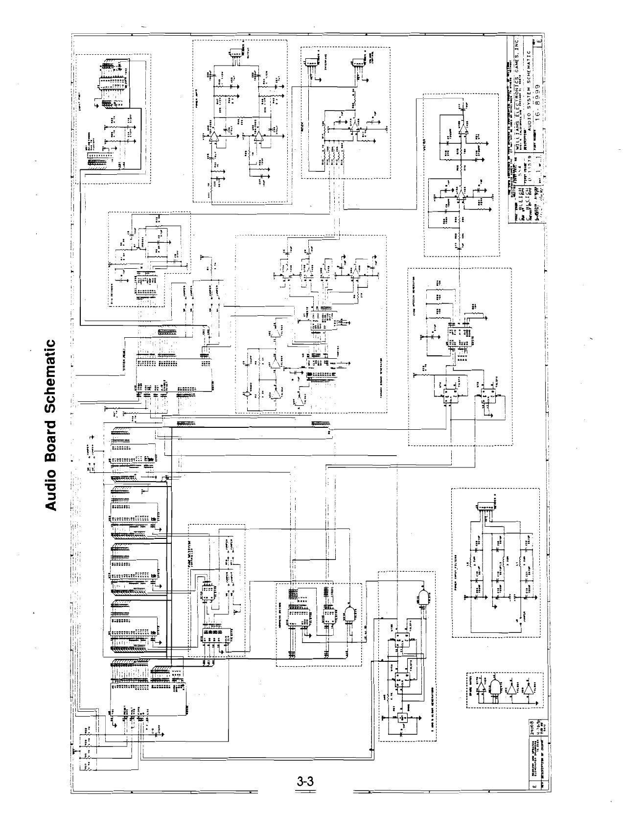
This page is a drawing, shown as the original scan.
cs evtene 2a {ie eveens re wy te onewayss pieog odo yonsAor Aem-6r
Ba
CPU Schematic Sheet 1 of 12
DL)
CPU Schematic Sheet 2 of 12
CPU Schematic Sheet 3 of 12
CPU Schematic Sheet 4 of 12
teesrenes te a il ttt A - LH
E
CPU Schematic Sheet 5 of 12
seszsas
CPU Schematic Sheet 6 of 12
CPU Schematic Sheet 7 of 12
CPU Schematic Sheet 8 of 12
bert btt rd sanesees_ 82] 35533335 ssaeszes_ 39! CPU Schematic Sheet 9 of 12 ery Gray fe years
85383335 ses8este
q Ft
3333 ETT) 338 3338 3838 Ssevoe gerd Sxeved 280¢F Qicoved ESG0F SScevnd GEER AEcavad Ste
Ti SassssEs Poti ti ty best bs ty prSttii ty h suggeaas! MoRBE dececeaneteZitiiee AE SeccazezaaeGageiia BEd eceazeeeet2Gaee
Ss33a553 serstRat Ge.
3-13
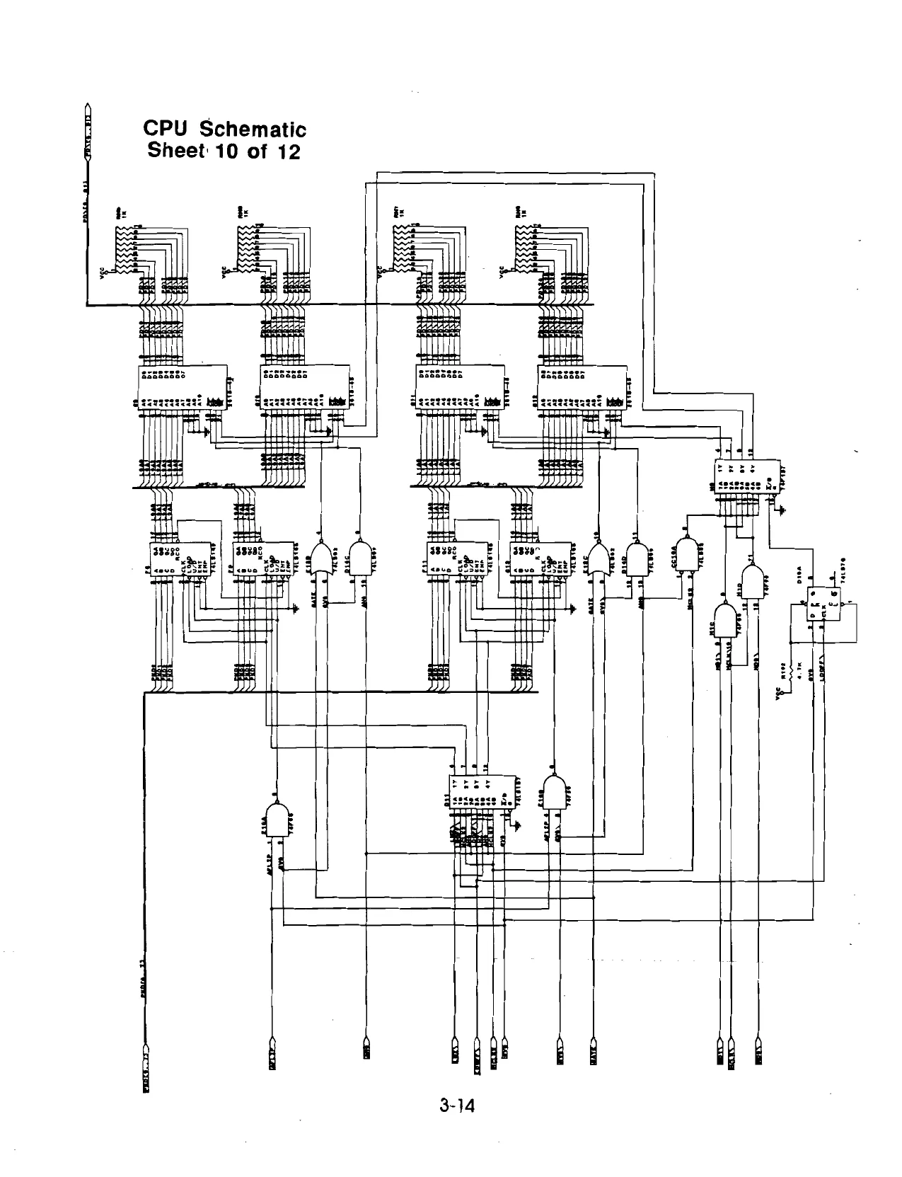
This page is a drawing, shown as the original scan.
CPU Schematic Sheet 11 of 12
3-15
CPU Schematic Sheet 12 of 12
3-16
auvog annos
? eo i i a ft
. & 7 auvog
dd NIXSDId uw ar + i ze - ae
{ Bg chap awe) sous wae
i dung Pa
jeaueg aamen OL
ONIMIM QYVOGHALNI NDISDIid
3-17
SEE
REFERENCE ‘A’
~” PIGSKIN Wiring Diagram
Vv |
|. WHT-RED. + SERVICE 4“, PLAYER 1 WHT-BLU- RIGHT COIN2 9“ Control ORG-BLK owe E urs] |see WHT-VIO TMI go Panel ORG-BRN Wwe REFERENCE 'A’ GRN TEST 56 Switches “ORG-RED we
ORG Ne
° ORG-YEL_PUNCH 3 ORG-GRN pa 7 5 ORG-BLU ATT. ADJ. Goin S YEL-GAN STAR
Counter BLK GND
ORG-VIO Control te
Panel YEL-RED
NC NC NC Switches YEL-ORG No
PUNCH
YOLOANNOD 3903 VAS Speaker YEL-ViO . YELGRY PASS ° VIO-BLK, ATT. ADJ. . YEL-BLU START. BLK __ GND SPARE ViO-BRN
JP6 REFEREN ENCE 'B’ SEE NOTE: THIS VIDEO CABLE IS REFERENCE 'C' PROVIDED FOR FUTURE USE
REFERENCE 'B'
REFERENCE 'A’ Video
Board Monitor
© a gS RED RED ne
Player One Joystick
KNOTNONR OD RED-BLU 7 a REFERENCE 'C' key __- Sound Board
raotrMHOoRnaDoT Zz oO a
3)
p= FI
AY
BLU SPEAKER +
No +—_—_—_———_——- | Speaker SPEAKER- _ VIO
vio SPEAKER g TNO TNOR® d > &
a + GRY-GAN 5 Power 5 GRY
"
2.
cc)
raat] Sienmwneo
TAMTNONR DD GND
rAaTMNOnoaeTN Player Two Joystick
Coin Switch and Meter Wiring
Option 1
+5V
Meter
JAMMA Pin 16
JAMMA Pin8
Option 2
ee aaa JAMMA Pin 16
SE al JAMMA Pin T JAMMA Pins
Wrong Way !
-[- JAMMA Pin T JAMMA Pin 16
Do NOT Connect the coin switches this way. This Circult is INCORRECT and will cause twice as many credits per coin.
CREDIT BUTTON
lw DIA. THRU 4 HOLES
3-21 ADJUSTMEN > DIA. THRU \ 16 “6-HOLES
ATTITUDE
6-915:
Control Panel Template
Diagram
»
Notes
PIGSKIN Inserted Jumpers
AUDIO BOARD P/N D-11581-4004
PIGSKIN CPU BOARD P/N C-13246-4004
WARNINGS & NOTICES
- For safety and reliability, substitute parts and modifications are not recommended.
- Substitute parts or modifications may void FCC type acceptance.
- This game is protected by Federal copyright, trademark and patent laws. Unauthorized modifications may be illegal under Federal law. This also applies to Midway logos, designs, publications and assemblies. Moreover, facsimiles of Midway equipment (or any feature thereof) may be illegal under federal law, regardless of whether or not such facsimiles are manufactured with Midway components.
her own expense, will be required to take whatever measures may be needed to
correct the interference.
MIDWAY MANUFACTURING COMPANY 3401 N. CALIFORNIA AVE. CHICAGO, ILLINOIS 60618