Two Tigers (Conversion Kit from Upright Tron) (0C67-00300-0000)
Two Tigers (dedicated) (Bally Midway, 1984) · Document · 11 pages · 9 sections · original scan
FIELD CONVERSION KIT |
TRON TO TWO TIGERS UR.
rally MIDWAY MFG.CO.
10601 W Belmont Avenue Franklin Park, tWinois 60131 USA
‘Phone (312)451-9200 Cable Address MIDCO Telex No.: 72-1596
0C67-00300-0000
ELECTRICAL BULLETIN: FOR ALL APPARATUS COVERED BY THE CANADIAN STANDARDS ASSOCIATION (CSA) STANDARD C22.2 NO. 1, WHICH EMPLOYS A SUPPLY CORD TERMINATED WITH A POLARIZED 2-PRONG ATTACHMENT PLUG
eee esac BLADES CAN BE FULLY INSERTED TO PREVENT BLADE
ATTENTION: POUR PREVENIR CHOCS ELECTRIQUES NE PAS UTILISER CETTE FICHE POLARISEE AVEC UN PROLONGATEUR. UNE PRISE DE COURANT OU _UNE AUTRE SORTIE DE COURANT, SAUF SI LES LAMES PEUVENT ETRE INSEREES A FOND SANS EN LAISSER AUCUNE PARTIE A DECOUVERT.
Cally MIDWAY . Vuutter You Fo Use our TOLL FREE nume_ers For SERVICE INFORMATION CONCERNING THIS GAME, OR ANY OTHER BALLY MIDWAY GAME YOU NOW HAVE ON LOCATION.
CALL US FOR PROMPT, COURTEOUS ANSWERS TO YOUR PROBLEMS
ANSWERS TO YOUR PROBLEMS. VIDEO =<» Continental U.S. 1-800-323-7182 PINBALL == Continental U.S. 1-800-323-3555 MIOWAY {0801 West Berman! Avenue Frontin Park tines, 60131 pene (18/48!-8200 u
- COPYRIGHT MCMLXXXV BY BALLY MIDWAY MFG. CO. ALL RIGHTS RESERVED NO PART OF THIS PUBLICATION MAY BE REPRODUCED BY ANY MECHANICAL, PHOTOGRAPHIC, OR ELECTRONIC PROCESS, OR IN THE FORM OF A PHONOGRAPHIC RECORDING, NOR MAY IT BE TRANSMITTED, OR OTHERWISE COPIED FOR PUBLIC OR PRIVATE USE, WITHOUT PERMISSION FROM THE PUBLISHER. THIS MANUAL IS FOR SERVICE USE ONLY, AND NOT FOR GENERAL DISTRIBUTION. FOR PERMISSION REQUESTS, WRITE: BALLY MIDWAY MFG. CO., 10601 W.
BELMONT AVE., FRANKLIN PARK, IL 60131
Printed in U.S.A.
The following Instructions wil! guflde you through converting your TRON game to a Two TIGERS game,
Refer to TRON PARTS AND OPERATING MANIIAL pages 5~2, 5~3, 5-4, and 5-5.
“NOTE: Some parts are used again, save all parts and hardware.
- Turn game off, unplug It from its! power source, and open al! Its' access doors,
- Remove Item 3, HEADER RETAINER=IIPPER, Remove HEADER and PLASTIC ENGE PROTECTOR. Save tor use with new header.
- Disconnect contro! panel cable connectors and ground strap. Release contro! panel locking clamps - remove control pane}.
- Working on underside of control pane! = disconnect pin connector from P.C. hoard at Optical Encoder Dise Assembly. Loosen set screws with 5/64 allen wrench to remove knob and shatt.
Remove (4) hex nuts with 3/8 nut driver, Relocate OPTICAL ENCODER DISC ASSEMALY on new control panel. Relnstatl Knob and Shaft ~ tighten (2) set screws to lock shaft, Connect pin connector to P.C. board.
New control panel! Is complete. Set aside unti{ Step 20.
5, Remove fasteners and WINDSHIELD RETAINING RRACKET, item 8, Remove items 9 and 10, CONTROL SHELF LIGHT ASSEMBLY and LAMP PROTECTOR.
- Remove (4) fasteners securing top of WINDSHIELD, Item 7 in place. It may be necessary to pry left and right side of Windshield white pulling it out through front of cabinet.
- Carefully Vift out VIEWING GLASS, Item 17, Note wood cleats glass rests on - these cleats are removed as described in Step 12.
- Remove RFZEL and PLEX! GLASS ASSEMRLY. Rezel and screws will be reattached after monitor relocation, NOTE: Smoked Plex! is not used on TWO TIGFRS kit.
- At upper rear of cabinet remove SCENERY LIGHT ASSEMBLY, Item 6, Re sure to disconnect connector.
- Remove ILLUMINATED REAR SCENE and SCENERY BRACKET, Item 7.
- Locate and disconnect the two pin monitor power connector and video cable at chassts' P.C. board. Orientation of video cable connector can be reinstalled only one way. Remove ground wire and cl! from chassis. Loosen and remove (4) 1/4-20 Hex. bolts at side brackets. Make sure all cables are cleared from the path of the monitor "U" channels. Grab securely and pull monitor out along stde brackets until clear of cabinet. Place monitor in a safe place. Loosen and remove (4) Hex. head bolts from "U" channels on monitor,
-1~
13.
15.
16.
17.
18.
19,
20.
21.
22.
23,
24, Remove Side Brackets from plastic locating pIns. Save screws for mounting new monitor brackets. Using a hammer and chisel, loosen and remove TRON Glass Support Rails at stdes of cabinet. See iliustration.
Spray any exposed wood areas with flat black paint after rail removal, Position MONITOR LOCATING TEMPLATE over locating pins and mark new locations onto cabinet sides as Indicated on temptate.
At these (4) new locations drill 3/8 diameter holes 1/2" deep. Caution - do not drill through cabinet sides.
Install plastic locating pins at these new locations.
Attach new monitor mounting brackets over jiocating pins & secure with (8) Hex Hd. wood screws. Flange must face front of cabinet.
Install monitor horizontatly through front of cabinet aligning slots on monitor tlanges to holes on new mounting brackets.
Use self-tapping hex head screws with wahser and 5/16 nut driver to fasten monitor to brackets. Tighten securely. Reattach bezel! to brackets without smoked plexi glass.
See Illustration,
See illustration.
Clean and instal! Viewing Glass and Header.
Guide cables from new contro! panel Into cabinet and connect accordingly. Attach ground strap to control panel. tong cable attaches to pin connector J6 on Super Sound 1/0 board AQ82-90913-E000. Secure this cable to master cable using tie wraps, Lock panel In place with clamps.
Disconnect and remove the logic board set for EPROM change. Refer to EPROM chart. Set dip switches as Indicated,
Reassemble logic board set, {nstali and reconnect al! connectors and secure with Block and Rracket Assembly.
Replace all access doors.
Side decal application ~ see Instructions provided.
STEP 12.
REMOVE 2 TRON GLASS SUPPORT
RAILS AT SIDES OF CABINET.
STEP 17.
UPPER GLASS RETAINING BRACKET
FASTEN WITH (4) 10-32 x 3/4 PAN HD
MACHINE SCREWS AND EXTERNAL STAR
WASHER. LOCATE AT EXISTING T-NUTS.
SECURE FRONT END OF RETAINER
WITH (4) HEX HD. WOOD SCREWS.
STEP 18.
LOWER GLASS RETAINING BRACKET
FASTEN WITH REMAINING (4)
10-32% 3/4 PAN HD. MACHINE SCREWS
AND STAR WASHERS. LOCATE ON
EXISTING GLASS RAIL. FASTEN ALL
SCREWS ANO FASTENERS SECURELY.
NBENNFNH Awe Ltist OF MA NCLUDED tN YOUR Two TIGERS To
PART_NO.
0€67-00300-0000
SEE EPROM CHART AA11~00014-0000 AC67-00004-0000
AC67-00016-00XF 0C67-00106-0000 0C67~00900-O00XF 0C67-00901-00xF 0537-00903-0022 0C67-00904-0000 0555-0090 1-0000 0636-00101-0000 0017-00101-0141 0017-00101-0144 0017-00101-0660 0C67-00903-0000 OR PARTS CONVERSION KIT TRON CONVERSION
DESCRIPTION
FIELD CONVERSION KIT TRON TO TWO TIGERS MANUAL FPROMS VIDEO SIGNAL CARLE ASSY, CONTROL SHELF ASSY. COMPLETE W/CABLE ASSY. GLASS RETAINING ASSY. GLASS PRKT. LONER HEADER VIEWING GLASS GLASS CHANNEL 20" MONITOR LOCATING TEMPLATE LOCATING PINS; PLASTIC RAIL=MONITOR MOUNTING 8 X 11 UNS HXW 1 GIM ST ZN 10-24 X 10 SLT HXW DC ST ZN 10-32 X 12 SLT BOR U MS ST ZN SIDE DECALS
DECAL_INSTALLATION INSTRUCTIONS
READ THE FOLLOWING INSTRUCTIONS THROUGH COMPLETELY AT LEAST ONCE BEFORE ATTEMPTING TO
INSTALL THE DECAL(S) THEY CONCERN! !
THE DECAL(S) ARE COMPOSED OF THREE (3) PARTS: 1)A HEAVY WAXED RACKING SHEET WHICH COVERS THE STICKY SIDE OF THE DECAL, 2) THE DECAL ITSFLF, AND 3)A THIN MASKING SHEET WHICH 1S ON THE FRONT SIDE OF THE MECAL TO PROTECT IT AND TO AID IN ITS INSTALLATION.
4 8 eH HHH HH FH TO INSTALL THE DECAL(S), PROCEED AS FOLLOWS: FF HERA RRR ES
1 BE SURE THE AREA WHERE YOU ARE GOING TO APPLY THE DECAL IS CLEAN AND FREE OF ALL DIRT, GREASE, AND GRIME.
- USING ANY SPRAY-ON GLASS CLEANER, THOROUGHLY WET DOWN THE AREA WHERE YOU INTEND TO PLT THE DECAL.
- REMOVE THE HEAVY WAXED BACKING SHEET FROM THE DECAL RY POSITIONING IT FACE UP ON A FLAT SURFACE; GOING TO ANY CORNER; AND RENDING THIS CORNER UP SLIGHTLY TO SEPARATE THE DECAL AND THIN MASKING SHEET FROM THE HEAVY WAXED BACKING SHEET.
4, SLOWLY AND CAREFULLY PEEL THE HEAVY WAXED BACKING SHEET AWAY FROM THE DECAL AND MASKING SHEET.
- PLACE THE DECAL ON THE GAME CARINET OVER THE WET GLASS CLEANER YOU JUST APPLIED. (THIS WILL ALLOW A SMALL AMOUNT OF FINAL POSITIONING TO BE DONE AFTER THE DECAL 1S APPLIED TO THE GAME CABINET.)
- SMOOTH THE DECAL.
- ALLOW THE DECAL TO RECOME FIRMLY AFFIXED TO THE GAME BEFORE PROCEEDING TO THE NEXT STEP.
- REMOVE THE THIN MASKING SHEET FROM THE DECAL AT THIS TIME RY MOISTENING IT WITH A WET CLOTH OR SPONGE. RUA WITH FINGER TIPS (NOT NAILS) FROM A CORNER EDGE TOWARD ITS CEN- TER. PEEL THE THIN MASKING SHEET BACK OVER ITSELF TO REMOVE IT. DO NOT PULL IT STRAIGHT AWAY FROM THE CABINET.
TRON TO TWO_TIGERS CONVERSION
OPTION SWITCH SETTINGS
SITIITITITTITTL/ 1 SWATCH NOs 1 - AT B 3 - LOCATED ON SOUND 1/0 P.C. BOARD DHTHTHTIITT
SW#1 SW#2 Sw#3 Sw#4 SW#5 SW#6 SWH7 SW#8 SWHO SW#10 DURING GAME PLAY:
USED USED USED. USED USEN USED
SINGLE FIRE MUST RAPID FIRE REMAIN OFF
®* NO CREDIT DOG FIGHT 1 CREDIT DOG FIGHT
#* ONE COIN METER TWO COIN METERS
#* NORMAL OPERATION FREEZE VIDEO
SILIITITISIILLI 1 SWVTCH NO. 3 - AT D 14 - LOCATED ON SOUND 1/0 PC. BOARD ////////////1///
SwHt *Sw#2 *Sw#3 *Swe4 # NORMAL OPERATION OFF SOUND 1/0 DIAGNOSTIC MODE ON
#% NORMAL OPERAT!ON RAM/ROM TEST INDICATES TEST RESULTS VIA YELLOW L FD ON SOUND 1/0 ROARD: FAST FLASH = RAD ROM SLOW FLASH = RAD ROM OFF
#3 NORMAL OPERATION OFF OSCILLATOR TEST ON
NORMAL OPERATION OFF FILTER TEST ON
*® NO EFFECT {F SW#1 OF SWITCH NO. 3 IS IN THE "OFF" POSITION #* FACTORY RECOMMENDED SETTINGS PART NO. M051-00C67-A007
EPROM_CHART REFERENCED FOR STEP 21
POSITION
Al CRI C1. el
MCR/ Il VIDEO GEN. A082-91399-G000
POSITION
CPU BD.
A082- 90010-C000
POSITION
AT AB AQ EPROM
FG.-3 a) mony Cr)
EPROM
PROG.-0 oy "22 "23 RG. -0 " =-1
SND.-0 moony PART NO.
CATA=22AXC-MXFI) C67A=22AXC-LXFD C67A-22AXC=JSXFD. CATA=22AXC= JXFD
PART_NO.
C67A=22AXC=-CXFD C67A=22AXC=NXFD CATA=22AXCHEXFED CA7A=22AXC=FXFD C67A=22AXC-AXFN C67A-22AXC-RXED
PART NO.
C67A~22AXC=AXCD, C67A-22AXC=RXCN C67A-22AXC-CXCN
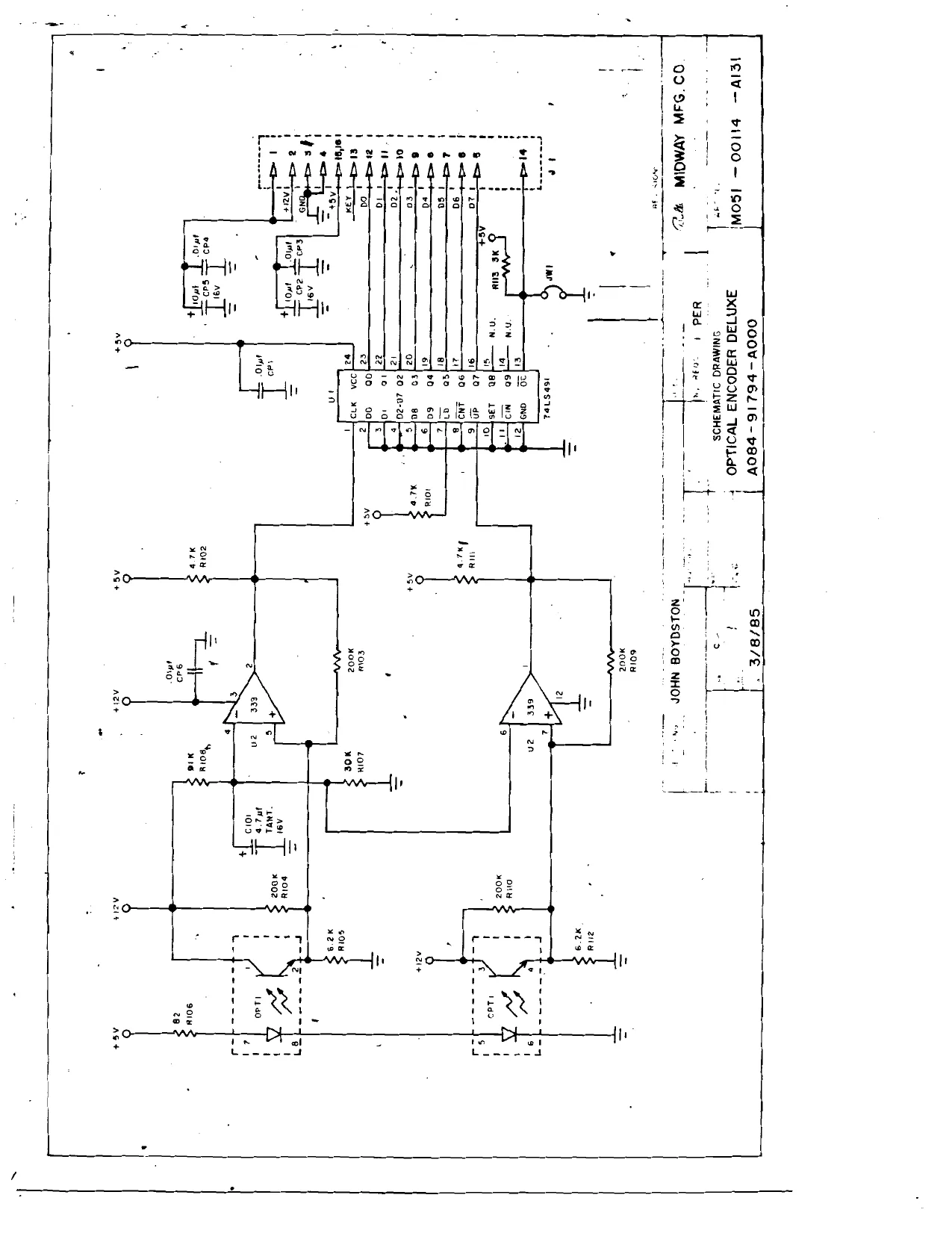
This page is a drawing, shown as the original scan.
CONCENTAICITY TYR = 002 a i FRANKLIN PARK IL 80191
FRACTIONAL 2 64 + REVISIONS
ceca os | OPTICAL ENCODER DELUXE — [marwo ~ ANGLE 212" PRES 0-51 -0-0-1-1-4 -A:1-3-0 DO NOT SCALE DWG. : A080-91794 ~A008 SHEE / OF L