Warlords DP-175-1st-01B
Warlords (Atari, 1980) · Drawing Package · 1 pages · original scan
Sync Generator Circuitry Address Decoder
i
ome Hoe a 4 [as
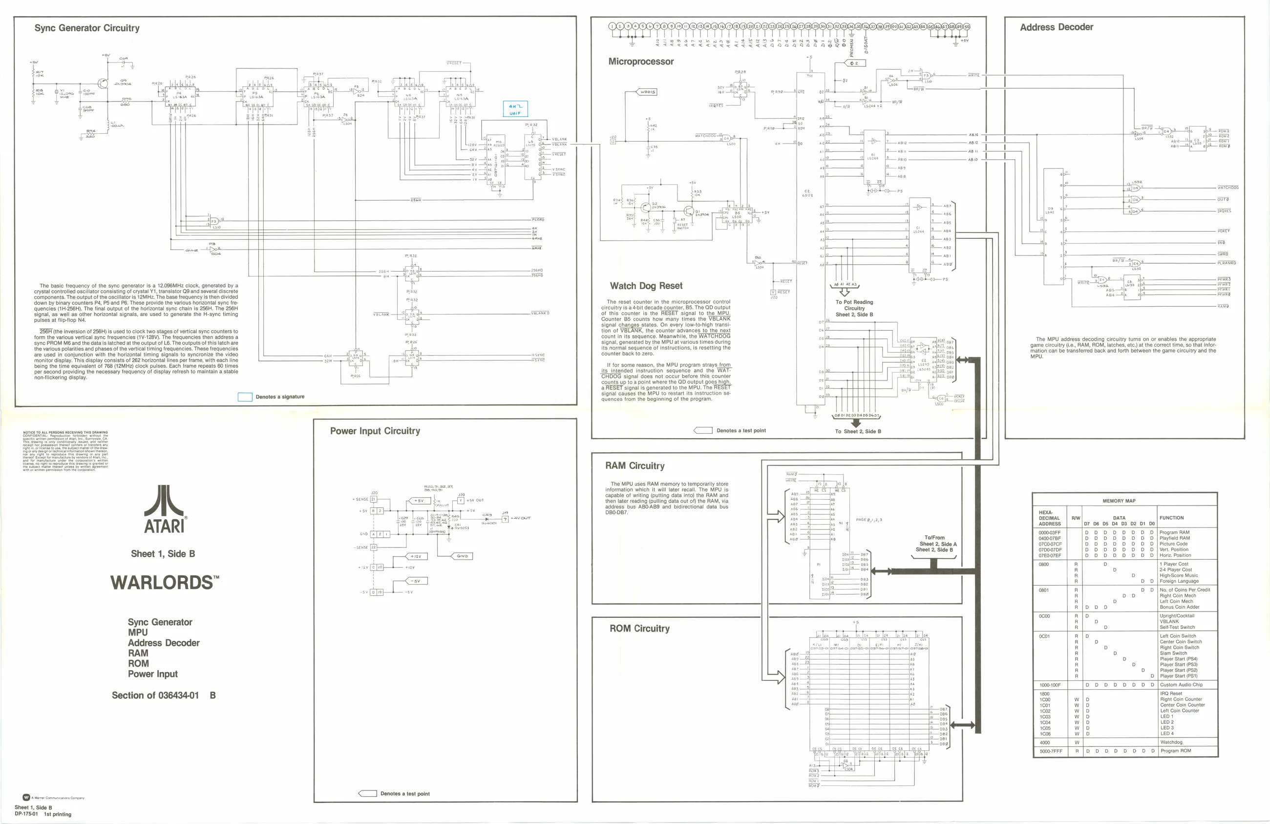
‘Tho basic frequency of the sync generator is a 12086MHz clock, gonerated by a sos 9, crystal controlled oscilator consisting of crystal V1, transistor Q9 and several discrete Watch Dog Reset “a Components. The output of th oscillator is 12MH2. The base frequency is then divided ‘down by Binary counters Ps, PS and PB, These provide the various horizontal syne fe- ‘The reset counter in the microprocessor contro! ‘To Pot Reading icles (1H-256H), The final output of the horizontal sync chain is 256H. The 256 circuitry isa bit decade counter, 85. The QD output Circuitry Signal, as well as other horizontal signals, are used to generate the H-syne timing aR fof this counter is the RESET signal to the MPU ‘Sheet 2 Side B pulses at fiptlop Na. '85 counts. how many times the VBLARK signal changes states. On every low-to-high tran BF the inversion of256H) is used to clock two stages of vertical sync counters to tion of VBLANK, the ountor agvane {orm the various vertical syne frequencies (1V-128V). The Trequencies then adress a count in its sequence. Meanwhile, the ‘sync PROM M6 and the data is latched at the output of L6. The outputs of this latch are ‘signal, generated by the MPU at various times during eee c aoe eee FSM HOR chine en THE EaTTeGL IS ao ta ‘the various polarities and phases of the vertical timing frequencies. These frequencies its normal sequence of instructions, is resetting the pare eae * pce prs ope a cgescnbpir “ye are used in conjunction with the horizontal timing signals to syncronize the video ean SYNE counter back to zero. — fp hts ‘can be transferred back and forth between the game circuitry and the monitor display, This display consists of 262 horizontal lines per amo, with each line Sou ae I being the time equivalent of 768 (12MH2) clock pulses. Each trame repeats 60 times If for some reason, the MPU program strays from per second providing the necessary frequency of display refresh to maintain a stable its_intended instruction sequence and the WAT- | honiekering dlepay. “CHDOG signal does not occur before this counter ‘counts up toa point where the QD output goes high, oF | RESET signal ie generated tothe MPU. Tho RESET an Signal causes the MPU to restart its instruction se ram ‘quences trom the beginning of the program. ° a
peso at resons pce rs ors Power Input Circuitry <<] Denotes a test point To Sheet 2, Side B
RAM Circuitry
‘The MPU uses RAM memory to temporarily store Information which it will later recall. The MPU is capable of writing (putting data into) the RAM and then later reading (pulling data out of the RAM, via ‘address bus AB0-AB9 and bidirectional data bus Dso087, MEMORY MAP. A.
ATARI
Sheet 1, Side B
WARLORDS"
HEA.
DECIMAL FUNCTION
ADDRESS 00003 Program RAM owoa7er Prayfiod RAM o700970F Picture Code o700070F Ver. Position O7E007eF Horiz Position 1 Prayer Gost 124 Player Cost HighScore Music Foreign Language ‘No.of Coine Per Credit Fight Coin Mech Lett Coin Mech Bonus Coin Addor
UprightOoekta BLANK SoltTest Switen
Lott Coin Switch Genter Goin Switch Fight Goin Switen ‘lam Switen Player Start (PS4) Payor Start (P53) Player Start (P52) Player Start (P51) [Custom Avo Chip TRO Rost Fight Coin Counter (Canter Coin Counter Lett Coin Counter Leo Leo 2 Le3 les
‘Watendog Program ROM ‘Sync Generator MPU Address Decoder RAM ROM Power Input ROM Circuitry
xe ie
Section of 03643401 B zls|sseseee
<1 Denotes atest point ‘Sheet 1, Side B DP-75.01 1st printing