Bionic Commando
Bionic Commando (Euro) (Capcom, 1987) · Manual · 56 pages · 50 sections · original scan
Wn abl,
\ a ¢ g q Ig §
NOILONYLSNI
CAPCOM, USA INC.
Invites You To Use
OUR TOLL FREE NUMBER FOR SERVICE INFORMATION CONCERNING THIS GAME, OR ANY OTHER CAPCOM GAME YOU NOW HAVE ON LOCATION.
CALL US FOR PROMPT, COURTEOUS
ANSWERS TO YOUR PROBLEMS.
Continental U.S. (800) 843-4632 California Only (408) 745-7081
PAGE
O©OMNONTA WON =
PPR WWD OODNOGA a TABLE OF CONTENTS
Game Play Dip Switch Settings Location & Set Up Coin Door Maintenance Control Panel Buttons Coin Control Joystick Assembly WICO Joystick Assembly Main AC Wiring Diagram Service Information On Monitor Schematics (Board A) Schematics Piggy Back Schematics (Board B) Board Interconnect Jamma Connector Warranty
This page carries no recoverable text. It is a drawing or a photograph. See the original scan.
Story: It has been 10 years since the devastating world war. The enemy surprised us with gigantic missiles this time. After the enemy attack, our army succeeded in sending the special commando unit to infiltrate the enemy army. Their deadly mission was to discover the enemy's plans and to destroy the missiles. What can the special commando unit expect? *There are 5 stages all together. If the player fails to prevent the missile from launching at the Sth stage, he should go back to the 4th stage. If the player succeeds, the clear message will be shown.
Stage 1 Wasted forest, Inside of enemy's area. Stage 2 Outside of enemy's base. The player should climb enemy's fortress built on a mountain. Stage 3 Inside of enemy’s base. As soon as the player enters, he falls and reaches a water main. Then he proceeds to a factory, a freezer, and the headquarters.
Stage 4 The player proceeds from the headquarters to the control tower. He goes to the central control tower by elevator. Stage 5 It starts at a site of the testing grounds. The player proceeds to the missile and climbs over it. He should keep going up through the headquarters, then fights with cadets in front of a bronze statue.
DIP SW - BIONIC COMMANDO
DIP swA
| ITEM | DESCRIPTION | 1 | 2 | 3 | 4 | 5 | 6 | 7 | 8 |
NUMBER | 3 PLAYERS OFF | OFF
| OF | 4 PLAYERS | ON | OFF |
PLAYERS | 5 PLAYERS OFF] ON 7 PLAYERS ON | ON TABLE ON UPRIGHT OFF 20,000, 40,000 & every 60,000 OFF | OFF
| BONUS | 30,000, 50,000 & every 70,000 | ON | OFF |
| POINTS | 20,000, and 60,000 only | OFF | ON |
30,000, and 60,000 only ON | ON NORMAL OFF | OFF DIFFICULTY | EASY ON | OFF (LEVEL) | DIFFICULT OFF | ON VERY DIFFICULT ON | ON NOT USED NOT USED
DIP swB
ITEM DESCRIPTION 1 2 3
| 1 | COIN | / | CREDIT | 1 [OFF | OFF | OFF | |
| 1 | / | 2 | ON | OFF | OFF | |||
| 1 | / | 3 |OFF | ON | OFF | |||
| cont | 4 | / | 4 | ON | ON | OFF | |||
| 1 | / | 6 |OFF | OFF | ON | |||
| 1 | / | 1 | ON | OFF | ON | |||
| 1 | / | 1 |OFF | ON | ON | |||
| 1 | / | 1 | On | ON | ON | |||
| 1 | COIN | / | CREDIT | 1 | OFF | OFF | OFF |
| 1 | / | 2 | ON | OFF | OFF | ||
| 1 | / | 3 | OFF | ON | OFF | ||
| coiIn2 | 14 | / | 4 | ON | ON | OFF | ||
| 1 | / | 6 | OFF | OFF | ON | ||
| 1 | / | 1 | ON | OFF | ON | ||
| 1 | / | 1 | OFF | ON | ON | ||
| 1 | / | 1 | ON | ON | ON | ||
| TEST | NORMAL | OFF | |||
| MODE | TEST | ON |
SCREEN | NORMAL OFF FLIP ON
goovraodFr er ono0PN
Oo LOCATION AND SETUP
INSPECTION Remove the game from its shipping crate.
Inspect the entire outside of it for any signs of damage.
Any scratches?, dents?, cracks?
Any broken controls?
Just look it over closely and make a note of any signs of damage.
Remove the shipping cleats from the bottom of the cabinet.
Install the four levelers, one at each corner of the cabinet.
Level the cabinet
Open the cabinet and inspect the inside of the game for any signs of damage.
Also check to make sure all plug-in connectors on the wire harness are firmly seated.
Replug any connectors found unplugged. DO NOT FORCE PLUGS ONTO CONNECTORS. DO NOT FORCE PLUGS TOGETHER. If it won't go on easily, assuming the keys are lined up, it either does not belong there or is damaged
Make sure all printed circuit boards (P.C.B.'s) are firmly seated in their connectors. These connectors are also keyed. The P.C.B.'s will only go into them one way without being damaged
Check all major subassemblies to be sure they are mounted securely.
Power supply. Control panel(s). T.V. monitor. Other P.C.B.'s and/or P.C.B. rack, etc Power Chassis.
Make a note of any problems that can't be easily corrected. Call your distributor and/or service man about your problem list.
COIN DOOR MAINTENANCE
The magnet that is fitted to the mechanism, should be kept clean from foreign particles. The magnet can be cleaned by swinging the gate open. (as shown in Fig. 1). Remove metal filings from the magnet by guiding the point of a screwdriver along the edges of the magnet, such that the filings cling to the screwdriver.
The mechanism can be cleaned by immersing in water using a small brush to clean the mechanism. Rinse the mechanism with boiling water and dry with compressed air.
If the above procedures are not successful, check for worn, bent or damaged parts and replace where necessary. Removal of Mechanism
To remove the coin selector: Unscrew the two screws (as shown in Fig. 2)—swing rear of selector body away from the lock-out side and withdraw.
The Gold Mech Acceptors are designed to require a minimum of maintenance and field adjustment. Coins are checked by diameter and thickness, weight, metal content, bounce, and for ferromagnetic coins such as nickel and steel, a rim test is also used.
Coin switch
The coin switch comes in two different spring tensions—identified by the color of the plastic boss at the wire’s pivot point.
Red: Light tension—U.S. 25¢
White: Heavy tension—heavy foreign coins
*WICO BUTTON
Ws
Push Button Holder with Molded Switch and Embossed Tabs
Wico P/N 15-9123-01
*COIN CONTROL BUTTON Locknut
Wico P/N 19-0254-01
ITEM NO.| DESCRIPTION
Button Plunger Button Spring Button Bezel Switch Acluator Washer Spring Contact Washer Washer Spring Contact Plate Fixing Nut COTA
- WHERE APPLICABLE
COIN CONTROL JOYSTICK *
- Where Applicable ITEM NO, DESCRIPTION
1 1.25" Knob & Shaft 2 2” Washer 3 Pivoi Cone 4 S.T. Nylon Hub 5 Return Spring 6 Spring Bushing 7 Switch Mount Bracket 8 Screw #10 x 4," 9 Switch Protector 10 Micro Switch W Screw #4 x 3," 12 Side Mount Switch 13 4/8 Way Actuator 14 E-Ring
WICO JOYSTICK *
15-9468 Ball Handle
15-9471 2” Washer
15-9473 Spring
30-0933 va" E Ring
15-9478 Switch Actuator ( 500" Dia. for 4-Way Joystick)
15-9470
Switch Actuator ( 600" Dia tor 2- & 8-Way Joystick)
Wico Joystick Assembly (700-0163-01)
- Where Applicable
3 A Fuse
TO
MARQUEE
LIGHT
NOISE
FILTER
ISOLATION TRANSFORMER
(MANDATORY) 117 VAC (if Wells Gardner monitor) TV OR POWER
100 VAC (if Nanao or Sanwa monitor)
117 VAC
POWER SUPPLY CIRCUIT I\ p—+ | coin DOOR © | LAMPS
SWITCHING POWER PCB SUPPLY POWER
SERVICE MANUAL
wells-Gardner elecTRONIcs 2701 N. KILDARE, CHICAGO, IL 60639 CORPORATION 312/252-8220 TELEX: 25-3286 FAX: 312-252-8072 SERVING CONSUMER AND INDUSTRIAL ELECTRONICS FOR MORE THAN 60 YEARS.
THE PRISMATIC™
WELLS: BY “GARDNER
COLOR SPECIFICATIONS
CRT
@ From 9” to 25” diagonal measure © P22 phosphor
- Polished faceplate standard: variety of optional faceplates and transmittances available. © Stripe trio spacings (standard): 0.62 mm (9”), 0.66 mm (13), 0.82 mm (19°), 0.82 mm (25”). © Optional finer pitches available.
INPUT SIGNALS
Video: RGB analog, 1v to 5v peak-to-peak (adjustable with contrast control), 4.7k ohm input impedance, 40 usec to 50 usec active video. Optional inputs available: Negative video RGB analog 0-0.75v, 75 ohm input impedance Composite video (NTSC} Both composite video and RGB analog: Both signal sources can be connected to the monitor at the same time. Monitor display can be switched from one to the other, at anytime at pixel or vertical frame rate. Sync: TTL positive or negative going, separate or composite. Input impedance: 20K ohms for positive going sync; 12K ohms for negative going sync.
HORIZONTAL SCAN
® Width: Adjustable with just one coil to accommodate active video from 40 usec to 50 usec © Frequency: 15.1 kHz to 16.8 kHz standard, higher scan frequencies avaliable. © Linearity: * 5%
PICTURE SIZE REGULATION em,
VERTICAL SCAN
© Frequency: 47 Hz to 63 Hz © Linearity: + 5%
GEOMETRIC DISTORTION
@ t 2% (max) VIDEO CHARACTERISTICS © Bandwidth (-3 db): 12 MHz typical © Rise Time: Less than 50 nanoseconds © Overshoot (max): 5%
MECHANICAL
@ The 19" monitor is also available in universal mount brackets. The monitor can be mounted in the user's cabinet horizontally or vertically. Contact your sales representative for details
© The standard Prismatic-25™ 25’ monitor is available as a kit - without a frame. Custom frames can be furnished.
@ The standard Prismatic-9™ 9° monitor is available as akit without a frame: Also available in chassis form adaptable to individual customer requirements. Contact your sales representative for details.
USER ADJUSTABLE CONTROLS AND ADJUSTMENTS
Brightness, Contrast, Horizontal Hold, Horizontal Size, Horizontal Raster Position, Horizontal Video Position, Vertical Hold, Vertical Size, Vertical Raster Position, Focus. Custom Control Location available.
POWER INPUT © 120 VAC +10% -15%, 50-60 Hz, 85W (max) Isolation transformer required: furnished with monitor as an option
ENVIRONMENTAL CONDITIONS © Operating temperature 0° to 55°C. Complies with ULL. C.S.A., and D.H.H.S, radiation performance standard (composite video).
RESOLUTIONS © Standard CRT © Fine Pitch CRT 9” 280 Pixels x 240 Lines 410 Pixels x 240 Lines 13” 400 Pixels x 240 Lines 640 Pixels x 240 Lines 19"" 400 Pixels x 240 Lines 640 Pixels x 240 Lines 25” 560 Pixels x 240 Lines N.A
Copyright © 1987. Wells-Gardner Electronics Corporation All rights reserved.
- SPECIFICATIONS ARE SUBJECT TO CHANGE IN ORDER TO ASSURE YOU THE LATEST IN DISPLAY TECHNOLOGY.****
THIS MANUAL APPLIES TO THOSE MONITORS WITH SERIAL NUMBERS OF 576001 AND ABOVE.
WARNINGS
- Power Up Warning- An isolation transformer must be used between the AC supply and the AC plug of the monitor before servicing, testing or operating the monitor since the chassis and the heat sink are directly connected to one side of the AC line which could present a shock hazard. Before servicing is performed, read all the precautions labelled on the CRT and chassis.
2.| X-RAY RADIATION WARNING NOTICE
- High Voltage- This monitor contains HIGH VOLTAGES derived from power supplies capable of delivering LETHAL quantities of energy Do not attempt to service until all precautions necessary for working on HIGH VOLTAGE equipment have been observed
- CRT Handling- Care must be taken not to bump or scratch the picture tube as this may cause the picture tube to implode resulting in personal injury. Shatter proof goggles must be worn when handling the CRT. High voltage must be completely discharged before handling. Do not handle the CRT by the neck
5.|_ PRODUCT SAFETY NOTICE
AC CONNECTORS AND TERMINALS ALL MONITORS EXCEPT THOSE WITH MODEL NUMBERS ENDING WITH 2 OR 6: WELLS-GARDNER END WG. Part No. Molex Part No.
| Plug | 6A0396-001 | 19-09-2029 |
| Pins Male | 30X0759-001 | 02-09-2101 |
USERS’ END Receptacle 19-09-1029 Pins, Female 02-09-1101" or 02-09-1116" MODEL NUMBERS ENDING WITH 2:
WELLS-GARDNER END WG. Part No Molex Part No
| Plug | 6A0376-002 | 03-09-2022 |
| Pins, Male | 30X0759-001 | 02-09-2101 |
USERS’ END Receptacle 03-09-1022 Pins, Female 02-09-1101"
or 02-09-1116" MODELS NUMBERS ENDING WITH 6: WELLS-GARDNER END WG Part No AMP Part No
| Receptacle | 6A0402-001 | 350778-1 |
| Pins, Male | 30X0761-001 | 350538-1 |
USERS’ END Plug 350777-1 Pins, Female 350537-1 ** or 350851-1 **
*-1101 is used for 20-14 AWG wire and insulation diameter range 0.065"-0.160" -1116 is used for 22-18 AWG wire and insulation diameter range 0.060"-0.120" ** 350537-1 is used for 20-14 AWG wire and insulation diameter range 0.130”-0.200" 350851-1 is used for 24-18 AWG wire and insulation diameter range 0.040”-0.100"
10.
11, USER ADJUSTMENTS
. BRIGHTNESS CONTROL VR6 This control has been preset at the factory. However, when the video signal is applied to the monitor, a slight adjustment may be desired, Adjust this control such that the illumination is just barely extinguished from portions of the display which should be black . CONTRAST CONTROL VR7 Adjust the contrast control for the desired picture intensity.
- FOCUS CONTROL Adjust the focus control, located on the high voltage unit (71), for maximum over-all definition and fine picture detail . HORIZONTAL HOLD CONTROL VR2 With the monitor being driven with the display signal, connect one jumper between TP1 and TP2 and another jumper between TP3 and TP4. Adjust the horizontal hold control until the picture stops sliding horizontally. Remove the jumpers. Do not use the horizontal hold control for horizontal centering, (See #5)
TP3 HV 7~\ suut- “ “Down
ar, “og Screen” mS ak, ase cilia womiz vigeo ee < +H syne HORIZ HOLD / +V SYNC VERT RASTER POS ~ eno VERT SIZE VERT HOLD ~/ BRIGHTNESS ~~ CONTRAST
FIG. 1A
BLUE BLUE DRIVE CUT OFF GRN oan | GREEN \d HORIZ cut oFF | SIZE RED ORIVE-> HORIZ RASTER POSITION FUSE
rocus% /
HORIZ HOLO ~ \ +v.svt
BRIGHTNESS: é CONTRAST
FIG. 1B
TROUBLESHOOTING CHART
NO PICTURE SEE NOTE 4
YES
v YES CRT FILAMENT LIT NO.
CHECK FOR GATE f cHeck | PULSE AT ICI FILAMENT PINT2 ciRcUIT
CHECK ALONG VIDEO No. | CHANNEL FROM VIDEO | INPUT AT Pi TO VIDEO OUTPUT TRANSISTORS ON NECK BOARD Y a Y CHECK FOR GATE PULSE OUTPUT FROM IC2, PIN 12
CIRCUIT
REFER TO SYN PROBLEMS CHART
SEE NOTE 8 SYNC PROBLEMS
NO HOR SYNC | No Verr S¥Ne REFER TO NO. HIGH VOLTAGE HART
CHECK FOR OPEN HORIZONTAL YOKE
J CHECK FOR SHORTED B- REGULATOR IC4 PINS 1-4 NO HIGH VOLTAGE
CHECK B- (123V)
| B- GREATER | NO | CHECK AC. |
z ATIC4. PINA NECK }SO yp! |
| HAN130 VDC] | goaRD.P202 PIN3 | [8 | INPUT |
Ica
USING VARIAC. DECREASE AC INPUT TO ZERO THEN SLOWLY INCREASE AC SUCH THAT B.
MONITOR OPERATES. IC4 OK LOOK FOR CAUSE OF ge| SHORTED IC4 OVERLOAD SHORTED | CONDITION SHORTED Q11 FOR EXAMPLE
123 VDC CHECK FUSE IF FUSE IS OPEN. CHECK FOR SHORTED HOR OUT PUT TRANSISTOR Qli AND. | SHORTED B~ REGULATOR. IC4
MONITOR STILL DOES NOT OPERATE
CHECK WHETHER HOR OS. LATOR IS OPERATING CHECK WAVEFORM » AND IC 2. PINS 1.2.3.4 AND 16
Y CHECK RETRACE, [BR TUNING CAPACI TOR C36 ali sd
HV HOLD DOWN CIRCUIT IS PREVENTING MONI TOR OPERATION AT NORMAL AC INPUT. CHECK FOR FAULTY CONDITION CAUSING HV TO BE TOO HIGH EXAMPLE C36 DECREASED IN VALUE
CHECK HV HOLD DOWN
NO VERT SYNC HOR SYNC OK
CHECK SYNC —___¥ NO HOR SYNC VERT SYNC OK CIRCUIT O10. 012. 1C2
SEE NOTE 8
Y VERTICAL SWEEP PROBLEMS
AMPL CKT |
| aM | BRIGHT. THIN | wo. on very | | [oueck |_[ ouecx |
| WAVY LINE AT | UITTLE VERTI FB} 2av | ware) | |
| Y | Y | CENTER OF CRT | cau sweep | | SUPPLY |
ec | CHECK HOR SYNC - J INVERTER CKT Q6 Y
CHECK FOR OPEN VERT! Cheek CHECK Geer Cat YOKE WINDINGS OR ea 2 es VERTICAL YOKE PATH L
| [ cHeck vermicat osc | _ | Y | eR OCKNG) | | CHECK VERTICAL |
| | (ATOR AND TRIGGER CKTS | CHECK HOR | CHECK VERTICAL | | OC eTOR | DRIVE AND FEED | |
| [ic2sbins 012 AND 13 | AFC IC2 PINS 2 AND 3 | POSITION CKT a9 | PACITOR | FY Back GKTS. C2 |
- PINS 789108 11
VIDEO INTERFACE AND OUTPUT The red, green, and blue video inputs come into the monitor at P1. Isolation and attenuation is provided by emitter followers Q1, Q2 and Q3. Forced blanking of the video signals is provided by the circuit of Q4, D5, D6, and D7. The forced blanking causes there to be an interruption in the video signal before it goes to the inputs of iC1, This interruption occurs between scan periods, while retrace is taking place; it is required by IC1. The forced blanking is not necessary for most video signals since they already have an interruption of video (blanking) between scan periods. Some do not, it is to accommodate such signals that the forced blanking circuit is included
The red, green, and blue signals go into IC1 at pins 2, 4, and 6 Their levels are controlled by the gain of separate channels of the contrast amplifier The gain is controlled by a DC voltage input to pin 11, which varies with the setting of the contrast control \C1 provides blanking of the video during retrace in response to blanking pulses at pin 13, derived from the horizontal and vertical sweep circuits. IC1 also requires a gating signal at pin 12 in order to provide red, green, and blue outputs at pins 21, 19, and 17, If the gating signal is not present, IC1 will not provide video output signals. The gating signal comes from IC2, pin 12 and is derived from horizontal sync
The brightness is varied by varying the DC level of the outputs at pins 17, 19, and 21. This is accomplished by varying the DC voltage input to pin 14 The video outputs from IC1 are provided via R30, R31, and R32 to the neck board where they are amplified by the video output stages Q201, Q202, and Q203 before being applied to the cathodes of the CRT through R10, R11, and R12
SYNC. Sync is applied at Pt (positive sync) or at P2 (negative sync) Composite sync should be applied only to the horizontal sync input of the appropriate polarity. Positive sync is inverted by Q5 and Q6 then applied through D3, D4 and R51 to the sync amplifier Q7 The sync amplifier output is applied through C22, R53, and R56 to pin 14 of IC2. Pin 14 is the sync separation input
The sync separator extracts the horizontal and vertical sync from each other-providing horizontal sync to the horizontal AFC circuit in the IC_A composite sync output is provided at pin 12. This output signal is used for gating ICt the video interface IC and for triggering the vertical oscillator HORIZONTAL OSCILLATOR AND OUTPUT The horizontal AFC circuit of IC2 receives a horizontal sync input from the sync separator and a feedback signal at pin 1, derived from the horizontal output. Slight differences in frequency and phase of the two signals will cause the AFC to generate a correction voltage at pin 2
The horizontal oscillator inIC2 has its free running frequency
determined by the RC time constant of C19, R56, R57, R58, and VR2, the horizontal hold control. The horizontal hold control varies the horizontal frequency by varying the RC time constant. Slight correction in frequency is provided by a correction voltage at IC2, pin 3 which comes from pin 2 through R60. The oscillator output at pin 4 is amplified and shaped by the horizontal drive stage Q10. The drive signal is then coupled to the base circuit of the horizontal output transistor Q11 by the horizontal drive transformer 12.7 2is used for impedance transformation to provide the Q11 base circuit with the low impedance source that it requires The horizontal output transistor Q11 is operated as a switch It is either on or off. It is turned on and off at the scan rate which is determined by the horizontal oscillator frequency which is ultimately determined by the incoming horizontal syne frequency. A yoke current with a sawtooth waveform is needed to deflect the beam linearly across the CRT. The beam begins at the center of the CRT and is deflected from center to right. This center-to-right deflection occurs when Q11 is turned on. The deflection yoke coupling capacitor C38, also known as the S-shaping capacitor, begins to discharge through the yoke; the discharge current causes the beam to be deflected to the right CRT edge. At this time, Q11 is turned off, and the current provided by C38 stops. As the current falls to zero, a voltage is induced across the yoke windings as the magnetic field collapses; an oscillation is produced by the yoke windings and C36, the retrace tuning capacitor, During the first half cycle of oscillation, the induced voltage is impressed on the collector of Q11, C36, and the primary of they flyback transformer T1. This induced voltage is stepped up by the flyback transformers secondary winding, This high voltage is then rectified and applied to the high voltage anode of the CRT. When this induced voltage occurs, the electron beam is deflected from the right edge of the CRT face to the left edge. This is called retrace. During the second half cycle of the oscillation (of C36 and the yoke windings), the voltage at the Q11 collector tries to go negative or below ground. When this happens, the damper diode (include in same package with Q11) becomes forward biased, The conduction of the damper diode allows energy stored in the horizontal system to decay linearly to zero, thus allowing the beam to return to the center of the CRT face.
The focus voltage and the screen, G2, voltage are obtained from the anode voltage with a resistor divider network within the T1 assembly. An auxiliary winding (pin 10) provides feedback to the horizontal AFC through R71, R70, and C29. This signal is also used to furnish the horizontal blanking input to IC1 via C28, R69, and R68. The signal from the auxiliary winding at pin 5 of T1 is rectified by D14 and filtered to provide the +12VDC supply for the video interface and sync circuits, The auxiliary winding of pins 3and 4 produces a signal which is rectified by D13 and filtered to produce the +24VDC supply for the vertical output circuit The horizontal linearity coil L2 is a magnetically biased coil which shapes the yoke current for optimum linearity. The horizontal size coil L1 is a variable series inductor which is used to vary the horizontal size of the display
HIGH VOLTAGE HOLD-DOWN CIRCUIT The high voltage hold down circuit is part of the main PC board P.447 of this monitor, The +12V DC supply is sensed via D10. Since the +12V DC supply is flyback pulse derived, the +12V DC supply will rise as the high voltage rises. If the +12V DC exceeds a threshold which is set with VR8, then D12 will conduct, thereby providing drive to IC2, pin 5holddown input of deflection oscillator IC. The drive being applied to pin 5 causes the horizontal oscillator within the IC to shut down-thus preventing the generation of high voltage. The horizontal oscillator will remain in its OFF state, even if the input to IC2, pin 5 is removed, unless and until AC power is removed from the monitor input. The power may then be reapplied
VERTICAL OSCILLATOR AND OUTPUT The composite sync ouput of IC2, pin 12s filtered through the network of R65, C25, C24 and R66 so that only vertical sync is applied to the vertical trigger input at pin 11. The vertical oscillator frequency is controlled by the vertical hold control and its input to pin 10
The vertical drive output at IC2, pin 7 is applied to pin 4 of
IC, the vertical output IC. Output current from IC3, pin 2 flows through the yoke to cause vertical deflection. During upward deflection, current flows out of pin 2, through the yoke, and into C50 to charge it. Downward deflection is caused by C50 discharging through the yoke in the opposite direction and back into IC3, pin 2. AC feedback is provided
through the wiper of the vertical size control VR4 to IC2, pin
8in order to control the drive amplitude. DC feedback at IC2, pin 9 maintains good vertical linearity at all sizes DC current from the +24V supply flows through R83 and through the yoke to provide downward raster shift. Some of this DC current is diverted from the yoke through the collector of Q9. The amount of this current which is diverted from the yoke can be varied by varying the base drive to Q9 by adjusting VR3, the vertical position control, thus providing manual adjustment of the vertical position of the display. The drive signal at IC3, pin 2s also used to furnish the vertical blanking input to C1, pin 13 via R63 and C14
AUTOMATIC DEGAUSSING ADG The ADG circuit automatically demagnetizes the CRT. This circuit is activated only when the monitor is initially powered up after having been off for at least 20 minutes. R105 is a positive temperature coefficient device. When it is cold, it has a very low resistance. As it gets warm, its resistance increases. If the monitor is cold when AC power is applied, then R105 with a low resistance allows current to pass through it, D23, D24, and the degaussing coil. As current flows through R105, it heats up and eventually has a very high resistance, allowing very little current to flow through it. The residual current now flowing through R105 produces a voltage drop across R104 of less than 0.6 volts. This is not enough to forward bias D23 and D24, so there is no current through the degaussing coil. The process of initially having a large current through the degaussing coil and then having the current decay to zero is what produces the degaussing action. The degaussing current decays to zero before the CRT warms up, so the degaussing is completed before the picture comes on.
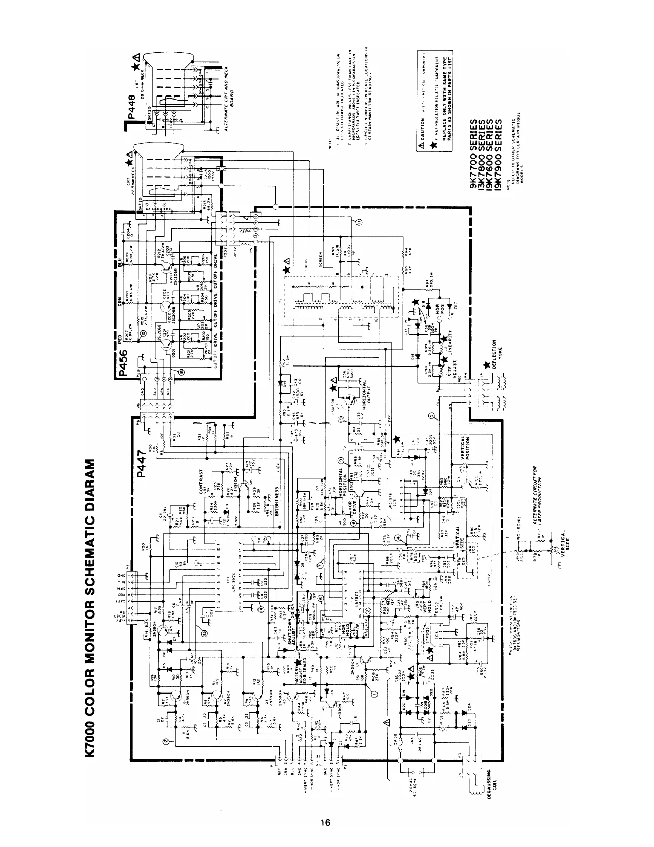
This page is a drawing, shown as the original scan.
FIG. 12 9661 33°9M
3) I ; 3 R2il : me {Fc ors BLU 18 q2zo2© & ES 2 G Nn Sos f FlL__ 5 BLUL J” Vv 9KG P456 smber
85X0221C vR2oi C20! vr202
RED
CUTOFF RED DRIVE P2ol CUTOFF DRIVE
VIEW OF COMPONENT SIDE
PC BOARD LAYOUT P456
FIG. 13 85X02!I7B C204 ©w.6.€.c. 1986
lOZUA RED
CUT OFF
(ks) Oreo P448 C205 9OZHA
a
SOZYUA
vOZHA
2022
£OSUA
ZOZKA R201 GRN R203. BLU
REO DRIVE CUTOFF GRN DRIVE CUT OFF BLU DRIVE
VIEW OF COMPONENT SIDE
PC BOARD LAYOUT P448
FIG. 14 LSA S 125VAC 8 A Rios Vee ow css
8 ae ied cus “ 2. J__T ]. ee p20 i coz ce
ty 4 Tres Ln con aM BSx02I6-OOE TF. ls con Rev MAIN PC BOARD LAYOUT
Riot
R102
FRONT CONTROL BOARD P485
R103
1° RED Cy.
GREEN
( ven
BLUE
Peo [|
BLU GRN RED w
S
BLACK
LEVEL FIG. 85X0170-A R104 o108
Swiot TEST VRI05 VERT POS VERT SIZE VR C) HORIZ POS RIOT
| 7 F bao FYE LOOT TTT -+fFRom vorimiarcern| 10 ~ DTACK 0 © A} co} tal | 9) of | ol we die ae 7 BLENTERG, LL CNTENG!| ENTENF om | | To 1710 3/10 fa
‘DRAWN_ (CHECKED, DESIGNED APPROVED]
This page reads as a drawing: its text was drawn rather than typeset, and comes out in fragments. See the original scan.
LOSWR
ron 1/10 [ DSH Tumzo15_ sf
| | Rom 3/10 u
LITE TTT €
8se
FROM 1/10 & 1/10 COSWR
FROM
1/10 COLRAM FROM COLOFF
LITT 8/10
y
TTT a FROM 1/10 Dornonwnaro
‘i a
= iG (it FROM 9/10 12 MHz. From Y SCWAIT. rom 5/10 WAT a DIACK To 1/10
A a FROM 1/10 FRCS. INA
- FY wo} 104 a} WH ea ad Gd
Ta
ITT SESS en ene onmte T ¥ Te 1/10, DTACK From
Figs Jin7e ER tros PSB Ot oT IED The
SAW NS. 1/10
A THLE
86612-A-3/10 DATE + DRAWN | CHECKED [DESIGNED |APPROVED|
Sars |
CAPCOM
Cc
i aE INGLE BROLEGTION Div Nee SHEET
T it TI DOT y | t m1. . OTT TT TTT. TTTTT TTT 245 it Rez lour iN +12V_FROM
a 18 10/10
Saw 4g Let | 35 1OD1x 4
GT 21 28C2120%4 Dies
Ret
FROM
>
bale efolslele
ATS ]N |] Sh9)
ES a g Ey ARSE Sa ely 4 &
Fy
spr 2p uP.
mlsfe-fo-| z & dy
o> bo foster &
Sy QR> exon <
S55 RRR 4] ‘ACL1. FROM 1/10 FLIPB To X.Y.Z v0
SERA i on wnemar a 4/10 A
DRAW NO,
86612-A -
; TW q
CELT Tr = THIF 1 Y
TTTN ~4
CTTTTTT TT rt T T = Y.X
FROM
4/10
8/10 10 6/10 to 6/10
CHHFLIP a
ny jes ” pe —__ce2 |, 2/40
VRAMCS. oe aE 7 | 86812- A -5/10 a hos
DATE. ‘DRAWM |CHECKED | DESIGNED APPROVED| ~ CAPCOM |” FO BNGLE PROTECTION Dit IN a) SHEET
+5
WON by} ro 7/10 FROM = 8/10 3 ‘DRAW NO. TITLE 86612- A -6/10 rN ATE (DRAWN) |CHEGKED DESIGNED APPROVED
t . COCO eer val SE | ff CAPCOM
NTS
t Ta 7 TT = = 30 BNGLE PROJECTION Dim IN = 1 SHEET 7
4 y , i | sivartiieienareed CHAS 5
VEEL TEP trei deirdre y
Portrrny
FROM
‘DRAW NO. A
V1
DATE
SCALE
NTS Ze 86612 - A -7/10 > [DRAWN [CHECKED [DESIGNED IAPPROVED i
PETTTI ei a-r [ sunnbirnnny rcumrivinttireralerd B
FROM
St eg ial Mao 14 al stopeltloys s
- 19] «¢]19} of © FROM6/10 CHEM | 4] 26 ABO 3] Bs
1710 aec7
CERPh rr
t COLOFF 8/
TOLOFE To
3A 6162
WSS 01/9 *f rn
a
nous Wows “| a DRAW NO. TE
3/10 TOLWE 856*2-A-8/10 ~ | DRAWN | CHECKED DESIGNED APPROVED] <J
DATE
i
This page reads as a drawing: its text was drawn rather than typeset, and comes out in fragments. See the original scan.
This page reads as a drawing: its text was drawn rather than typeset, and comes out in fragments. See the original scan.
This page reads as a drawing: its text was drawn rather than typeset, and comes out in fragments. See the original scan.
FROM 1/10 <2 a | DI 157K 4 TMM2063_ +5 < a k vec i=
| 2 vet |S ae t 7 ale
Al WON,
ols by
Ob woud
ous. wows
| 5 wows
duos
WASTT jumsan
Leev zav av ld
t adn
v z@ ¥
48A GOLA
ELISA Ly Ly ry Ay eye Hi
Zee a) Sales a 8 n q TFS ARTA] ajofoa| Xf} gs
in ermrrerinerh sPTITh) PUPTTETP PEPE ry rb bbe erry Vit of arf es fra fe]. lo
+0 EOGmaala VATANES |
Sa 86612 -A-x A G
Soe a EET SCRE aE r | | CAPCO) T 7 a eid TNGLE PEOIESTION OM Ne
A nowal
o1}~
FROM. TSMR 7H0| | zo 6oge L——~ 3 score | HO) x
ows wow |
FROM SCREHFT +5
q ITT | z ITTTT1 y 35841 D ‘6 sB3H_ TO be
t | PPPYT Try FROM, 1110 Oa RO 86612 - A-Y A . DATE. DRAWN [GHECKEDIDESIGNEDIAPPROVED| SCRE | rev | | COM 4 7 ry 7 = 7 TEE SCE a ee ET
TTT VTA TT rt val
a i
CAPCOM
DEsGNEDAPPROVED| SCR B
DRAW NO,
86612 -A-2 Tt LDRAWN [CHESKE: SHEET
This page reads as a drawing: its text was drawn rather than typeset, and comes out in fragments. See the original scan.
7 i. I TIT T. ft OTT T saree is > tH ans dab 5Ax i arya] ey Z 7 Ee I) eyqeyyaalala i
EI
EI
Ova 13/3 10 3/13 ta 10 3/3
747i al Le ve Age 7 & hak
FROM FROM
3/13 2/13 2/13 ~- 7 37 TRE Sa ea
This page reads as a drawing: its text was drawn rather than typeset, and comes out in fragments. See the original scan.
I i Tt v ;
U T 70 113,213 FROM FROM FROM 43,513 213 313
FROM
5/13 oelels
to 273 FROM 23 FROM 2/13 Al™
FROM 2/13 wy 7 Sat T a 7 30 ANGLE BROECTION
7 | x)
PEEL PEEL ELL Y | res bo ¥
O11
FROM
FROM 3/13 FROM 3/13 FROM3/13 to 5/3 FROM. “5 ee Var 2F. Vie FLIP Rom 1/13
B\0 a 1] 2c
3/13 C18 2 7
aialaels|
Pm ol
Way To 573 To 5/13 1 6/3 5/3
DRAW NO. “B43 aN
85512 DAE + ‘SCALE NTS DRAWN [CHECKED | DESIGNED APPROVED| TITLE
sd
—#f 2d = WIS +5 FROM V3 9K v2B f al
Vee}22—] oe rrom| V32B cnoHt& 103) V64B v2568 4g 32/1601 wo 373 | i
FROM ROM CT256
NTT HTT
T1 TOCOCOCe rr. ; | I! l2nl2o 19/18|1716) 15133112 86S100 “ey
Aude
86S10C0 10G s aE ea ok
FROM 4/13 OBHFLIPA FROM 1/13 ViB i
FRoMs/13 OBBMB 2} TeLR zi 1 63 2CtR | EA
FROM 5/13 OGM 2 FROM FROM 5/13 OBOM 7 103 Hee From 4/13 TRE
FLIP
re, [ [alee OBFLIPs
a, | ry Le f FROM a3 V18 T aoe earure aa: : = rT 6/3, 7/13 DRAW NO. 86612 -B
?
LITT TIT TTT = 5/13
mfsefn FS
FROM
5/13
{sf « foolonly | SP PRE offen
sofa} -sfe fo
| TMM20180 - 45/55 es +5 OE veces ato GNF i
gl he $86 3 ore O77]
a a 2orc7 1 54) B 5 Ao popl tho 2 33 we Se
i a 20TC 0/0} Foss ee
TULLE ECE ctr.
Es
5/73
| 5/13
B7eha. S ‘ OBFLIFY 22
_Jrrom_ | TSF
gore Of | ¥
ee oe a 36612 -B - 6/13 A DATE 7 DRAWN [CHECKED DESIGNED APPROVED| —— Fe CAPCOM
_+
TTT
This page reads as a drawing: its text was drawn rather than typeset, and comes out in fragments. See the original scan.
TATA Tr. 117 at DIT 2 one = SF TMM2063_ <5 ve nr 4e PX ar emaman aD wemere Q
g S34__ JAS HP) FOS gSHFLIP a
i gisvFur
& 4130 al PdISHS © p s A
i
BI
£6 HOU
£1/0b T - Ea} NOE BROIECTION co
FOLEEM Pree t Y theca FROM 1/13, 5a
i at
r fb po 873
TITLE 86512 -6 -9/13 A ‘DRAWN (CHECKED DESIGNEDIAPPROVED| SCR. i
aE I | | CAPCOM
siriariverrermerrnelr| = : is ONE PROJECTION om
“8 2725 & S6M
FRON
s3H | 913 SHFUPA rom 8/13 FLIPS FROM 1/13 |,.
COOL Tee eee = ; z 5 TEE PROECTION
TH
DL- 0100 CRE ea |
HPTL. 128 11/13 (INF V256Br0) cl TO5/13 T0213} -lany H256B 7 113; 113; 128 1 4 Rt vj L 32109733} 16 109/13 H1B 109/13} 7HB Nc OHB_NC 43HB_N.C 4H B_N.C 4CKB 10 4/13 5/13 3CKB_ 105/43
DRAW NO. 86612-B-11/13
TEC Tt +O Ter Three GND Fry og 4 COMPSYNC tf { GND vec No vec
GND 12 08 0 oH 12 43H 3 6No vec
g
o g i aH 14 GNO GNO
T vec 45 AB 40 HBL no
g vec 16 AB 9 vaLs 16 6No No 16 Ha
sca 7
= vt ae SCA S sca 3 49 SCR 4 GNO 18 H2
vec 18] ag? so el ae
vec 19 4B 6
lV LI NO ; 19 Ha vec 20 ABS SCA t [20 SND 20 GND
GND 24 By 7 22 | oBy 6 no 22 | BNO vec fas AB 4 GND at ack
LUT vec AB 3 vec 23 482 08 5 [ea] oa 6No 23 s2MHz By 3 24 oBu 2 GNO 24 GND
oe an ee ey ee Se
[=| vec 2a[ nat GNo 25 HPTL
vec 25 ACL 2
OTM COT 2. ee
DRAIN 86612 CN=1.CN-2.CN-3 TE SOP FLATCABLE . DATE - + [DRAWN [CHECKED] DESIGNED APPROVED] CONNECTOR LIST i —z = eZ | | CAPCOM r 7 i z ta i z 7D FNGLE PROJECTION] DIM IN =» | SHEET
TT
PARTS NAME
CR7E-S60A-3.56E : (HIROSE) oR 1468-056 -009 : (KEL )
COIN LOCK OUT 4
SP (+)
VIDEO BLUE
VIDEO GNO
TEST Sw
CTT TTT TTT TTT rr TTT Tite
JAMMA EDGE CONECTOR
DRAW NO. DATE
LEL we SCA ‘nT CAPCOM iN] OM IN [SHEET 7
LIMITED WARRANTY
CAPCOM, USA, INC. ("Seller’), warrants only to the initial purchaser of its products that the items listed below are free from defects in material and workmanship under normal use and service for the warranty periods specified:
A. Printed circuit boards (90) days B. Television monitor (30) days
No other parts of Seller's products are warranted.
Warranty periods are effective from the initial date of shipment from Seller to its authorized distributors.
Seller's sole liability shall be, at its option, to repair or replace products which are returned to Seller during the warranty periods specified, provided:
A. Seller is notified promptly upon discovery by buyer that stated products are defective.
B. Such products are properly packaged and then returned, prepaid to Seller's plant.
This warranty does not apply to any parts damaged during shipping or handling, or due to improper installation or usage, or alteration. Inno event shall Seller be liable for any anticipated profits, loss of profits, loss of use, incidental or consequenmtial damages or any other losses incurred by the customer in connection with the purchase of a CAPCOM USA, Inc. product.
(WARRANTY DISCLAIMER)
EXCEPT AS SPECIFICALLY PROVIDED IN A WRITTEN CONTRACT BETWEEN SELLER AND PURCHASER, THERE ARE NO OTHER WARRANTIES, EXPRESSED OR IMPLIED, INCLUDING ANY IMPLIED WARRANTIES OF MERCHANTABILITY OR FITNESS FOR A PARTICULAR PURPOSE.
This page carries no recoverable text. It is a drawing or a photograph. See the original scan.
WARNING
Federal law provides severe civil and criminal penalties for the unauthorized reproduction, distribution, or exhibition of copyrighted audiovisual works and video games.
The Federal Bureau of Investigation
investigates allegations of criminal copyright infringement.
1238-C Mountain View/Alviso Rd. Sunnyvale, CA 94089