18 Wheeler Parts and Operating Manual (July 1979)
18 Wheeler (set 1) (Midway, 1979) · Parts & Operating Manual · 48 pages · 29 sections · original scan
GAME NO. 653 JULY, 1979
MIDWAY’S
LE HEEUER
PARTS AND OPERATING MANUAL
FBIyHEELER
MIDWAY MFG. CO.
hd 10750 WEST GRAND AVENUE
~ FRANKLIN PARK, ILLINOIS 60131 U.S.A.
PHONE: (312) 451-1360 CABLE ADDRESS: MIDCO TELEX NO.: 72-1596
TABLE OF CONTENTS
PICTURE — GAME IN SHILL MODE
GENERAL INSTRUCTIONS & INFORMATION
SWITCH ADJUSTMENTS
NO. 653 - 18 WHEELER - PICTURE
PULLEY & STEERING WHEEL ASSEMBLIES
ACCELERATOR PEDAL ASSEMBLY
FLUORESCENT FIXTURE ASSEMBLY
GEAR SHIFT ASSEMBLY
OPTICAL SYSTEM ASSEMBLY
ADDITIONAL PARTS LIST
FRONT DOOR ASSEMBLY
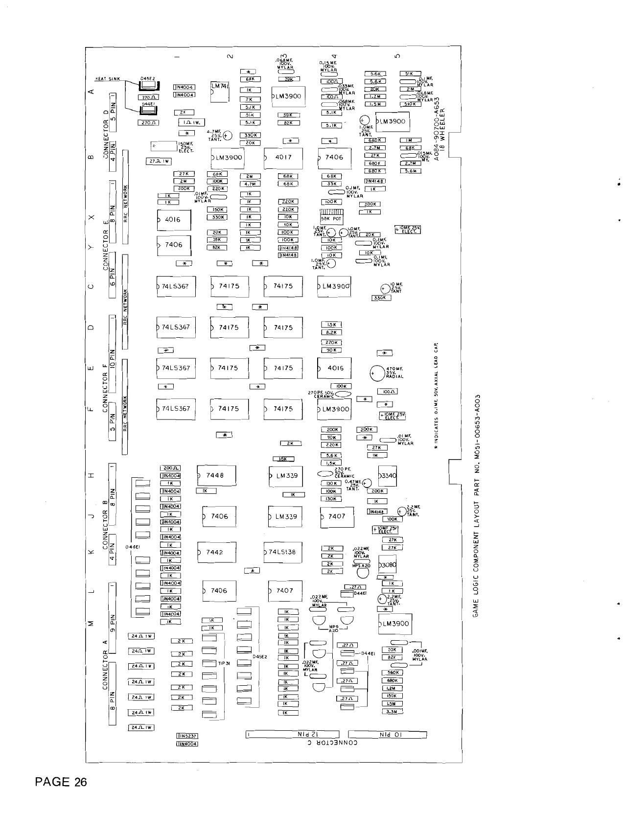
GAME BOARD COMPONENTS LAYOUT
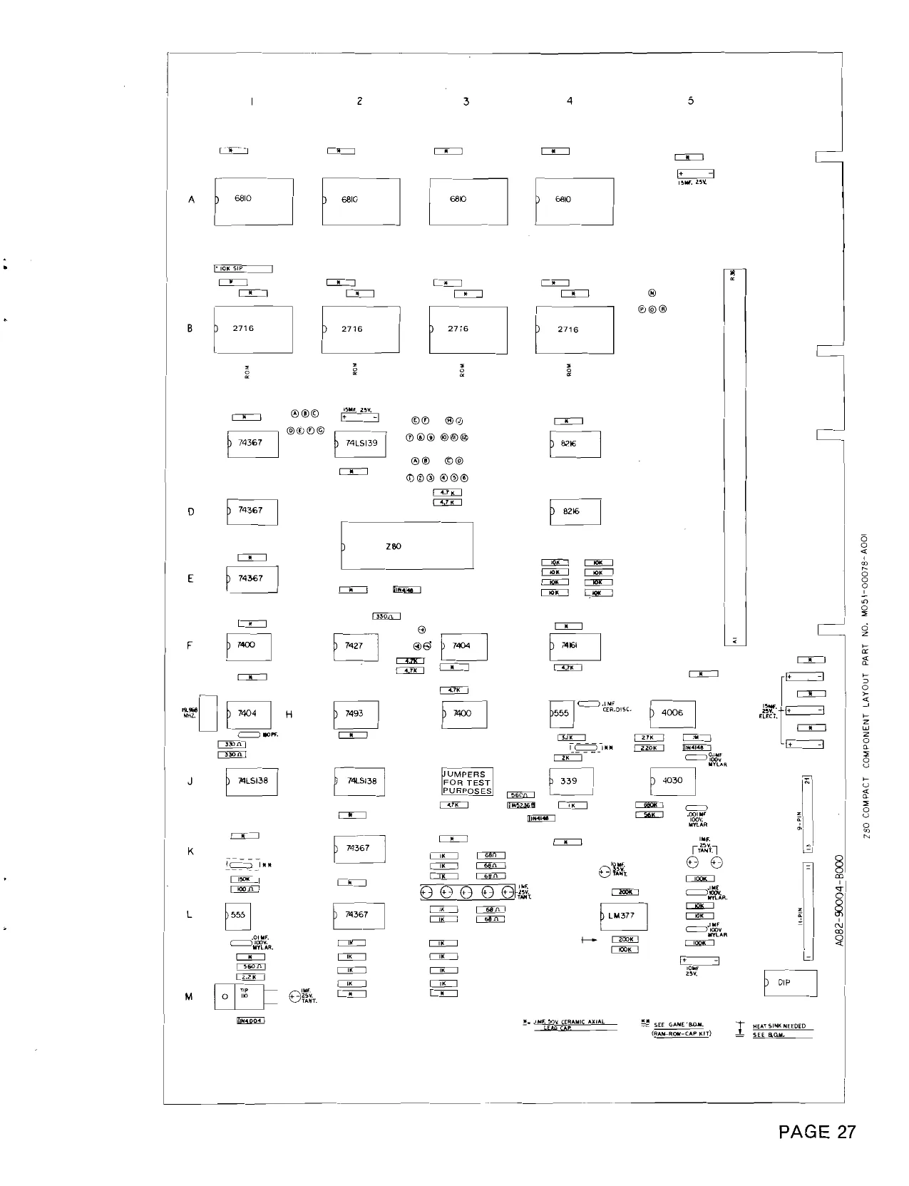
MOTHER BOARD COMPONENTS LAYOUT
POWER SUPPLY COMPONENTS LAYOUT
POWER SUPPLY SCHEMATIC
TRUCK SENSOR & LAMP DRIVER P.C. BOARDS
WIRE SCHEMATIC 18 WHEELER
GAME LOGIC SCHEMATIC 18 WHEELER
LOGIC SCHEMATIC 18 WHEELER
GAME LOGIC COMPONENT LAYOUT - B VERSION
GAME LOGIC SCHEMATIC - BVERSION
THIS GAME MUST BE GROUNDED. FAILURE TO DO
SO MAY RESULT IN DESTRUCTION TO ELECTRONIC COMPONENTS.
DEAR OPERATOR 18 WHEELER HAS A SHILL OR ATTRACT MODE WHICH IS ACTIVATED WHEN THE GAME IS NOT PLAYED FOR A PERIOD OF 20 MINUTES. THE SHILL MODE HAS PROVEN TO ATTRACT MORE PLAYERS DURING OUR LOCATION TESTS, AND WILL UNDOUBTEDLY DO THE SAME FOR YOU.
18 WHEELER
DIAGNOSTICS/ALIGNMENTS/SOUNDS
GAME TEST
- Place gear shift in neutral position.
- Place switch #8 (located on Mother Board) in “ON” position.
- Close tilt switch located on coin door assy.
The program goes through a RAM/ROM test.
BAD RAM
If score display reads O 1 RAM 4 located at A-1 is bad {f score display reads O 2 RAM 3 located at A-2 is bad If score display reads 0 3 RAM 2 located at A-3 is bad If score display reads OQ 4 RAM 1 located at A-4 is bad
BAD ROM
If score display reads 8 1 ROM 1 located at B-1 is bad If score display reads 8 2 ROM 2 located at B-2 is bad If score display reads 8 3 ROM 3 located at B-3 is bad If score display reads 8 4 ROM 4 located at 8-4 is bad
lf the RAMs and ROMs check out as good, the program goes through countdown of the display
9876543210 8765432101
g123456789
and ends the test by writing 8 8 8 8 8888 8 8 __ onthe displays.
At the end of the display test, the program goes into lamp test. This is done by switching half of the lamps on at one time for 2-3 seconds and then switching the other half of the lamps on.
The display will continue to read 8’s and lamps will continue to switch on and off until switch #8 (located on Mother Board) is returned to “OFF” position and tilt switch is closed.
GENERAL INSTRUCTIONS FOR “18 WHEELER”
INSTALLATION 1, Remove shipping cleats located on the bottom of the cabinet.
- Install four (4) provided leg levelers to bottom of cabinet and level cabinet.
- The power is controlled by a switch located on top of the cabinet. Plug into A.C. only, 115 volts, 60 cycles. In low line areas (105 volts or less), a boost in the output voltage of the transformer may be obtained by removing the wire from the 115 volt tap of the transformer and rewiring it to the 105 volt position.
LINE VOLTAGE SAFETY SWITCH A line voltage safety switch has been provided for your protection. It is located on the right rear side of the cabinet in the lower back door area. When the door is removed, it opens the circuit to the line voltage. To restore power (when servicing), pull switch fully out.
TO REMOVE CONTROL SHELF FOR SERVICE 1, Open coin door, Unlatch 3 clamps, 2 on left side, 1 on right front side of cabinet.
- Disconnect control shelf connector. 4 Remove wing nut, washer and steering cable from steering wheel assy.
MASTER VOLUME CONTROL POT Located on Game Logic Board (P.C. A084-90700-A653) and controls the volume of all sounds and may be varied as desired, by rotating pot control.
COIN, TIME, EXTENDED PLAY AND TEST SWITCHES located on Mother Board (P.C. A082-90400-B000) and may be adjusted as indicated on separate instructions in back box area.
SERVICE BUL im Ia |2
GAME: 18 Wheeler SUBJECT: Projection Lamp & Air Circulation
- All games will be shipped with projection lamp removed and stored in cash box area. (or rear of game)
- When installing lamp, insert completely in lamp socket for proper operation.
- A spare projection lamp will be shipped with each game.
- Do not set game flush against a wall. For proper air circulation and longer lamp life, leave three to four inches of space behind the game.
PAGE 2A
TO ALIGN ACCELLERATOR ENCODER
1.
2. Remove three (3) bolts & two (2) wood screws on forward portion of accelerator/brake pedal assy. at front of game and pull assy. forward. Place gear shift in 1st gear position. Place switch #8 (located on Mother Board) in “ON” position. Close tilt switch located on coin door assy.
The program continuously monitors the accellerator encoder and displays a number on the score display.
Loosen the two set screws on the encoder gear and rotate the encoder shaft until the score display reads “ 00. When number “00” is reached, the horn sound is turned on. if desired, the horn sound may now be turned off by placing gear shift in neutral position. Tighten two set screws on encoder gear to encoder shaft. Verify that the score display still reads “00" and the horn sound is turned on when in 1st gear position. Return switch #8 (located on Mother Board) to “OFF” position. Close tilt switch to go into game mode.
BRAKE CAM & SWITCH ADJUSTMENT
CAM_HIGH_ SIDE (SWITCH TO MAKE)
(SWITCH OPEN)
Position brake cam as per sketch above with brake pedal up.
TO ALIGN THE ROAD DISC ENCODER
- Place gear shift in 2nd gear position.
- Place switch #8 (located on Mother Board) in “ON” position.
- Close tilt switch located on coin door assy.
4.
12. 13. 14. Loosen two set screws on white plastic gear at the rear of the projector disc and disengage large gear from small gear by sliding large gear to rear of shaft. Next, loosen two set screws on cam assy. to free cam from encoder shaft. See Sketch A. Remove two short mounting brackets holding Game Logic and Mother Board printed circuit assy. in place. Pull printed circuit assy. out of cabinet as far as slack in cable will allow, This will provide access to the disc drive motor which is located on the front surface of the projector pan assy. in the upper left hand corner. Carefully \ift motor off disc using provided lever and rotate disc until number “ 1", on the outside of the disc, is exposed on the right side of the projector pan. See Sketch A. Carefully position the disc until the pick-up cargo score area is in line with the lower optical sensor. See Sketch B. This may be seen in the \ower front reflector mirror. Release motor to lock road dist in position. Rotate small pinion gear on encoder shaft until crash sound is heard. Rotate small pinion gear on encoder shaft in opposite direction: until another crash is heard. Position pinion to approximately split travel between crashes. Carefully engage white plastic gear (with set screw up, see Sketch A) with the pinion gear and tighten set screws. The score display should now read “37”. If any other number is displayed, loosen set screws on white plastic gear and repeat step 10 and 11. Reassemble cam in position shown in Sketch A. Note this position does not have to be precise. Adjust leaf switch for proper operation. Return switch #8 (located on Mother Board) to “OFF” position and close tilt switch to go into game mode.
IN DOCK SCORE AREA
a PROYECTOR, | RAN yi CAM ASS'Y. Sesion psc
a SHAE T JABS
wire LOWER SENSOR
SKETCH A SKETCH B
SQUND AND INPUT SWITCH DIAGNOSTICS
1, 2. Place gear shift in neutral position. Place switches #7 and #8 (located on Mother Board) in “ON” position.
- Close tilt switch located on coin door assy. If coin switch is closed Bell will sound If start switch is closed Crash will sound
If 1st gear switch is closed Engine will sound If shift is in gear & accelerator is depressed Engine will rev up If 2nd gear switch is closed Horn will sound If 3rd gear switch is closed Bell will sound twice If reverse gear switch is closed Harn will sound twice
If brake switch is closed Air brake will sound
Return switches #7 and #8 (located on Mother Board) to “OFF” position.
- Close tilt switch to go into game mode.
Focus
1, Place switch #8 (located on Mother Board) in “ON” position. Close tilt switch located on coin door assy. Remove two short mounting brackets holding Game Logic and Mother Board printed circuit assy. in place.
- Pull printed circuit assy. out of cabinet as far as slack in cable will allow. This will provide access to the lens assy. which is located on the front surface of the pan assy. on the lower left hand side.
- Loosen two thumb screws on lens bushing and move lens in or out to abtain the sharpest image of the road at the bottom half of the screen when viewed from rear of game.
- Retighten thumb screws and remount printed circuit assy. Return switch #8 (located on Mother Board) and close tilt switch to go into game mode. eS
STEERING WHEEL CABLE AND PROJECTOR PAN ALIGNMENT
- Place switch #8 (located on Mother Board) in “ON” position.
- Close tilt switch located on coin door assy.
- Viewing up through coin door opening, turn steering wheel until cable pivot stop assy. is centered hetween two stop brackets. See sketch below.
| STOP ASSY.
- From sear of cabinet, remove spring from pivot channel located at the bottom of the cabinet.
1.
12, Making sure the steering wheel cable is drawn over (2) pulleys on the side of the cabinet, insert table through adjusting block on pivot channel leaving about three (3) inches of cable through the left side of the adjusting block. Do not tighten cap screw at this time. Remave two short mounting brackets holding Game Logic and Mother Board printed circuit assy. in place. Pull printed circuit assy. out of cabinet as far as slack in cable will allow. This will provide access to the disc drive motor which is located on the front surface of the projector assy. in the upper left hand corner. Carefully lift motor off disc using provided lever and rotate disc until white scoring area is in line with the truck cab pivot screw at top of screen. Pivot projector pan assy. until white scoring area is centered from left to right about truck cab pivot screw. Take up all slack in steering wheei cable by pulling cable through adjusting block until cable is taught. Tighten cap screw on adjusting block and replace spring. Loosen two set screws on truck pivot. {located above projector pan unit under screen). Align truck pivot in center of slotted cut-out in screen, being careful to position truck pivot bracket 1/4” below screen and tighten set screws. Replace printed circuit board assy. Return switch #8 (located on Mather Board) to “ON” position and close tilt switch to go into game mode.
SWITCH ADJUSTMENTS
COIN
sw. 1 sw. 2
| 1 COIN= 1 PLAY | ON | ON |
| 1 COIN =2 PLAYS | OFF | ON |
| 2 COINS = 1 PLAY | ON | OFF |
| 2 COINS = 3 PLAYS | OFF | OFF |
TIME-EXTENDED PLAY
| TIME | EXT. PLAY | SCORE | SW. 3 | sw.4 | SW. 5 | sw. 6 |
| 60 SEC. | 20 SEC. | 4,000 | ON | ON | ON | ON |
| 60 SEC. | 30 SEC, | 8,000 | OFF | ON | ON | ON |
| 80 SEC. | 15 SEC. | 8,000 | ON | OFF | ON | ON |
| 60 SEC. | 30 SEC. | 10,000 | OFF | OFF | ON | ON |
| 70 SEC. | 20 SEC. | 6,000 | ON | ON | OFF | ON |
| 70 SEC. | 30 SEC. | 9,000 | OFF | ON | OFF | ON |
| 70 SEC. | 20SEC. | 9,000 | ON | OFF | OFF | ON |
| 70 SEC. | 30SEC. | 12,000 | OFF | OFF | OFF | ON |
| 80 SEC. | 20 SEC. | 8,000 | ON | ON | ON | OFF |
| 80 SEC. | 30 SEC. | 12,000 | OFF | ON | ON | OFF |
| 80 SEC. | 20SEC. | 12,000 | ON | OFF | ON | OFF |
| 80 SEC. | 30 SEC. | 18,000 | OFF | OFF | ON | OFF |
| 90SEC. | 20 SEC. | 10,000 | ON | ON | OFF | OFF |
| 90 SEC. | 30SEC. | 15,000 | OFF | ON | OFF | OFF |
| 90 SEC. | 20 SEC. | 18,000 | ON | OFF | OFF | OFF |
| 90 SEC. | 30 SEC, | 20,000 | OFF | OFF | OFF | OFF |
TEST -PLAY
sw.7 Sw. 8
| RAM/ROM — TEST | ON | ON » |
| GAME MODE | OFF | OFF |
MOSt -00653-A010
NO. 653 — 18 WHEELER — PICTURE
© ® © ©
MIDWAY MFG. CO. ABALLY COMPANY
NO. 653 — 18 WHEELER — PICTURE
ORDER BY PART NUMBER ONLY
0653-00911-01SC 0537-00903-0023 0537-00903-0042 0629-00902-0500 0653-00910-0000 A653-00038-0000 A084-91326-B653 0017-00031-0029 0017-00003-0226 A084-91325-C653 0653-00158-00XF 0017-00102-0079 0017-00104-0013 0017-00103-0005 A653-00048-0000 0653-00902-00XF A090-00020-2001 0017-00003-0102 0090-00002-02GR 0017-00101-0555
0017-00009-0393 0917-00003-0187 0017-00101-0642 A653-00028-0000 0017-00102-0048 0017-00103-0026
0653-00908-00XF
A653-00052-0000 0653-00148-0000 0653-00149-0000 0605-00104-01B0 0017-00009-0009 0603-00131-00XF ITEM| PART NO. DESCRIPTION DISPLAY PLEX GLASS CHANNEL - 27%” GLASS CHANNEL - 18%4”’ (2 REQD.) GLASS LIFT CHANNEL - 27-7/8” PLEXIGLASS SCREEN TRUCK SYSTEM ASSY. TRUCK LIGHTS P.C. BRD. ASSY. MIN. WEDGE SOCKET (8 REQD.) 6.3V WEDGE LAMP (8 REQD.) L.E.D. DISPLAY BRD. ASSY. CONTROL PANEL PLATE #6-32 x 144 CARRIAGE BOLTS (6 REQD.) #6 PERIPHERY WASHER (6 REQD.) #6-32 HEX NUT (6 REQD.) GEAR SHIFT ASSY. STEERING WHEEL DOUBLE ENTRY COIN DOOR COIN METER (MOUNTED ON DOOR) COIN DOOR FRAME #6-32 x 5/16 BLK. HEX HD. S.M.S. (3 REQD.) (MOUNTS DOOR TO FRAME) SPEAKER GRILL & HARDWARE 6 x 9 SPEAKER - 8 OHM, 9W #8-32 x 1% CARRIAGE BOLTS (4 REQD.) ACCELERATOR PEDAL UNIT ASSY. LEG LEVELERS (4 REQD.) LEG LEVELER NUTS (4 REQD.)
NOT SHOWN LIST 1/8’ MIRROPANE MIRROR - 27-7/8x15-1/2x1/8” (UPPER) 4’? MIRROPANE MIRROR ASSY. - 27-7/8x15-7/8x 1/4” LOWER 1/4” MIRROPANE RETAINER UPPER 1/4” MIRROPANE RETAINER GLASS LOCK BRKT. (2 REQD.) TURNBUTTONS (2 REQD.) STRIKE (3 REQD.)
MIDWAY MFG. CO. A BALLY COMPANY PAGE 9
NO. 653 — 18 WHEELER — PICTURE
ORDER BY PART NUMBER ONLY ffeM|_rart wo. | DESCRIPTION 0017-00009-0033 | BASSICK CLAMP (3 REQD.) 0017-00101-0028 | #8 x 3% HEX HD. W/W BLK. SCR. (8 REQD.) 0653-00907-0000 | BACK-UP DISPLAY CARDBOARD 0653-00914-00XF | SCORE MASK CARDBOARD 0653-00913-0000 | CARDBOARD BACK-UP FOR ‘4’? MIRROPANE 0653-00912-0000 | CARDBOARD CABLE COVER-UP 0586-00036-0000 | ON-OFF SWITCH 0567-00106-0100 } SWITCH MTG. PLATE 0017-00101-0025 | #8 x % HEX HD. WD. SCR. (2 REQD.) A653-00029-0000 | DISPLAY INSERT ASSY. 0017-00003-0219 | #194 WEDGE LAMP - 14V (5 REQD.) A653-00032-0000 | BACKGROUND INSERT ASSY. 0017-00003-0226 | #444 WEDGE LAMP - 6.3V (27 REQD.)
NOTES
This space is provided for personal notes
MIDWAY MFG. CO. ABALLY COMPANY
NO. 653 — 18 WHEELER — PULLEY & STEERING WHEEL ASSEMBLIES
MIDWAY MFG. CO.
ABALLY COMPANY
NO. 653 — 18 WHEELER — PULLEY & STEERING WHEEL ASSEMBLIES
ORDER BY PART NUMBER ONLY
A653-00001-0000 0653-00902-00XF A653-00043-0000 0017-00007-0082 0017-00007-0077 0017-00101-0344 0017-00102-0005 0653-00917-0000 0653-00918-0000 0653-00150-0000 0017-00100-0109 0017-00009-0088 A653-00046-0000 0017-00042-0168 0017-00042-0022 0017-00042-0097 A653-00044-0000 0653-00153-0000 0010-00594-0000 0017-00104-0044 0017-00100-0050 0017-00100-0025 0017-00100-0031 | 0017-00104-0090 A653-00047-0000 0653-00160-0000 0017-00104-0023 0017-00103-0070 0017-00102-0019 0017-00104-0014 0017-00103-0018
A653-00050-0000 0653-00166-0000 0017-00101-0558 0017-00042-0206 0017-00100-0031 0017-00101-0027 0017-00104-0080 0017-00104-0005 DESCRIPTION
HORN BUTTON ASSY. STEERING WHEEL SHAFT & HUB ASSY. 1/8 x 1-3/8 ROLL PIN 1/8 x 3/4 ROLL PIN 1/4 - 20 x 1-1/4 SOCKET CAP SCREW (3 REQD.) 1/4 - 20 x 5/8 SOCKET CAP SCREW (4 REQD.) STEERING POST SHIELD NYLON WASHER TOP PLATE 3/4 “E” - RING BEARING ASSY. STEERING BRKT. WELDMENT 3/4 NYLINER 1/4 NYLINER (2 REQD.) 1/2 NYLINER GEAR ASSY. CLUTCH WASHER COMPRESSION SPRING 3/4 x 1/2 x 1/16 STL. WASHER 1/2 “E” - RING 1/4 “E” - RING 5/16 ‘‘E”’ - RING RUBBER STOP WASHER PIVOT STOP ASSY. STEERING CABLE STL. WASHER #10 - 32 WING NUT 1/4 - 20 x 1-1/2 CARRIAGE BOLTS (4 REQD.) 1/4 PERIPHERY WASHER (4 REQD.) 1/4 - 20 HEX NUT (4 REQD.)
PULLEY ASSEMBLY PULLEY BRKT. ASSY. (2 REQD.) CABLE GUIDE (2 REQD.) #6 - 32 x 5/16 S.T.M.S. (4 REQD.) PULLEY (2 REQD.) 5/16 ‘‘E’’ RING (2 REQD.) #8 x 3/4 HEX HD. WD. SCREWS (4 REQD.) 1-1/4 x 3/4 x 1/16 STL. WASHER 1/4 SPLIT LOCKWASHER (4 REQD.)
MIOWAY MFG. CO. A BALLY COMPANY PAGE 13
NO. 653 — 18 WHEELER — BRAKE & ACCELERATOR PEDAL ASSY.
MIDWAY MFG. CO. A BALLY COMPANY
NO. 653 — 18 WHEELER — BRAKE & ACCELERATOR PEDAL ASSY.
ORDER BY PART NUMBER ONLY ITEM PART NO. DESCRIPTION
OMAN OA BwWHD = 0653-00105-0000 0610-00002-0000 0653-00104-0000 0017-00101-0597
0610-00004-0000 A653-00003-0000 0011-00100-0600 0017-00103-0011 A082-91101-B000 0583-00723-0000 0017-00100-0050 0017-00101-0308 A653-00067-0000 017-00041-0015 A653-00053-0000 0020-00202-0000 0017-00101-0529 0610-00003-0000 0017-00100-0031 0010-00228-0000 0017-00100-0025 0017-00101-0785 0653-00734-0000 CONTROL MTG. BRKT. ACCELERATOR PEDAL & HINGE ASSY. (2 REQD.) ACCEL. PEDAL COVER PLATE #8 x 5/16 HEX HD. S.T. SCR. (17 REQD.) MTG. BRKT. ASSY. - ACCELERATOR MTG. BRKT. ASSY. - BRAKE PIVOT POST (2 REQD.) #10 - 32 LOCK NUT (2 REQD.) ANGLE ENCODER SWITCH (1 REQD.) GEAR (1 REQD.) 1/2” E - RING (2 REQD.) #8 - 32 x 3/16 SOCKET SET SCREW (2 REQD.) SWITCH CAM ASSY. RUBBER BUMPER (2 REQD.) BRAKE SW. ASSY. SWITCH PLATE #5 - 40 x 7/8 R.H.M.S. (2 REQD.) GEAR & LEVER ASSY. (2 REQD.) 5/16” E - RING (2 REQD.) SPRING (2 REQD.) 1/4” E - RING (2 REQD.) 1/4 - 20 x SLT. EXT. PAN HD. S.T.M.S. STOP -ENCODER LIMIT
MIDWAY MFG. CO. A BALLY COMPANY PAGE 15
NO. 653 — 18 WHEELER — FLUORESCENT FIXTURE ASSY.
MIDWAY MFG. CO. A BALLY COMPANY nee.
NO. 653 — 18 WHEELER — FLUORESCENT FIXTURE ASSY.
ORDER BY PART NUMBER ONLY feo] Part No. | DESCRIPTION 0017-00003-0095 0017-00021-0005 0017-00101-0573 0017-00031-0036 0017-00003-0019 0017-00101-0528 0017-00021-0079 0017-00101-0555 0017-00003-0026 0017-00101-0017 A653-00054-0000 0017-00041-0013 ON A nhowond 18” FLUORESCENT BLACK LIGHT FLUORESCENT LOCKS (2 REQD.) #6 - 32 x 1/2 R.H.M.S. (2 REQD.) FLUORESCENT SOCKET (2 REQD.) STARTER #5 - 40 x 3/4 R.H.M.S. (2 REQD.) STARTER HOLDER #6 x 5/16 HEX HD. S.M.S. (2 REQD.) BALLAST #6 x 1/2 BLK. HEX HD. W/W S.M.S. (3 REQD.) FLUORESCENT BRACKET ASSY. GROMMET (2 REQD.)
MIDWAY MFG. CO. pages A BALLY COMPANY
NO. 653 — 18 WHEELER — GEAR SHIFT ASSEMBLY
MIOWAY MFG. CO. A BALLY COMPANY
NO. 653 — 18 WHEELER — GEAR SHIFT ASSEMBLY
ORDER BY PART NUMBER ONLY ITEM| PART NO. DESCRIPTION
WOONONA AWNH 0017-00009-0435 A653-00041-0000 0653-007 26-0000 0017-00100-0021 0653-00178-0000 0653-00924-0000 0653-00727-0000 0017-00103-0049 A653-00007-0000 0653-00705-0000 0017-00042-0023 0017-00100-0037 0017-00101 -0652
0653-00156-0000 0653-00170-0000 0017-00101-0796
0653-00110-0000 0010-00255-0000 0653-00163-00XF 0653-00916-0000 0017-00006-0052 0653-00113-0000 0653-00109-0000 0017-00041-0015 A653-00042-0000 0017-00101-0599 0653-00162-0000 A653-00005-0000 A653-00006-0000 0091-00119-0000 0020-00202-0000 0017-00101-0528 0017-00102-0071 0017-00104-0046 0017-00103-0027
0653-00107-0000 0653-00176-0000 0653-00175-0000 0017-00101-0598 KNOB GEAR SHIFT LEVER & SW. ACTIVATOR ASSY. SPRING PIN 7/32”’ ‘‘E”’ RING (2 REQD.) WASHER PLATE (2 REQD.) SHAFT ADAPTOR GIMBEL PIN (2 REQD.) 5/16 - 18 HEX NUT (2 REQD.) PIVOT ASSY. PIVOT PIN NYLINER (2 REQD.) 3/8” “E’’ RING (2 REQD.) #10 - 32 x 3/8’? SLOT. PAN HD. EXT. S.E.M.S. (16 REQD.) U-BRACKET SPRING PLATE #10 - 32 x 3/4’? SLOT. PAN HD. EXT. S.E.M.S. (2 REQD.) DETENT BRKT. SPRING (2 REQD.) SUPPORT GEAR PLATE BALL BEARING HOUSING DETENT SPRING RUBBER BUMPER (4 REQD.) SWITCH MTG. BRKT. & LEG ASSY. e REQD.) #8 - 32 x 3/8 SLOT. HEX HD. S.E.M.S. (6 REQD.) SWITCH MTG. DEVICE (2 REQD.) SWITCH ASSY. - RIGHT (2 REQD.) SWITCH ASSY. - LEFT (2 REQD.) BACK UP STRIP SWITCH PLATE (4 REQD.) #5 - 40 x 3/4”” PAN HD. M.S. (8 REQD.) 5/16 - 18 x 1-1/2’? CARRIAGE BOLTS (4 REQD.) FLAT WASHER (4 REQD.) 5/16 - 18 ELASTIC STOP NUT (4 REQD.)
NOT SHOWN LIST SLIDE DISC SWITCH MTG. BRACE PROTECTION PLATE #8 - 32 x 5/16”’ §.T. SLT. HEX HD. M.S. (2 REQD. FOR ABOVE BRACE & 2 REQD. PLATE)
MIDWAY MFG. CO. A BALLY COMPANY PAGE 19
NO. 653 — 18 WHEELER — OPTICAL SYSTEM ASSEMBLY
MIDWAY MFG. co.
NO. 653 — 18 WHEELER — OPTICAL SYSTEM ASSY.
ORDER BY PART NUMBER ONLY
A653-00024-0000 0040-00617-0000 A653-00016-0000 A653-00012-0000 0017-00101-0086
0010-00258-0000 0653-00701-0000 0017-00041-0051 0017-00101-0305 A653-00017-0000 0017-00100-0031 0010-00254-0000 0653-00900-0000 0653-007 18-0000 0017-00101-0085
A653-00013-0000 0017-00101-0605 0017-00101-0596
0017-60103-0061 A653-00011-0000 A653-00023-0000 0067-011XX-XXFX 0017-00101-0599
0017-00003-0237 A653-00070-0000 0653-00188-0000 A653-00018-0000 0017-00104-0094 0653-00921-0000 A653-00055-0000 0017-00101-0308 0017-00042-0093 A653-00064-0000 0653-00172-0000 A760-00044-0000 0020-00202-0000 0017-00101-0527 ffi] rato. | ___ DESCRIPTION PAN & HUB ASSY. D. C. MOTOR 12V, 16 R.P.M. MOTOR MOUNT ASSY. SUPPORT BRKT. ASSY. #8 x 5/16 SLT. HEX WASHER HD. S.M.S. (16 REQD.) 3/4” LG. SPRING PULLEY - DRIVE DRIVE TIRE - 2” O.D. x 1-1/2” LD. x 1/4” #6 - 32 x 3/8 SET SCREEN (4 REGD.) MOTOR PIVOT BRKT. & STUD ASSY. 5/16 E - RING (2 REQD.) SPRING LENS RETAINER OBJECTIVE LENS LENS HOLDER #6 x 5/16 SLT. HEX WASHER HD. S.M.S. (12 REQD.) OBJECTIVE LENS MTG. ASSY. #8 - 32 x 3/8 THUMB SCREW M.S. (2 REQD.) #8 - 32 x 1/2 SLT. HEX HD. WASHER M.S. (5 REQD.) #8 - 32 HEX LOCK NUT (2 REQD.) CONDENSOR LENS ASSY. HEAT SHIELD & CONDENSOR LENS ASSY. INDUCTOR - 125mh, .55A., 60HM #8 - 32 x 3/8 SLT. EXT. HEX M.S. S.E.M.S. (4 REQD.) Lor CRT PROJECTOR LAMP - 120V, 300W - CZA-CZS SOCKET & BRACKET ASSY. AIR DEFLECTOR HUB & SHAFT ASSY. - SCENERY DISC NYLON WASHER GEAR REWORK HUB & CAM ASSY. - 180° #8 - 32 x 3/16 SET SCREW (4 REQD.) NYLINER ENCODER & PINION ASSY. SWITCH BRACKET SWITCH ASSY. SWITCH PLATE #5 - 40 x 5/8 SLT. RD. HD. M.S. (2 REQD.)
MIDWAY MFG. CO. A BALLY COMPANY
NO. 653 — 18 WHEELER — OPTICAL SYSTEM ASSEMBLY
ORDER BY FART NUMBER ONLY jiw| Part No. | DESCRIPTION 0017-00009-0454 | FAN - 10 BLADE - 4” DIA. 0017-00003-0236 {| A. C. MOTOR 110V. 0653-00129-0000 | FAN MOTOR PLATFORM 0017-00103-0005 | #6 - 32 HEX NUT (2 REQD.) 0017-00042-0204 | PLASTIC SPACER (2 REQD.) 0017-00101-0583 | #6 - 32 x 1-1/4 SLT. RD. HD. M.S. (2 REQD.) 0653-00717-0000 | PIVOT ROD
NOT SHOWN LIST 0010-00257-0000 | EXTENSION SPRING - BASE - 6-1/4”’ LG. A653-00020-0000 | BEARING ASSY. - BASE A653-00021-0000 | UPPER BEARING SUPPORT ASSY. 0653-00901-00SC | SCENERY DISC 0653-00142-0000 | PROJECTOR LIGHT SHROUD 0653-00138-0000 | PROJECTOR SHROUD CAP
PAGE 22 bstentes Mentha co,
NO. 653 — 18 WHEELER — ADDITIONAL PARTS LIST
ORDER BY PART NUMBER ONLY
TEM! PART NO. DESCRIPTION
A097-00001-0000 | LOCK ASSY. (1 UPPER, 1 LOWER) 0618-00117-00ZN ; VENT SCREEN (1 UPPER, 1 LOWER) NEXT FOUR ITEMS FOR 1ST 250 GAMES COIN BOX COIN BOX COVER ASSY. COIN BOX GUIDE BRACKET ASSY. COIN BOX GUIDE BRACKET NEXT FOUR ITEMS AFTER THE 250TH GAME COIN BOX ASSY. COIN BOX COVER ASSY. COIN BOX SIDE CHANNEL COIN BOX COVER #8 - 32 x 1-1/2’? CARRIAGE BOLTS (4 REQD.) SAFETY INTERLOCK SWITCH SWITCH BRACKET #8 x 1/2’? HEX HD. W/W S.M.S. (2 REQD.) COIN DROP CHUTE ASSY. GAME LOGIC BOARD ASSY. MOTHER BOARD ASSY. - Z80 COMPACT TRANSFORMER BOARD ASSY. POWER SUPPLY ASSY. SENSOR P.C. BOARD ASSY. (TRUCK) SENSOR P.C. ADJ. & SUPPORT BRKT. P.C. SUPPORT BRACKET - 12’ (3 REQD.) P.c. SUPPORT BRACKET - 2-1/2’ (4 REQD.) BLACK SHIELD 16 x 28-7/8 - UNDER CONTROL SHELF INSULATOR 9 x 5-1/2”? - TRANSFORMER INSULATOR 3 x 3-3/4’' - SENSOR P.C. 0653-001 39-0000 A653-00026-0000 A653-00025-0000 0653-001 17-0000
A653-00068-0000 A653-00069-0000 0653-00182-0000 0653-001 83-0000 0017-00101-0642 0017-00003-0225 0625-00133-0000 0017-00101-0025 A653-00022-0000 A084-90700-A653 A084-90004-B653 A653-00065-0000 A084-90406-C760 A084-91334-A653 0653-001 41-0000 0624-00902-0100 0624-00902-0300 0653-00920-0000
0653-00922-0000 0653-00923-0000
TRANSFORMER ASSY. TRANSFORMER 120V, 60 CYCLE FUSE BLOCK FUSE - 3A FUSE - 5A LINE CORD MT00-00075-0000 0720-00001-0300 0017-00003-0006 0017-00003-0169 0017-00003-0064
MIDWAY MFG. CO. PAGE 23 A BALLY COMPANY
NO. 653 — 18 WHEELER — FRONT DOOR ASSY.
VARIATIONS ARE DEPENDANT ON
MIDWAY‘S BASIC COIN DOOR,
YOUR PARTICULAR GAME.
NOTE:
NO. 653 — 18 WHEELER — FRONT DOOR ASSY.
ORDER BY PART NUMBER ONLY ITEM| PART NO. DESCRIPTION 0090-00902-0000 DRESS PLATE 0090-00902-0100 DRESS PLATE (W/O PRESS BUTTON TO START GAME) #6 - 32 x 1/4 CARRIAGE BOLT (2) COIN ENTRY PLATE (25¢) PLASTIC START BUTTON COMPRESSION SPRING DOOR ASSY. DOUBLE ENTRY DOOR LOCK & KEY WITH SCREW & NUT DOUBLE DOOR FRAME 421 N.S. CAM DOOR SWITCH SWITCH BACKUP PLATE #5 - 40 x 3/4’? LNG. M.S. 25¢ WINDOW COIN PLEX RETAINER SPLIT LOCK WASHER KEY HOOK #6 - 32 HEX NUT SW. PLATE & OILLITE ASSY. “E” RING SWITCH TOP & BTM. COIN CHUT W/BRKT. ASSY. #8 - 32 x 5/16 SCREW SPRING PIVOT POST SPRING ACCEPTOR FRAME ASSY. REJECTOR LEVER “E” RING COIN GUIDE MTG. BRACKET COIN GUIDE ASSY. #6 - 32 x 5/16 SCREW COIN SWITCH TRIP WIRE PUSH-ON RING (BIK) #4 - 36 x 3/4 SCREW SWITCH BRKT. - DOOR TILT 0017-00101-0552 0090-00117-03XF 0090-00906-0000 0010-00007-0000 0090-00013-0200 0017-00005-0050 0090-00002-02BR 0017-00005-0041 0090-00901-0000 0090-00126-01XF 0017-00101-0528 0090-00903-0040 0090-00143-0000 0017-00104-0002 0017-00007-0019 0017-00103-0005 0090-00010-0000 0017-00100-0018 0090-00131-0000 0090-00104-0000 0017-00101-0598 0010-00181-0100 0090-00129-00XF 0010-00134-0000 0090-00008-0000 0093-00155-00XF 0017-00100-0012 0093-00151-00XF 0090-00005-0000 0017-00101-0555 0017-00005-0039 0010-00557-2500 0017-00007-0132 0017-00101-0507 0090-00128-00XF
MIDWAY MFG. CO. PAGE 25 A BALLY COMPANY
This page is a drawing, shown as the original scan.
This page is a drawing, shown as the original scan.
POWER SUPPLY A082-90406 -A000 |8WHEELER
COMPONENT LAYOUT PART NO. MO5I-00653-A02I
#4 [ 19 PIN ] [2PiN}
3 AMP L FUSEL. 1N5624 IN5624] fnseza]] —_inse2aT]
% | NOT) x 1N5624] IN5624|
b= USED #5 AS OH iOW ~ 1 2000MF 25 a0 % AMP
rise L FUSE
#1
2O0000MF l6v. + 20000MF. I6V. + 20000 ME
IOOOMF, 35v.+ sO O Esa SenyeW --------, TANT. 78MIzCI } 20000 MF. I6V.
v; THAT eye ' ! Faosct ~~ TANT. | | OME .33ME! #12955 |!
25v.( 4 Ze a 7aMOSUC ~~ TANT. tak. us) = x, ‘sem co bon oe ooes-o36xx-xx0x '[F] [Ss Fin _]
JB Jc
HEAT SINK
JD
% DENOTES FUSE CLIP
; IN5624
CONNECTOR ‘D’
+ 14v. UNREG.
+ |20000mF.
| t<1 Ins624 POWER GRND.
SOnSEESEY D1IK9 INS624 ~ 14¥. UNREG.
Ve EMI 2c + 12V. REG.
EVA 1N4004, +5, UNREG.
IN5624 Le inse24
- FUSE 3 il
ov Su + | OME
aN TANT 8. Logic GRND.
if Naar
2S van eT r elect. a rot
t 1 4 samele
IN5624
TIA MW IRF ILO Log gry 12.5ve = SV. REG AUDIO RETUAN
2-22 1N4004 IN5624 r +13¥. UNREG.
19-20 Slo x FUSE 4
>t 20000) wel « 16¥. eet POWER SUPPLY AO82-90406-A000
SCHEMATIC PART NO. MOS5I-00760-A004
INSe24
CONNECTOR 'A’
% FUSE INFORMATION PROVIDED ON PARTS LAYOUT
A Slo -
% FUSE #5
+5V
OFF ROAD
IN DOCK
GROUND TRUCK SENSOR PRC.A084-91334-A653~ )" ,
SCHEMATIC PART NO. MO51-00653- A024
r \ i | Ac. T ! ] \ I '
t | A.C.
60 cycles 6, GROUND
LAMP DRIVER P.C. A082-90504-B000
SCHEMATIC PART NO. MO5!-00653-A025
Vor | coverae! ‘@ WHEELER" asucast : ia MOWAY MEG. CO. Jone 10750 W GRAND AVE. sage Q S FRANKLIN: PARK, iL. 60131
conn] MOTHER BOARD RC.A082-90400 - BOO connecton'o" Tees,
POWER SUPPLY \ ty v 4 PC. A08?-90406-A 000) |
_ VLAN a ee ee ee ee LED 2
0, Mos! 00653comer WIRING SCHEMATIC PART NO, MOSI Qo¢ AQOS
115V. 60 CYCLE ONLY
GAME LOGIC ‘CONNECTOR 'F’ PC.AQ84-90700-A653 wens
Te =
+ Bion gaa it pees ca
: [$-s0s.Loap tet seouenct fp Ty [5 poe CORD LOST SEQUENCE. Fetes 7 SeQUENCE | oe TR LOST SOE HE [rex o> CARES. Town SHIFT — Nor UE Retr waa se Bose —| Pc Aots-91326- 9658 Earvacrteaiies eh wa FT an [irr wan aa ae OVER
‘ST EOWER CEPT [UPPER LEFT LOA Ler CRASH terran Apo '
This page reads as a drawing: its text was drawn rather than typeset, and comes out in fragments. See the original scan.
This page reads as a drawing: its text was drawn rather than typeset, and comes out in fragments. See the original scan.
This page reads as a drawing: its text was drawn rather than typeset, and comes out in fragments. See the original scan.
This page reads as a drawing: its text was drawn rather than typeset, and comes out in fragments. See the original scan.
This page reads as a drawing: its text was drawn rather than typeset, and comes out in fragments. See the original scan.
This page reads as a drawing: its text was drawn rather than typeset, and comes out in fragments. See the original scan.
nee of NE wen voir TSA ty
R25 08 | seear [> — men pleir2 | gy ' Time o1sit 1 Sst K
RRC PACK
"zone sense I< 4 cq Lon Hono sent wes sera [7 1 3] xey : ed Scone ST DIGIT 1 t } 1 TiMe ovstr 2}
i
er! score 2% o101T scone 389 on CONNECTOR "8 v a T i score 4™ pict
Iacectne.0. scone S™oiGiT I
Uaceentse nig.az > = — meaudl score 6™ o1GiT 1 t
Ine ney | i} CONNECTOR 'F*
Vaccoencat
PACK
1st shirt RRC
Lave sat wok aia a al cro cas ad ie eR? wo ——4
eel ha hall i '
ca pedo4 one wsehy/ay LED RET
aac neszeavu(n vo te cd
ney C74] rey al
REVERSE LS
freaneaser _| ‘al ans. Rr aor =
au a eee Hi [ere |
| isc en |g elise tne
aise ene. ana PX Be “ESEGNENT I eal [ 15) “7 Tas ae = a ae
J Ag0L 37-20%.
x I mygcaen P39-180K a | nx9-s20%] M3900 8178 73 Fs
t RS T [emer =
[Tester 7 [iver 1 >? ior SEGMENT ta! CONNECTOR "A"
Ue! ovse nen
1 oise ence
O1SC ENCE, RRC BRAKE Sw
v8 r !
' i Hl ! ! AAC _CiRCWT_ZETAIL ase gp 14(8) a29 af Nc
asz
ar
Rea
R60
coL.0
cou?
DATA_eus 1] i + en too
ek Tr plc asos.caia Tinea [Veni rere ees pee CONNECTOR °C"
0401, 9411 5
2490,0410 uM BELL suns
3 ov
aura DUKE pay Sax 5
rab 06 gesy gas8 a Pe
Bix
Bak
5] SOK 4 M3900)
eur port 2 Input PORT + iweur Port 0 oureur poRT oO oureut POR?
rar 2 wavh ARH veh vy
This page reads as a drawing: its text was drawn rather than typeset, and comes out in fragments. See the original scan.
MIDWAY MFG. CO. ABALLY COMPANY
Inseza CONNECTOR ‘Dp’
UNREG. apt do * zi ‘ FUSE # + 1200CCMF,
Baars Tevect.
4 POWER GRAND.
| — | 4 | — | _ | OWER GAND. |
+ _|20000me, _ 1-21 = ay, UNREG.
/ aan So + !
| ——9 1G | = | = | CONNECTOR ‘C" |
| Wsee4, | FUSE #2 | rc |
77 v auoio
' @! +0av. REG.
9! 4 5y UNREG.
dels + SV. REG. lal -8\o——
- FUSE #3 i
'
| ryizey. | _ | u | : | a | L | Oe _ | _ | ps ‘i aupic AeTURN |
| i | ING004 | Ce ot | ||||||
| pelos | ea : | a IN5624 | 5) | _ | _ | ae | re | +13V. UNREG. |
| C | i | \ | rus! 4 | [PEs |
: '
| . | | | ' | |||
| ec | —+ | | | POWER SUPPLY AQ82-90406-A000 | ' | i |
| Se | SCHEMATIC PART NO. MO5|-00760-AC04 | ' | 1 |
: 1
| , love | _ | . | IN5624 | i: | : | ' |
1 1
| ‘ | % FUSE INFORMATION PROVIDED ON PARTS LAYOUT | » gcg! | ||||||
| CONNECTOR 'w | | ware | _ | a | _ | _ | — | L | i |
| 1a | ‘* FUSE #5 | Ha-d |
[ane aid ner
|. -|_ 2
SCHEMATIC PART NO. MO51-00653-A025
This page carries no recoverable text. It is a drawing or a photograph. See the original scan.
PART NO. 0653-00300-0000