Space Firebird Owners Manual (420-0533)
Space Firebird (rev. 04-u) (Nintendo, 1980) · Owner's Manual · 43 pages · 22 sections · original scan
Owner’s Manual
MANUAL PART NO. 420-0533
‘Space “Sofirebird.
Operating Instructions
and
Service Manual
MANUFACTURED BY Grenlin/seca TLX 910-335-1621
SPACE FIREBIRD OWNER’S MANUAL Copyright © 1980 by GREMLIN® /SEGA® , All Rights Reserved
\ > \s \y- table of contents
Introduction......... 000 cece tees 1
. a introduction —=
This is an electronic game that makes extensive use of digital integrated circuitry and television monitor circuitry. This manual assumes the maintenance technician possesses a general knowledge of solid state circuitry, microprocessor, TTL digital,integrated circuitry and T.V. monitor concepts. Any individual not knowledgeable in these areas should not attempt repair of the electronic portion of the game. It should be noted that any attempt to repair the game in the field without the express consent of the factory will immediately void the warranty!
important notes
An important service note is posted in this game and is repeated here for emphasis:
If at any time the T.V. screen shows a meaningless display or the game otherwise malfunctions, simply drop a coin into the coin mechanism. This should correct the problem. If not, the game requires service.
The circuitry in this game has been arranged so that the insertion of a quarter through the coin mechanism will reset the restart in the system. This clears up temporary problems caused by power line disturbances, static, etc. p a) SS
SERVICE TECHNICIAN NOTE: The system reset circuitry described above requires that the coin counter be attached to the system. If there is a coin counter problem and no replacement is available, the game will function properly if a 10K Ohm resistor is connected across the coin counter input pins to the video logic board.
also
Never replace any components with anything other than exact replacement parts.
Never remove circuit board connections while power is on.
Do Not replace fuses with anything other than the proper value. A blown fuse indicates an overload condition within the game. Replacing the fuse with a higher value can cause severe damage to internal components if an overload occurs.
Always consult the manual before attempting repairs.
Correspondence regarding this game should be addressed to: GREMLIN/SEGA 8401 Aero Drive San Diego, California 92123 (714) 277-8700
=) ZA N
Your new “Space Firebird” game is ready to play immediately upon arrival. But, we at GREMLIN/SEGA are qualityminded and feel that your inspection is the final step in the Quality Control process. Before you plug in your game, open the rear access panel and make a final
installation procedures
inspection of the interior of the game. Check all connectors to ensure they are firmly seated. Check the ICs to verify that they are securely plugged in or soldered in place and remove any foreign objects and loose bits of solder, Make sure all major subassemblies are plugged in properly.
INSTALLATION REQUIREMENTS
100 VAC, 60 HZ (nominal), 175 watts LLOVAC, 60 HZ (nominal), 175 watts 220 VAC, 60 HZ (nominal), 175 watts
Temperture
Humidity 0 to 38°C (32 to 100°F)
Not over 95% relative
Space Required] 25%2W x 28 in.D (64.77 cmW x 71.12 cmD.)
Height 67 in. (170.18 cm)
\ SS,
S
Before plugging in your game, make sure that the game voltage is correct for your location. Locate the two leads from the AC junction box to the power transformer. For 100 VAC, they should be connected to terminals 1 and 2 on the power transformer. For 110 VAC, connect 1 and 3. For 220 VAC applications, they should be connected to 1 and 4. ies “oltage selection
You will also notice on the AC junction box that there is a safety interlock switch. When the rear panel is in place the switch is depressed and the game receives power. Removing the rear panel, the switch returns to original position and the power is cut off from the game. For servicing, this switch can be pulled out and power will be restored.
POWER SUPPLY TRANSFORMER OPTIONS
ALSO, THE TV MONITOR MUST BE CONVERTED TO THE SAME VOLTAGE INPUT AS THE GAME TRANSFORMER. REFER TO THE MONITOR MANUAL IN THE GAME.
“Space Firebird” is a one or two player game in which players are attacked from all sides by highly maneuverable Firebirds. Players can move space ship left or right and shoot a rapid-fire laser at attacking Firebirds. A special Warp Mode allows the space ship to escape danger and fire at the flock of aliens. FIREBIRDS The space Firebirds are an unique set of adversaries. There are three different birds, the Emperor, Eagle and Gull, which fly together in complex looping formations, firing and attacking from all directions. The player must keep track of the laser hits because each bird has a different resistance level to hits. The fearless Emperor is destoyed by four hits, the Eagle with two hits and the soaring Gull with one hit. The Eagle also has a deadly bomb which is launched at the space ship. Extra points are scored by hitting the bomb before it explodes. The bomb when hit, scatters into deadly shrapnel. To avoid the flying shrapnel, the bomb must be hit from directly underneath. SPACE SHIP The space ship can be moved right or left to evade attacking Firebirds. Depressing the fire button enables the space ship to shoot its laser at approaching Firebirds. Players receive 3 (4, 5 or 6) space ship per play.
game concept
WARP MODE Activate warp mode to escape impeding
SCORING
By destorying the Emperor, a player receives 100 points, the Eagle nets 50 points, the Gull—20 points and the bomb scores 50 to 200 points. Each battle consists of 50 Firebirds and 1,000 bonus points are awarded if all are destoryed. If all Firebirds are destoryed, the player moves into a new battle sequence that increases in difficulty. One new space ship is awarded for a score of 5,000 (8,000) points. Game ends when all space ships are destoryed.
=
W755 options selection
ad
Your “Space Firebird” game is equpped Switch adjustments MUST be done with with a set of switches that allows operators the power off. Switches are set at 3 space a number of options. The switches are ships, 1 coin/1 play, and 5,000 points for located on the game logic board. an extra ship when machine is shipped.
DIP SWITCH SETTING
Number of Space Ships
Coinage 1 coin/ play 2 coins/1 play 1 coin/3 plays 1 coin/2 plays Score Level For Extra Space Ship 5,000 points 8,000 points Table/Up-right Table [ Up-right
\ “Ss repackaging instructions
Should it be necessary to ship this game, follow the instructions below for game recrating:
A) If the original shipping bolts have been discarded (Ref. 1), obtain four 5/16-18 x 13/4” hex head bolts with 5/16” flat washers. Carefully lay the game on its side and attach skid (Ref. 2).
B) Place game upright. Tape game keys to upper flange of operator's panel (Ref. 3). Crate the game using appropriate shock-absorbent packing material (Ref. 4). Include padding on all four corners of the game. (Ref. 5). After crating is complete, secure package with strapping (Ref. 6.)
wm We \ =<=* maintenance and
troubleshooting procedures
Always check and confirm the following items when it is believed that a problem has developed. These items are relatively simple but commonly overlooked.
- Is the power switch on?
- Are the fuses intact? There are three fuses (not counting the monitor fuses which are detailed in the monitor manual accompanying this game). One fuse is located on the AC junction box. The other two are on the power supply PC board. If a fuse blows out after being replaced, it indicates trouble in another component. ALWAYS replace with the prescribed capacity fuse, as normal equipment may be damaged if larger fuses are used as a substitute.
- Are the connectors firmly inserted? Poor connector connections must be considered for any indication of trouble. Check all related connectors for poor contact. Although disconnected connectors are easily spotted, poor contacts are difficult to locate. The connectors should therefore be pushed in firmly and then loosened to spot poor connections. When testing the PC board connectors, ALWAYS turn off the power.
- Turn power supply off and on again. As the unit may return to normal if the control circuit is reset when the game seems abnormal, turn the power off and on to see if the trouble will clear up. . Are there any metallic objects on the PC board? Ensure that there are no metallic objects on the PC board, as this will cause shorts in the system. Also refrain from putting other objects inside the cabinet. . Ensure that all eproms are firmly seated in the logic board.
The main logic board, video board and sound board are equipped with test points designed to simplify troubleshooting these boards. You will also find these test points listed on the game schematics.
MAIN LOGIC BOARD TP1 The dot clock produced in the primary stage of video timing. TP2 Z80clock pulse. TP3 The inverted horizonal blanking signal. TP4 The vertical blanking signal. TPS The inverted sync signal. TP6 Is HI except when the game is reset then it pulses LO. TP7 1s LO except when the game is coined then it pulses HI. TP8 Is always HI. TP9 Is LO except when the game is reset then it pulses HI. TP10 Ground. TP11 Ground.
VIDEO BOARD TP1 The red driver to the monitor. P2 The green driver to the monitor. TP3 The blue driver to the monitor. TP4 The vertical sync driver to the monitor. TPS Inverted horizonal blanking signal from logic board. TP6 Inverted vertical blanking signal. TP7 The “IN RENGE” signal at 2A pin 5. TP8 The “OLIVE” signal at 2A pin 12. TP9 DO29—pulses HI when either the computer or player fires. TP10 The stop signal. Appears only on initial reset. P11 Ground. SOUND BOARD TP1 Blanking timing clock enabler. TP2 Inverted vertical blanking signal.
The following instructions will help you trace down and find most problems. The procedures are listed by the more common kinds of problems that could arise. Read through all the steps first, then implement them one at a time. You will need an AC/DC voltmeter and an oscilloscope.
NO PICTURE—TV TUBE AND FLUORESCENT LAMP ARE OFF
- Plug the game in and check to see that it is receiving 115 (230) VAC. Measure 115 VAC at the input terminals of the game transformer. If it is not present, proceed to next step.
- Check fuse located on the bottom of the AC junction box. if it is good, proceed to next step.
- Remove the cover of the junction box. Measure 115 VAC on the output of the EMI filter. If it is not present, the EMI filter may be bad or one of the AC line connections in the junction box may be loose. UNPLUG the game and re-check these connections.
- If the fluorescent lamp still does not operate, turn the game off and then turn it on again. This usually re-starts the lamp. If it doesn’t, turn the lamp in its socket. This will re-seat it for a better connection. Sometimes the lamp works loose during shipment.
NO PICTURE—TV TUBE AND FLUORESCENT LAMP ARE ON. SCREEN BLACK 1, First make a quick check of the monitor-to-logic board connections. Are all wires making contact with the pin connector? Are the wires secure on the monitor plug-in connector? Check 1A, 1B, 1C, 1D, 1E, 1F, 1G, 2B, 2C, 2D, and 2E on the main logic board for proper video timing signals.
SCAMBLED PICTURE OR LOSS OF VERTICAL OR HORIZONAL HOLD
- Check test points 1 through 5 on the main logic board.
SOUND PROBLEM OR NO SOUND
- Check wires running from CPU board to sound board and power supply to ensure they are intact. If they are not broken then check U3 pin 3 of the power supply board. If there is no signal there, check the sound board.
INCORRECT POWER SUPPLY
. Unplug harness from power supply to logic board. Recheck voltages. If voltages have corrected themselves, either there is a short on the logic board or the voltage regulator is breaking down under load. Replace the regulator which is associated with the faculty voltage.
GAME DOES NOT COIN UP. 1, A common problem with a game that does not coin up is that the coin switch trip wire is out of adjustment. Usually, all that is necessary is to bend the trip wire up or down, depending on whether a heavier or lighter tension is needed.
- Don’t overlook the possibility of an incorrect or faulty coin switch-to-logic board connection. Sometimes these wires work loose from the coin switches.
- Check main logic board, IC 3M, 3N, or 4N, Also check TR1.
PLAYER CONTROLS NOT WORKING
- Check first to be sure all control switch connections are secure. This includes checking the black ground wire leads.
- If these connections are good, make sure the control panel leads are intact inside the connector to the logic board.
- Check the main logic board, IC 1J and 1K.
\ aN SS
dS arts catalo
top assembly upright
PARTS LIST DWG NO. 700-0040 Item Gremlin Qty Per
| # | Part # | Assembly | Description |
| 1 | 130-0001 | 1 | SPEAKER GAME 6x9 |
| 2 | 130-0002 | 1 | SPEAKER COVER |
| 3 | 140-0021 | 1 | COVER J-BOX |
| 4 | 140-0049 | 1 | CABINET DIRECT WOODGRAIN |
| 5 | 250-0032 | 1 | FR. BEZEL |
| 6 | 250-0034 | 1 | SPRING RETAINER |
| 7 | 250-0038 | 1 | MOLDING STRIP |
| 8 | 250-0048 | 1 | CLIP SWITCH |
| 9 | 250-0356 | 2 | BRKT CLR MON. |
| 10 | 250-0430 | 1 | GROUND STRAP UPR. |
| 11 | 250-0435 | 1 | RIGHT ANGLE BRKT RIGHT |
| 12 | 250-0436 | 1 | RIGHT ANGLE BRKT LEFT |
| 13 | 252-0090 | 1 | ELECTRONIC SUPPORT BLOCK RIGHT |
| 14 | 252-0091 | 1 | ELECTRONIC SUPPORT BLOCK LEFT |
| 15 | 253-0104 | 1 | PANEL MONITOR |
| 16 | 253-0197 | 1 | PANEL LOGO S/F |
| 17 | 280-0005 | 17 | CABLE TIE |
| 18 | 280-0323 | 3 | ELECTRO TAPSLICE AMP |
| 19 | 280-0327 | 17 | BASE TIE WRAP |
| 20 | 320-0020 | 2" | SEALANT FOAM |
| 21 | 390-0019 | 1 | LAMP FLUOR 18” |
| 22 | 420-0028 | 1 | DECAL S/N |
| 23 | 420-0030 | 1 | DECAL CAUTION 115V |
| 24 | 420-0040 | 1 | DECAL RECYCLE |
| 25 | 420-0041 | a: | DECAL S/N SMALL |
DETAIL F xsi pook)
VIEW BoB (REAR PANIL AND DOOR REMOVED)
@E r a
= h @—t- ON (2) = —
eQ- '@ © ® @'
VIEW 8-8
M
2 “ be 2 _|
SECTION D-D
Top Assembly Upright
700-0040
SECTION 6-6 LEON TROL. PANEL Revaven? SECTION AA
Top Assembly Upright
700-0040
top assembly upright
PARTS LIST DWG NO. 700-0040
Item Gremlin Qty Per
| # | Part # | Assembly | Description |
| 26 | 420-0132 | 1 | LBL PRICE 25° |
| 27 | 420-0507 | 1 | LIGHT BAFFLE |
| 28 | 420-0526 | 1 | MANUAL ELECTROHOME (VERTICAL MT) |
| 29 | 420-0532 | 1 | GRAPHIC INTERIOR CENTER |
| 30 | 420-0533 | 1 | MANUAL S/F |
| 31 | 800-0136 | 1 | ASSY HARN SPEAKER |
| 32 | 800-0140 | 1 | ASSY MONITOR COLOR 19” VERTICAL |
| 33 | 800-0145 | 1 | ASSY AC JUNCTION BOX |
| 34 | 800-0146 | 1 | ASSY GAME PWR SUP ISO |
| 35 | 800-0153 | 1 | ASSY GROUND STRAP 18” |
| 36 | 800-3120 | 1 | ASSY CONTROL PANEL S/F |
| 37 | 800-3123 | 1 | ASSY VIDEO INTERFACE S/F |
| 38 | 800-3125 | 1 | ASSY HARN COIN MECH |
| 39 | 800-3126 | 1 | ASSY HARN POWER S/F |
| 40 | 800-3127 | 1 | ASSY HARN CONTROL PANEL |
| 41 | 800-3124 | 1 | ASSY HARN SPEAKER S/F |
| 42 | 834-0042 | 1 | ASSY GAME ELECTRONIC S/F |
| 43 | 800-3131 | 1 | ASSY COIN MECH S/F |
| 44 | 800-0147 | 1 | FLUOR LAMP ASSY 2 |
| 45 | 280-0324 | 2 | CABLE CLAMP NYLON |
| 46 | 36 | SCR. PHL. PN. HD #6X %” SHT. MTL. | |
| 47 | 12 | SCR. PHL. RD. HD #8 X 42" SHT. MTL. | |
| 48 | 4 | SCR. MACH. SLOT HD. 8-32 X12" | |
| 49 | 9 | BOLT CARRIAGE 10-24x1%” | |
| 50 | 4 | NUT HEX 8-32 |
top assembly upright
PARTS LIST DWG NO. 700-0040 Item Gremlin Qty Per
| # | Part # | Assembly | Description |
| 51 | 9 | NUT, WING 10-24 | |
| 52 | 6 | WASHER FLAT #8 | |
| 53 | 14 | WASHER FLAT #10 | |
| 54 | 6 | WASHER LOCK SPLIT #8 | |
| 55 | 6 | WASHER LOCK SPLIT #10 | |
| 56 | 6 | SCR. PHL. PN.HD #8X11/14” SHT. MTL. | |
| 57 | 6 | NUT HEX 10-24 | |
| 58 | 6 | SCR. PH. PN. HD #8X1%” SHT. MTL. | |
| 59 | 5 | BOLT CARRIAGE 10-24 1%” | |
| 60 | 1 | FLAT HD. WOOD SCR #8 x1” | |
| 61 | REF | SUPPORT BLOCK FURNISHED WITH CAB. | |
| 62 | 2 | NUT WING 8-32 | |
| 63 | 2 | SCR. PHL. PN. HD. #6X1” SHT. MTL. | |
| 64 | 420-0537 | 1 | GRAPHIC GAME INSTRUCTIONS |
| 65 | 420-0538 | 1 | GRAPHIC WARP INSTRUCTIONS |
| 66 | 420-0539 | 1 | CARDBOARD BACKING |
—_L.
This page reads as a drawing: its text was drawn rather than typeset, and comes out in fragments. See the original scan.
P.C. assembly game power supply
PARTS LIST DWG NO. 800-0128 Item Gremlin Part 7 Description Ref Des T
| 23 | 471-0221 | RES 220 OHM “W 5% | R17, R18, R24, R25 |
| 24 | 471-0222 | RES 2.2K OHM “2W 5%}. | R28 |
| 25 | 471-0272 | RES 2.7K OHM ’W 5% | R30, R31 |
| 26 | 471-0332 | RES 3.3K OHM “%W 5% | R4 |
| 27 | 471-0471 | RES 470 OHM %2W 5% | RO |
| 28 | 471-0472 | RES 4.7K OHM ¥2W 5% | R1, R29 |
| 29 | 471-0473 | RES 47K OHM 2W 5% | R10, R20, R27 |
| 30 | 473-00R1 | RES .1 OHM 5W 3% | R32 |
| 31 | 473-00R2 | RES .2 OHM 3W 5% | R12-R14 |
| 32 | 475-0004 | POT 1K CAR PCMTV | R5, R23 |
| 33 | 481-0004 ; DIODE MR501 | D1-D8 |
| 34 | 481-0008 | DIODE IN5231 | D9 |
| 35 | 481-0006 | DIODE IN914/IN4148 | D10, D11 |
| 36 | 482-0006 | XSTR 2N4403 | Q1, Q2, Q4 |
| 37 | 482-0014 | XSTR 2N4401 | Q3 |
| 38 | 482-0019 | XSTR TIP 120 | Q5, Q7 |
| 39 | 482-0100 | XSTR TIP 125 | Q6, Q8 |
| 40 | 514-0002 | FUSE 3A NORM | F1, F3, F4 |
| 41 | 514-0003 | CLIP FUSE MTG | F2 |
42 514-0006 43 212-0004 44 212-0021 FUSE 1.5A NORM CONN 4 PINM CONN 10 PIN M
P.C. Assembly Game Power Supply 800-0128
¥
| aie | THT, “TUL | TH m iW | 1 |
vd ‘er [es]
en enka om
| 6-76} | [2-93] | {2:08] | {vey (5 | |
| v4 | —_ | Qs | Oo | a7 @ U5 |
= ‘ {BEE | ore ye ie FY eal a: @
| @) { 4] e®
assembly coin mechanism
PARTS LIST Item Gremlin Qty Per
| # | Part # | Assembly | Description |
| 1 | 250-0285 | 1 | FRAME CASH DOOR, MODIFIED |
| 2 | 220-0066 | 2 | COIN MECHANISM |
| 3 | 220-0008 | 1 | COUNTER, DIGITAL |
| 4 | 220-0035 | 1 | LOCK, FORT LOCK IR |
| 6 | 800-3132 | 1 | ASSY, HARN, COIN MECH INTERFACE |
| 8 | 420-0038 | 1 | DECAL, IMPORTANT NOTE |
| 9 | 280-0327 | 3 | BASE TIE WRAP |
| 10 | 280-0323 | 2 | ELECTRO TAP SPLICE AMP |
| 11 | 800-0152 | 1 | ASSY SERVICE SWITCH |
| 12 | 280-0005 | 3 | CABLE TIE |
| 13 | 7 | SCREW #8-32 x %2” TAMPER-PROOF | |
| 14 | 8 | WASHER, LOCK SPLIT #8 | |
| 15 | 8 | NUT, HEX #8-32 | |
| 16 | 1 | SCREW #8-32 X 1” TAMPER-PROOF | |
| 7 | 2 | SCREW SHT METAL #6 X3/8” | |
| 18 | 2 | SCREW SHT METAL #6X%%2” | |
| 19 | 510-0042 | 2 | COIN SWITCH |
Assembly Coin Mechanism
800-3131
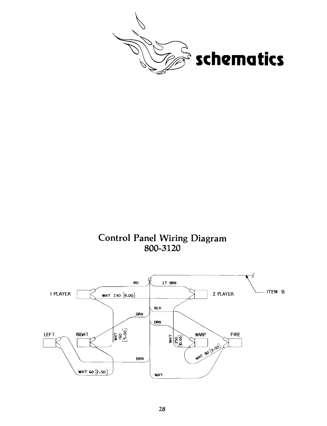
L PARTS LIST assembly control panel
DWG NO. 800-3120 Item Gremlin Qty Per
| # | Part # | Assembly | Description |
1 | 253-0196 1 | GRapHic CONTROL PANEL
| 2 | 250-0367 | 1 | SUB PANEL METAL S/F UP |
| 3 | 253-0031 | 12 | SPACER, WICO SWITCH |
| 4 | 510-0023 | 6 | ASSEMBLY SWITCH WICO |
| 5 | 240-0111 | 1 | BUTTON PLGR BLUE |
| 6 | 240-0006 | 1 | BUTTON PLGR RED |
| 7 | 240-0009 | 4 | BUTTON PLGR YEL |
| 8 | 800-3130 | 1 | ASSY HARN PLAYER CONTROL |
| 9 | 280-0327 | 2 | BASE TIE WRAP |
| 10 | 280-0005 | 2 | CABLE TIE |
ey 7 me U SECTION AA 2PL
Control Panel 800-3120
assembly linear power supply
PARTS LIST DWG NO. 800-0146
Item Gremlin Qty Per
| # | Part ¢ | Assembly | Description |
| 1 | 211-0005 | 7 | CONN CRIMP LOCK |
| 2 | 211-0017 | 1 | CONN FEM QUICK ™% |
| 3 | 211-0042 | 5 | CONN SOCKET AMP |
| 4 | 211-0059 | 1 | CONN PLUG 3 PIN AMP |
| 5 | 212-0016 | 1 | CONN FEM 10 PIN |
| 6 | 250-0433 | 1 | HEAT SINK PWR SPLY ISOL |
| 7 | 250-0434 | 1 | CHASSIS PWR SPLY ISOL |
| 8 | 280-0005 | 4 | CABLE TIE |
| 9 | 280-0014 | 6 | STAND OFF CLIPS |
| 10 | 280-0117 | 1 | TAB, RIVET |
| 1 | 560-0054 | 1 | XFMR ISOL |
| 12 | 800-0128 | 1 | P.C. ASSY GM PWR SPLY |
| 13 | 4 | RIVET POP 3/16 | |
| 14 | 8 | SCR MACH PN HD #4-40x % | |
| 15 | 6 | SCR SHT METAL #6 X % | |
| 16 | 4 | WASHER FLAT #10 | |
| 17 | 6 | TRANSISTOR INSULATOR | |
| 18 | 211-0043 | 1 | CONN PLUG 2 PIN AMP |
| 19 | 280-0323 | 2 | ELECTRIC TAP SPLICE |
| 20 | 600-0079 | 6” | 2 COND ZIP CORD |
- oo QPL a Oo a= sa © teal taal Tas Gad Tad ©
oO
3PL ©) 2 ITEM &
2)
nace wee)
DETAIL A : ; 2 S+-7 —S A LJ L__-F>
Assembly Linear Power zi
Supply = 800-0146 @) 6PL
Assembly Linear Power Supply
800-0146
© /
a / |
| / (oo \
| ' | / | - |
| o] | BRN | __/ |
| : | EC a | on |
| va | | BRN | i} |
7 a7 Wt
| “| | wx wooo fae) | of | (ow |
D z RED G s| RD / VEL 7A eal [een ' ijl} Le 226.00 [2.00]
i je 118.00 [2.00] - +]
\ ~\Ssrecommended spare parts
Quantities
| Gremlin Part # | Description | Per 10 Games | |
| 130-0001 | Speaker | 1 | |
| 130-0002 | speaker cover | 2 | |
| 200-0019, 21/22 | color monitor | 1 | |
| 220-0035 | lock (coin door) | 2 | |
| 220-0066 | coin mechanism | 2 | |
| 240-0006 | red button | 5 | |
| 240-0009 | yellow button | 5 | |
| 240-0111 | blue button | 5 | |
| 250-0034 | spring retainer | 5 | |
| 250-0285 | front cash door | 1 | |
| 253-0104 | panel monitor | 1 | |
| 253-0197 | | | panel logo S/F | 2 |
| 253-0196 | | | control panel graphics S/F | 1 |
| 390-0019 | fluorescent lamp | 1 | |
| 420-0532 | | | interior graphics S/F | 1 |
| 420-0533 | manual S/F | 2 | |
| 420-0486 | manual electrohome monitor | 1 | |
| 510-0051 | switch pushbutton slide | 1 | |
| 510-0023 | WICO switch assembly | 5 | |
| 514-0001 | 2A fuse (AC junction box) | | | 5 |
| 560-0054 | game transformer | 1 | |
| 230-0013 | 8.00 MHZ crystal | 3 | |
| 834-0041 | video interface board | 1 | |
| 514-0002 | 3A fuse (power supply board) | 5 | |
| 514-0006 | 1.5A fuse (power supply board) | 5 | |
| 230-0032 | 20.160 MHZ crystal | 3 | |
| 316-0767 | TST 5E Eprom (CPU) | 1 | |
| 316-0768 | TST 5F Eprom (CPU) | 1 | |
| 316-0769 | TST 5H Eprom (CPU) | 1 | |
| 316-0770 | TST 5I Eprom (CPU) | 1 | |
| 316-0771 | TST 5J Eprom (CPU) | 1 | |
| 316-0772 | TST 5K Eprom (CPU) | 1 | |
| 316-0773 | TST 5M Eprom (CPU) | 1 | |
| 316-0774 | TST 5N Eprom (CPU) | 1 | |
| 316-0775 | TST 20 Eprom (sound) | 1 | |
| 316-0776 | TST 5K Eprom (video) | 1 | |
| 316-0777 | TST 6K Eprom (video) | 1 | |
| 313-0036 | MB3712 IC (linear-sound) | 3 | |
| 315-0069 | 8020 IC (ram-video) | 3 | |
| 315-0071 | MB7063 IC (ram-video) | 3 | |
| 316-0778 | 41-A Prom (video) | 2 | |
| 316-0779 | 3N-A Prom video) | 2 |
This page is a drawing, shown as the original scan.
BLOCK DIAGRAM: Refer to schematics for parts that make up this diagram.
Logic Board 4A. Logic Board 1A, 1G, and 2A.
- Logic Board 8.00 MHZ Crystal, 20.160 MHZ Crystal.
- Logic Board AO through A15 on Z80, buffered by 5B, 5C, and 5D.
- D0 through D7 on Z80, buffered by 4B and 4C.
- Logic Board 4E, 4F, 4G, and 4H.
- Logic Board All Eproms.
- Logic Board 31, 41 and 4J; Video Board 4B, 5A, and 6A.
- Video Board 5B, 5C, 5D, 5E, 6B, 6C, 6D, 6E, 6G and 6H.
- Video Board 4B and 5A; Logic Board 3A, 3B, 4A, 4L, and 6A.
- Logic Board 3A, 3B, 31, 4A, and 4L.
- Logic Board 1J, 1K, and 1L. 13 Logic Board 1G, 2B, 2C, 2D, 2J, 2L, 2N, 3G, and 3J.
- Logic Board 1A, 1B, 1C, 1D, 1E, 1F, 1G, 2B, 2C, 2D, 2E, 2F, 21, 2J, 2K, 2L, 2M, and 2N.
- Video Board 5K and 6K.
- Video Board 3H, 4H, 4N, 5M, and 6M.
- Video Board 1A and 3N.
- Monitor.
- Player controls. Ne 14 VIDEO TIMING
input strobe output strobe
- __ | LOGIC
3 _| CLOCK CPU memory CRT beam el &
Tr address position addr. blanking
ddress b aceress bus _4 JADDRESS MULTIPLEXER) 8
1 READ- | 6 | READ- | 7 _ | REFRESH SHIFT |_|_~} VIDEO | ,, WRITE ONLY MEMORY| 10 16 |REGISTER COMBINER
MEMORY MEMORY ICONTROL, 7
CPU Vv Z80A VIDEO REFRESH 9 MEMORY | (READ-WRITE) CHARACTER
| data bus | C | | | GENERATOR |
| (8 lines) | <7 | MEMORY | 15 |
(READ-ONLY)
| TIMING & |? | Npur | 2? fourpur| 73 crt ie
| CONTROL | PORTS | PORTS |
LOGIC ready =.
player controls
| mem R | 19 | +V | sound indicators |
mem W
This page reads as a drawing: its text was drawn rather than typeset, and comes out in fragments. See the original scan.
This page reads as a drawing: its text was drawn rather than typeset, and comes out in fragments. See the original scan.
| P3 | P3 | REVISIONS | ||
| (roms a3 AU) | rensvdsrpessaire | eRe [a | BESERIPTON | one | arenoven |
oo A] RELEASED JR -3-00| ©
| ALBA] 23 | : | 30] Gb |
25 |conT G. WB) 4 33 |Ga
| Gna} er | ice | § —__________les |a, | ||||||
| nowy. | 741800 | 24 |conT B. | D | |||||
| veck} 5 | Ic4 | a | LP | S—!0 | ||||
| satel | cK ot | 6 | a8 | S | ||||
| = | Tz) | 7 | 7741305 | MLSKA | istrad’? | C4) py = 12) | Poo8___ia4 |ra | ||
| vey '° | 7aT$00 | © | deaoo | |e sh | +2 | . | Boi} | tise | 26 \aLrp |
| SOL | 9 | cy | zeadnev & RIE | 31 | Rb | ||||
| 9 | cs. 3 208, | l3e JCONT R. | ||||||
| DOT CK) G-L-——2Rp>&§ + $324 | i | 7 | c44 | P] | ||||
| riisos | 2 | Ree | Eby | (136-04-30- 1/4) | |||||
| "or | y | te | 3] SP | |||||
| an | ZEOAATIOV | 3/38 | ||||||
| ve} 3a | ibe | : | ‘ | = 620 | a | |||
| LJ | qWrsos | 7A | Re | Toe | Mare | |||
| Q | me | nao | at eN | |||||
| | | 140K | Sak |
reo [ees 71 Be pxcoB le
- BS 5 1O3af Out | 2 8 pe ley c Bl _Vpee Mc jour (-) Thana Rb3 b2K Ch Z [*
| i | @ | aaa |
| (3616-30-19) | Aarnsos am | 3B |
5 __
| 4 | re | aisos | |
| 4 LM324 | (C46) | f | i | |
| e | 741805, be | Pw | |
| I | 4 | +) (C18. | Ale 1 |
it TRID ATS3
B
| 6 | T4LS05 | R | ||||
| eyo | RB at RAL | | | Mm | fi | ||
| 7 | 1 | ‘% | Te | E | ql | = |
6 <
| 10] | LSio+ | T4864 | DIO | = |
| NOTES: | 2 | Bo] ST ete. | Se eESeRTON |
- -@ t5V. PARTS LIST
| 2. ©: BYPASS CAP .0683 uf. | iuenscns ape in inewes” = [ONT NS | Gremlin industries, Inc. |
: San Diese, eatiornia
| 3. ©= |.C. SOCKET TO BE USED. | i | —— | oan | A | |
| 4, =SELECTABLE PARTS NOT | re | loam Tay REEVES 17-16-60) | Programable | ||
| MOUNTED BY TST. | FR AAD | bolas | S | dB | d |
| 5, G)=CUT LAND ON ROB. | TE Lskownk |o2-g0 | oun | Oar |
é. C45 MUST BE LOCATED AT TEE DE TOERT WO BRAWN FS REV MOST END OF ANALOG CIRCUIT. 7 ext ASSY USED ON [APPLICATION ‘DO_NOT_SCALE_ORAWING
REVISIONS [ [apRecease> do a-0o] ag
RED BLUE WHITE BLUE WHITE SYNC B G R
YELLOW
pp [834-0001 |" cae NONE [deer or
| 4 | 3 | 2 | 1 |
REVISIONS
| zone [a | DescAIPTON | one | neenoveo |
A | RELEASED ereJiva_| 7-23 4
| wr | + | 86> +5 |
| M501 (4) | oa | & |
2 c26
| z80vac OF | 126 svc | R? | ie | = 100 UF |
| 12, | TO | 25vV | ||
| usvac OF | 100 VAC F won ror} > ¥ | es | ||
| toovac O2 | NWS ovac | 7 | ||
| ovac oO! | ve | + |
RB cl l RI BS | .05ur 4.7K
a
+—<5> ond G
7-5
+Vce
i i
| > +12 | ov | i |
| +12 | w | as L--=-—— L-4 |
ix 2N4401 cr RI7
| Rat | | apV dt cee | *150UF | per | on | |
| 2.7K | bi | JT 4700 uF | T 25v | RI8 | cl2 |
| 2sv | ov | 220 | -—+ |
AUDIO IN rr sa +001 UF 4, 1UH
- rogas'
| -2 | lov | R26 |
| ) | oe | 10 |
INS231 R28
| R28 | 1O0PF | x | ||
| +Lo3, | [20 | c19 | g | |
| v | IOUF | >.05UF | Jou | 3 |
| + C23 | qv T | i 7 | \ | |
| 7 4700 UF | Ow fase | 3 | ||
| 25Vv | ;o7 | o |
=20V us ~i2v \ +A ; ay 3207-12 | St AUDIO AMPLIFIER, Vee -23v R13 0.2 3W 4 +
| I £9. [ae | P| | NOMERSTURE | |
| % a.c | 160 UF | eo] BE | otne no | SR SERN |
$ 25V PARTS UST
| PENS aae Woes | [ONT NO | Gremlin Industries, Inc. |
FRACTIONS DECIMALS ANGLES San Stowe, cetitorots 2%
| = | as | 2 | APRA | OnE |
| Be | aa | aa |
RTE
Game Power Supply
|, ALL RESISTANCE VALUES ARE IN OHMS, |/2W, 257. NOTES! UNLESS OTHERWISE INDICATED SE] ODE TET WORE HO a B00-A)l4ie =|
| De | ear | D | 800-0128 | 4 |
| APPLICATION | DO NOT SCALE_ORAWING | Scale NOWE | sneer |
7 1
This page reads as a drawing: its text was drawn rather than typeset, and comes out in fragments. See the original scan.
This page reads as a drawing: its text was drawn rather than typeset, and comes out in fragments. See the original scan.
FUSE # 250 -0430
SPLICE
POWER SUPPLY
WARN # 800-3126
a 250-0430 TST VIDEO
TST-ESS SOUND BOARD SIS? SS S4 $5 So S7 SB -5 +545 -H2-+412 END END PZ | 3 2 1 REINS woe SonrON one [aera A | RELEASED SO [io-2-80[n. ARON
TL wm 2 50-05 au omn 5 A D
8.0. SPEAKER
CONTROL PANEL
Cc
ia 5 S| HARN . # 800 - 3127 z i +
TST- CPU CPU B
<=
$ Ay saRN 200-3124 8 : &
PARTS LST | he po Gremlin Industries, Ine. FRACTIONS DECIMALS = m= ANGLES APPROVALS
NEXT ASST USED ON Ti biske wink, Top Assembly Upright SE [OODE TENT NO, D [DRAWING NO- | ev. 700-0040 |
[APPLICATION DO NOT SCALE DRAWING [SCALE NONE sneer 7_of 7
WE WELCOME YOUR COMMENTS!
Your comments and suggestions will assist us in improving the usefulness of our publications. They are an integral part of preparing for revisions of manuals and parts catalogs.
If you have any technical questions about any Gremlin/Sega game, are requesting additional publications, or have a suggestion about how we can make our publications more useful to you, drop us a line or use the handy form below. We value your input.
Comments:
Fill in if you wish a reply:
Name Firm 0) Distributor
Address Operator City State Zip C) Other
BUSINESS REPLY MAIL No Postage Stamp Necessary If Mailed Within United States
Postage Paid By
Gremlin/SEGA 8401 Aero Drive San Diego, CA. 92123
Attn: Customer Service
Second Fold
apg sty ade First Class 10125 E Zz A
This page carries no recoverable text. It is a drawing or a photograph. See the original scan.