CarnEvil 2-Player Dedicated 25in (16-40069-101 Nov 1998)
CarnEvil (v1.0.3) (Midway Games, 1998) · Manual · 88 pages · 65 sections · original scan
MID WA Y NOVEMBER 1998
16-40069-101
2-PLAYER
DEDICATED 25” VIDEO GAME
ce ©. LISTED
Operation Manual, Including... @ Installation & Operation @ Testing & Problem Diagnosis @ Parts Information © Wiring Diagrams
Midway Games Inc. 3401 North California Avenue Chicago, Illinois 60618-5899 USA
This page carries no recoverable text. It is a drawing or a photograph. See the original scan.
DECLARATION OF CONFORMITY
MIDWAY GAMES INC
3401 N. CALIFORNIA AVE. CHICAGO, IL 60618 US.A.
WE, HEREBY DECLARE UNDER SOLE RESPONSIBILITY THAT
THE MODEL: "carneviL” 25" 40269,40369,40469,40769,40969,41069,41169,41269, 41469,41869,41969,42069,42169,42269,47269
TO WHICH THIS DECLARATION RELATES IS IN CONFORMITY WITH THE FOLLOWING EUROPEAN PRODUCT SAFETY
ELE OMAGNETI! DIRECTIVE (89/336/EEC AND AMENDMENTS 91/C162/08, 92/31/EEC,93/68/EEC
CAL D FOR
CERTAIN VOLTAGE LIMITS DIRECTIVE
(73/336/EEC AND AMENDMENTS 88/C168/02, 92/C210/01, 93/68/EEC,94/C199/03, 95/C214/02)
AS IS VERIFIED BY COMPLIANCE WITH THE FOLLOWING
EN55014: 1993 EN61000-4-2: 1995 IEC 801-3: 1984 (EN61000-4-3) EN61000-4-4: 1995 EN61000-4-5: 1995 EN335-1: 1995 IEC 335-2-82 (DRAFT)
Date issued: OCTOBER 21,1998
DAN GALARDE
CORPORATE V.P. OF QUALITY
This page carries no recoverable text. It is a drawing or a photograph. See the original scan.
CARNEVIL..
SECTION
ONE
INSTALLATION, OPERATION
& SERVICING
NOTICE: Information in this manual is subject to change without notice. MIDWAY reserves the tight to make improvements in equipment function, design, or components as progress in engineering or manufacturing methods may warrant.
Fill out and mail in the Game Information Card. Be sure to include the game serial number from the label on the rear of the cabinet. For your records, write the game serial number in the manual. SERIAL NUMBER
SAFETY INSTRUCTIONS
The following safety instructions apply to operators and service personnel. Read these instructions before preparing your game for play. Other safety instructions appear throughout this manual.
DEFINITIONS OF SAFETY TERMS
NOTICE indicates information of special importance.
> fh @ @Bre
EPILEPSY WARNING A very small portion of the population has a condition which may cause them to experience epileptic seizures or have momentary loss of consciousness when viewing certain kinds of flashing lights or patterns that are present in our daily environment. These persons may experience seizures while watching some kinds of television pictures or playing certain video games. People who have not had any previous seizures may nonetheless have an undetected epileptic condition.
If you or anyone in your family has experienced symptoms linked to an epileptic condition (eg., seizures or loss of awareness), immediately consult your physician before using any video games.
We recommend that parents observe their children while they play video games. If you or your child experience the following symptoms: dizziness, altered vision, eye or muscle twitching, involuntary movements, loss of awareness, disorientation, or convulsions, DISCONTINUE USE IMMEDIATELY and consult your physician.
PRODUCT SPECIFICATIONS
Operating Requirements
Location Electrical Power Temperature Humidity
| Domestic | 120VAC @ 60Hz3.0 Amps | 32°F to 100°F | Not to exceed 95% relative |
Foreign 230VAC @ 50Hz2.0 Amps (0°C to 38°C) Japan 100VAC @ 50Hz 3.0 Amps
Cabinet Statistics
| Shipping Dimensions | Shipping Weight | Design Type | ||
| Width | 29.5" (75 cm) | 340 Lbs. | (154.5 kg.) | Dedicated Video Game |
Depth 38.0" (96.5 cm) with Optical Shotguns Height 72.5” (184.2 cm)
Equipment Characteristics
| Video Display Monitor | Audio System | Currenc) | tors |
| Standard Resolution RGB | Digital Stereo Sound | 2 Coin Mechanism, Coin Counter | |
| 25” (63.5 cm) CRT | with 6x9” (15x23 cm) | Dollar Bill Validator Ready |
Full Range Speakers Electronic Coin Acceptor Ready
Game Characteristics
| Player Variables | Operator Variables | Diagnostics |
| 1 or 2 players per game | Coinage, Game Options | Automatic Power-Up Self-Test |
| High Score Recognition | Difficulty, Volume, | Manual Multi-Level Menu System |
Audits, Statistics ——— a INSTALLATION & INSPECTION
- Remove all items from the shipping containers and set them aside. Inspect the exterior of the cabinet, control panel, and guns for any damage. Pay special attention to cabinet edges, seams, and corners.
- Remove and save the screws at the top and sides of the rear door. Unlock the rear door, then lift it off of the cabinet and set it aside. Inspect the cabinet interior for any signs of damage. Check all major assemblies to assure that they are mounted securely. Check the shotguns for signs of damage.
- The coin door keys are attached to a trigger on one of the guns. Unlock and open the coin door. The cash box door and rear door keys are located on a key hook attached to the rear of the coin door. Unlock and open the cash box door. Remove the spare parts stored in the cash box.
- Leg levelers and nuts are located in the spare parts. Install one nut onto each leg leveler and hand turn it up against the base of the leg leveler. Install one leveler with its nut into the threaded hole in each corner of the cabinet. Turn them all the way into the holes, but do not tighten at this time.
- Refer to the Cabinet Wiring Diagram (Section 4), and check to see that all cable connectors are correctly secured. Do not force connectors; they are keyed to fit in only one location. Bent pins and reversed connections may damage your game and void the warranty.
- Locate the gun holster assemblies. There are three mounting holes in a triangular pattern on either side of the coin door. Orient the holsters over the holes and install with tamper resistant screws.
1-4
- An extra padlock may be installed to secure the rear door. A hasp is located in the Spare parts bag. Remove the two lock bracket nuts from inside the cabinet, above the rear door opening. Slide the hasp onto the bolts so that it protrudes from the hole in back of the cabinet. Reinstall nuts and tighten.
- Modify the lock plate at the top of the rear door. Remove the bolts and nuts from the lock plate, then rotate the plate so that the slot will be above the door. Reinstall the bolts and nuts and tighten firmly.
CARRIAGE BOLT
HASP BRACKET
KEY LOCK Lock BRACKET PLATE
CARRIAGE, CABINET SHOWN FOR REFERENCE BOLT
- The power cord is with the spare parts. Remove and save four screws from the line cord cover plate at the rear of the cabinet. Match the holes on the IEC plug with the prongs in the receptacle and push firmly to seat the line cord. Route the cord away from cabinet wheels and foot traffic areas. Hang excess cord on the plastic clip near the vent.
(PART OF CABINET SHOWN FOR REFERENCE ONLY) RECEPTACLE:
PHILLIPS—HEAD
LINE CORD AND PLUG
LINE CORD INSTALLATION
- Reinstall the rear door onto the cabinet and close it. Lock the rear door and remove the key. If required, install the extra padlock through the hasp at this time. Install the screws at the top and sides of the rear door and tighten snugly. Close and lock the cash box and coin doors.
NOTICE: Tamper resistant screws and matching wrench are provided with this game for additional security. Four tamper resistant screws and one wrench are located in the spare parts bag. If desired, replace the original screws with the tamper resistant screws. Tighten the screws firmly with the wrench.
- Move the game to its intended location. Lower each leg leveler until the cabinet is stable and level. Adjust as required to raise wheels and distribute weight equally on each corner. Tighten the nuts.
- Plug the game into a grounded (3-terminal) AC wall outlet. Switch ON the game, using the ON/OFF ‘switch at the top left rear of the cabinet. The game will power up and begin self-diagnostics. If no errors are found, the game will automatically enter its “attract” mode of operation. Unlock and open the coin door. Locate the control switches. Press TEST MODE to enter the Menu System.
- Perform a gun test on each shotgun. Access to this test is from the Diagnostic screen of game’s Menu System. See Section Three for a detailed description of the Menu System. The gun test verifies that the shotguns function properly to allow normal game play.
- If necessary, calibrate the shotguns. Access to the calibration feature is from the Utilities screen of game’s Menu System. See Section Three. Calibration restores shotgun accuracy to original factory level of performance. Since player satisfaction depends on gun performance, you should recalibrate and test shotguns periodically.
1-6
CABINET ASSEMBLY
MONITOR CONTROLS
COIN METER —J
FRONT VIEW OF CABINET
1-7
MAINTENANCE
@ Viewing Glass It is not necessary to switch off power to the game to clean the glass. Apply a mild glass cleaner to a clean cloth or sponge. Use this to wipe the viewing glass. Do not apply the cleaner directly on the glass! Liquid could drip down into switch or motor circuits and cause erratic game operation.
@ Cabinet Use only non-abrasive cleaners to avoid damaging game graphics. Apply cleaner to a clean cloth or sponge. Use this to wipe the screen clean. Do not apply the cleaner directly on the cabinet!
@ Shotguns Dirt or debris on a shotgun lens can affect accuracy. Apply the cleaner to a clean cloth or cotton swab, and then use this to wipe the lens clean. Do not apply cleaner directly into the gun barrel!
SERVICING Only qualified service personnel should perform maintenance and repairs. The following product guidelines apply to all game operators and service personnel. Notes, cautions and warnings appear throughout this manual where they apply. Read the SAFETY pages thoroughly before beginning service.
@ Shotguns Switch off power to the game. Unlock and open the coin door. Disconnect the shotgun cable from the wiring hamess. Remove the locking nuts. Lift the gun cable mount off the front of the cabinet. Retain carriage bolts and nuts from the mount for reinstallation. Reattach the ground connection. Check that the gun cable rotates freely in its mount. Reinstall the carriage bolts. Tighten the locking nuts.
To disassemble a shotgun, lay the gun on a work surface and remove the screws. Separate the gun halves, beginning at the handle. Take care not to dislodge parts (the trigger is spring loaded.) Clean the lens to remove fingerprints and dust. If you removed any shields from the gun, reinstall them. After re-installation, verify that a good electrical connection exists between the shield and cable ground. Test the pump action to insure it does not bind. Always recalibrate a shotgun after servicing.
@ Coin Mechanism Switch off power to the game. Unlock the coin door and swing it open. To clean a coin mechanism or replace it with a different type, unlatch and remove it. After reinstallation, ensure that the mechanism seats fully in the holder. Close and lock the release latch, and then close the door. Turn on the game and change the mechanism setup. Test known good and bad coins to verify operation.
@ Dollar Bill Validator (Use MARS AE2411-U5 U.L. Recognized currency changer) Dollar bill validators or other currency acceptors may be installed in games that were manufactured with the additional wiring connector factory installed. Switch off power to the game and unplug the AC. line cord. Unlock the coin door and swing it open. Read the door label for additional information. Remove nuts, spacers, and the cover plate from the door. Change switch settings and make other adjustments before mounting the unit. If the manufacturer has supplied an adapter plate, place it over the door cutout. Install spacers on threaded studs. Align validator mounting holes with the studs. Seat the unit in the door opening. Install the nuts and tighten them firmly. Attach the ground wire (green with a yellow stripe) lug to the door ground stud next to the hinge. Mate the wiring harnesses. Press down on connectors to fully seat them. Route wires away from the door edges and hinge. Check for proper bill chute alignment. Plug in the line cord and turn on the game. Change the mechanism setup and pricing as required. Test known good and bad bills to verify proper operation. After you are satisfied with validator operation, close and lock the coin door.
Bill Acceptor Specifications
Pulse Width | 50 mS minimum on; 50 mS minimum off Pulses 1 pulse per dollar
VOL 0.4V @ 5mA
VOH 3.5V @ -0.4mA
@ Coin Meter Switch off power to the game. Unlock the cash door and swing it open. The meter is at the lower left corner of the door opening. Record the meter count before testing or replacement.
Insert a finger through the access hole under the cash tub. Locate the meter wires. Disconnect the hamess at the connectors. Remove front screws and slide the meter out. Ensure that the replacement unit has a protective diode connected across the terminals to prevent driver circuit damage.
1-9
CABINET FRONT VIEW
MARQUEE —
BEZEL —
VIEWING GLASS—
2— START
BUTTONS
U
COIN DOOR— SPEAKERS
CASH DOOR
LEG LEVELERS
EXTERNAL COMPONENTS
1-10 / Q
a ¢ Viewing Glass : Remove the screws from the top of the cabinet directly over the marquee. Lift the retaining strip of of the cabinet. Tilt the glass slightly forward, grasp it firmly by its edges, and lift it out of the cabinet. The marquee artwork may be removed if required. Clean and inspect the lamp before reassembling.
¢ Fluorescent Lamp Remove the screws from the rear lamp access panel. Unlock it and lift from the cabinet. Reach over the top of the assembly and grasp the tube. Give it a quarter turn and pull it out from its sockets. The electronic ballast in this assembly does not require a separate starter. Carefully place a new tube into the socket and rotate it a quarter turn to reinstall. Clean the tube to remove fingerprints and dust.
¢@ Fluorescent Light Assembly Remove the screws from the rear lamp access panel. Unlock it and lift from the cabinet. Disconnect the power cable from the fluorescent light assembly. Loosen but do not remove the fasteners holding the assembly to the cabinet. If present, remove the ground wire. Slide the assembly slightly forward to disengage the screws from the keyholes. Lift the assembly and guide it out of the cabinet.
¢ Speakers The grilles and the speakers come out from the front. Remove the screws and set the grilles aside. To avoid damaging a speaker, remove upper mounting screws first, and replace them last. Remove the speakers from the enclosure just enough to expose the terminals. Label and disconnect the co wires. Refer to the Wiring Diagram (Section Four) for speaker wiring information. Tighten screws snugly. Do not use excess force when removing or tightening screws threaded into plastic or particle board.
¢ Control Panel Switches Remove grilles and speakers. Label and disconnect wires. Separate the switch from its button housing. Bend the large prong away from the switch just enough to slide the switch off the housing. Unscrew the switch mounting nut and pull the entire button assembly out the front of the control panel.
« Power Supply Switch off power to the game. Unlock and remove the rear door. Unplug the IEC A.C. connector from the rear and the D.C. connector from the front of the assembly. Remove two top and two bottom screws holding the supply to the power chassis, then lift it off the power chassis. Note voltage setting.
To install a power supply, remove the voltage switch cover if necessary and set the voltage to the correct value. Set the supply on the power chassis and align the mounting holes. Install the four screws and the two power connectors.
CABINET REAR VIEW
OPTICAL GUN ASSEMBLY
POWER SUPPLY ASSEMBLY
LINE CORD
FIXED CASTER WHEEL REAR DOOR ASSEMBLY —~
INTERNAL COMPONENTS
1-12 LAMP ACCESS PANEL
LOUVERED VENT
HANDLE
PLASTIC CLIP
—— MONITOR
ELECTRONICS -— ASSEMBLY
CAM LOCK ASSEMBLY
LOCK PLATE
an @ Monitor Bezel Remove the viewing glass. Grasp the monitor bezel at the bottom and lift it out of the groove.
. @ Monitor Read these precautions thoroughly before beginning this procedure.
Switch off power to the game. Unlock and remove the rear door. Disconnect the monitor from the wiring harness, remote adjustment board, and ground wires. Remove the retaining strip and the viewing glass. Remove the monitor bezel and both barrier panels. Remove the fasteners holding the monitor frame to the upper and lower mounting brackets. Pull the monitor carefully from the cabinet and set it in a safe place. Remove the remote adjustment board from the cabinet and reconnect it to the monitor before servicing or replacement. Clean the monitor face and the bezel before reinstalling.
@ CPU Fan Assembly Switch off power to the game. Unlock and open the rear door. To expose the CPU Board Assembly, fc remove the perforated metal cover from the game electronics. Disconnect the fan connector from the wiring harness. Remove fasteners and lift the fan assembly out of cabinet. Separate the mounting bracket from fan. Retain the bracket and the connector for reuse if a different fan must be installed.
@ CPU Board Assembly Switch off power to the game. Open the rear door. To expose the CPU Board Assembly, remove its perforated metal cover. Carefully note the orientation of the JAMMA connector and the other cables. Extract the harness and the hard disk drive ribbon cable from the board connectors. Remove CPU Board Assembly mounting screws. Lift the board out of the cabinet and set it in a safe place. Use anti-static bags or protective containers from new parts to store boards that you don’t plan to reinstall.
Gun Interface Board Assembly Switch off power to the game. Unlock and remove the rear cabinet door. To expose the Gun Interface Board Assembly, remove the perforated metal cover. Disconnect the wiring harness and the fuses from the interface board assembly. Remove two large and two small screws holding the board assembly in place and retain them along with their washers. Lift the board out of the cabinet and set it in a safe place. Set the replacement board assembly over the CPU board, align the holes and install the screws, small ones first. Reinstall the fuses and reconnect the wiring harness to this board.
GAME ELECTRONICS
MEMORY CIRCUITS
GUN INTERFACE ———ll, BOARD ASSEMBLY
WOOD PANEL——— |
CPU BOARD—~ ASSEMBLY
STEEL PLATE——~
ELECTRONICS FERRITE BEADS
HARNESS.
DIP SWITCHES
| ——~—HaRD DISK DRIVE/ FAN POWER CABLE
/ FAN ASSEMBLY
HARD DRIVE RIBBON CABLE
HARD DISK DRIVE ASSEMBLY
GROMMETS
___DIP SWITCH ACCESS SLOT
PERFORATED METAL COVER
DN | GROMMETS
INTERNAL COMPONENTS
1-14
@ Hard Disk Drive Use an anti-static bag and approved shipping container (P/N 08-8068) to return the hard disk drive assembly to your distributor. Switch off power to the game. Unlock and remove the rear cabinet door. Remove the perforated metal cover over the game electronics. Disconnect the D.C. power cable from the hard disk drive. Unplug the ribbon cable from the hard drive and leave it attached to the CPU Board. Carefully loosen the screws and lift the drive assembly out of its mounting bracket. Remove the screws and reuse them if a different hard disk drive assembly is to be installed.
NOTICE: Hard disk drives are very fragile! Handle them with care. Do not stack or drop hard disk drives. Keep the disk drives away from magnets, heat and vibration.
@ Memory The ROM (Read Only Memory) circuits contain the computer operating instructions for this game. Switch off power to the game. Unlock and remove the rear door. Remove the perforated metal cover. Carefully note the Integrated Circuit position, then remove the device with a chip extraction tool. To reinstall memory circuits, orient the device over its socket and press firmly to seat pins. Do not force.
@ Battery Switch off power to the game. Unlock and remove the rear door. Remove the perforated metal cover. Carefully note the battery position, then gently lift the contact arm to release tension. Do not bend the arm with excess force. Slight finger pressure may be needed to pry the cell from its holder. Slide the battery out and remove from the cabinet. Avoid direct shorts across terminals or terminals to ground.
GAME OPERATION
STARTING UP Whenever you turn on the machine or restore power, the system executes boot ROM code. The boot ROM contains self-diagnostic tests. These tests automatically verify and report the condition of the disk drive and other hardware. The screen is blank during these tests. If the hardware fails a test, the system displays an error message. The message appears for 30 seconds or until someone presses a button. ¢ If nobody presses a button, the system quickly completes tests, and then loads game software.
- To skip boot ROM tests and activate the Menu System, press and hold the TEST MODE button.
Having passed power-up tests, the system enters Attract Mode. Attract Mode consists of typical game scenes and sounds, alternating with high scores. Attract Mode continues until game play commences.
Players insert currency to start the game. Then they select a CarnEvil territory. As a player chooses a shotgun, the player also selects a character. The game identifies one character with green shotgun blasts. The game associates the second character with purple shotgun blasts. Each character receives a starting health level. Play begins after a countdown period. The game progresses until players exhaust their characters’ health. If players choose not to continue, then the system returns to Attract Mode.
GAME RULES
ONE OR TWO PLAYERS The player or players insert currency to start the game. Each player chooses a gun and presses the nearest START button. At the CarnEvil ticket booth, either player selects a territory to begin an adventure. Indicator bars at the sides of the screen track remaining ammunition for each player.
PLAYER CONTROLS
¢@ START Buttons These buttons allow players to begin or continue play.
@ SHOTGUNS Use a shotgun to shoot killer clowns and other enemies. Also use a shotgun to shoot player health and gun-upgrade symbols. To reload the gun, pump it or shoot off-screen. SIGHT
PUMP. GUARD
METAL CABLE——~
SHOTGUN PARTS
OPERATOR CONTROLS
CABINET CONTROLS
o The DIP Switches are beneath the monitor, on the main PC board. Access these switches by opening the rear door. DIP switches set some system variables. You can set other variables with control switches.
The Monitor Remote Control Board is beneath the monitor, on the rear cabinet wall. Open the coin door to access controls. Use monitor controls to adjust the video display for optimum viewing.
The POWER Switch is at the rear of the cabinet. If you stand behind the cabinet, you'll find the switch on the top-right side. This switch turns off the game, but does not reset game variables.
CONTROL SWITCHES
o The SERVICE CREDITS Button is behind the coin door, on a rear wall bracket. This button allots credits without changing the game's bookkeeping total.
The TEST MODE Button is behind the coin door, on a rear wall bracket. Actuating TEST MODE causes the game to enter the menu system. Press the TEST MODE button briefly to run automatic tests. To make changes, press and hold TEST MODE until the system menu appears.
VOLUME DOWN and VOLUME UP Buttons are behind the coin door. You'll find them on a rear wall bracket. These buttons set game sound levels. To make minor changes, press either button briefly. To make major changes, press and hold a button.
NOTICE: You must adjust Attract Mode volume independently of Game Mode volume. For greater profits, increase volume levels to draw attention to this game.
NOTICE: To reach control switches, unlock and open the coin door.
NOTICE: The 25-inch CarnEvil machine has no factory-installed tilt switch.
MONITOR ADJUSTMENTS
To_ cr —
- r
CREDITS “Down SERVICE VOLUME VOLUME TEST UP MODE
COIN METER we Be
CONTROL SWITCH LOCATIONS
COIN DOOR
cASHBOX DOOR—~“
COIN METER J
PLAYER CONTROL LOCATIONS
1-18 CONTROL SWITCHES
TO ITEM DETAIL BELOW MENU
MONITOR CONTROLS
CONTROL SWITCHES
lon
GAME FEATURES
CarnEvil is a dark, gloomy, 3-D horror movie, and the player is the ultimate hero. The player must battle up to 40 terrifying villains, each with its own threatening capabilities. Among these are killer clowns, murderous mimes, a savage Santa, marauding maggots and jugular Junior.
Deep within CarnEvil lurk many territories, each with unique, blood-curdling perils and sinister secrets. CamEvil proclaims a sardonic welcome to its every dank domain. Players dare to enter the Haunted House, Rickety Town or the Freak Show. Skill, craft and discipline earn entry into elite domains, such as the bestial Big Top. Here CarnEvil challenges the superior player to a heightened play level.
For the intrepid player, a blazing shotgun is the only way out. The player must remember this essential rhythm: Pump and fire, pump and fire! Then the player moves cautiously forward, flushing out gruesome enemies that never see the daylight.
Threatened by killer clowns, bats, spiders, freaks and others, the player must exterminate them all. If an enemy draws blood, then the player’s health declines. The player achieves extra points by eliminating ravenous villains before they devour the heroine. Yet should a misplaced shot dispatch the lovely heroine, the player pays a penalty.
As play commences, the gun fires single shots, like a pistol. Shooting bullet-shaped symbols upgrades the player's weapon. Upgrades allow the gun to temporarily become a full-fledged shotgun or a machine gun. In all gun modes, the player must periodically pump the gun to reload it. Another way to reload the gun is to aim off screen and press the trigger. The player improves his health by shooting heart-shaped symbols. Then, restored and fortified, the player dares to plunge forth into the next, nightmarish territory.
The screen displays and constantly updates player scores. As players exit a territory, the screen indicates shooting accuracy percentages for each player. As each play level concludes, top scorers may enter initials or names with a shotgun. CarnEvil displays these initials in a high score table.
NOTES
1-20
CARNEVIL..
SECTION
TWO
DIAGNOSTIC, AUDIT & ADJUSTMENT MENU SYSTEM
NOTICE: Information in this manual is subject to change without notice. MIDWAY reserves the right to make improvements in equipment function, design, or components as progress in engineering or manufacturing methods may warrant.
2-1
MENU SYSTEM AUTOMATIC TESTS Whenever you switch the game between Play Mode and the menu system, the self-test routine activates. This routine, which isn’t part of the menu system, runs automatically. Its purpose is to detect faults that prevent the game or menu system from operating properly. Messages appear on the screen as each item runs. These messages may describe detected errors. A self-test usually takes less than one minute to complete. Write down messages before proceeding to the menus or game play.
OPERATOR-SELECTED TESTS The game’s menu system includes a number of operator-selected, manual tests. In this system, a series of on-screen menus presents game variables and diagnostics. The Main Menu screen allows you to view information, make changes, or verify equipment operation. Each submenu screen displays one group of choices. A Detail Menu presents data or runs the required test. You must be at the Detail Menu level to detect errors, make changes, or activate tests.
SCREEN LAYOUT Menu screens differ, but presented material remains in the same location each time. @ The color bar at the top center of each screen displays the current menu title. @ Data (menu items, video signals, statistics, reports, etc.) appears in the center of the screen. @ Messages (explanations, control functions, revision levels) display at the bottom of the screen.
MENU SYSTEM ORGANIZATION You must activate the menu system manually. To play the game, you must also manually exit from the menu. Main Menu items appear in categories: Tests, statistics, audits, adjustments, etc. @ Tests verify proper equipment operation.
Statistics and audits allow you to assess and customize game performance. @ Adjustments help you to customize game performance. For instance, you can restore factory default game settings. You can also calibrate player controls for accuracy.
Submenu screen items offer you choices within a category. Some items have no submenu, while others may have more than one. You can return to the previous menu or go on to the next menu.
Detail Menu screen items contain specific information. You must interact with the system to achieve results or make changes. You can always return to previous menus from Detail Menu screen items.
Control functions appear on a menu screen. Use VOLUME UP and VOLUME DOWN buttons to highlight an item on any menu. (These buttons are inside the coin door.) You can only select one highlighted item at a time. To select a highlighted item, press the TEST MODE (rightmost) pushbutton inside the coin door. To return the game to play, highlight “EXIT,” then press TEST MODE.
CarnEvit MAIN MENU
AUDITS RECALIBRATE GUNS ADJUSTMENTS DIAGNOSTICS VOLUME LEVEL UTILITIES
EXIT
MAIN TEST MENU
2-2
AUDITS Select “AUDITS” at the CarnEvil Main Menu. The Audits menus permit you to review game play statistics. Additional menus give detailed reports for each player position on game starts, ends, cabinet abuse, fault conditions, etc.
Highlight a line item with the middle two control buttons inside the coin door. Select the option with the right control button. The screen displays a list of the statistics available to you. Select an item to view the detailed report.
AUDITS
COIN AUDITS
CREDITS AUDITS
GAME AUDITS
HAUNTED HOUSE AUDITS -
FREAK SHOW AUDITS
RICKETY TOWN AUDITS
BIG TOP AUDITS _
WAVE AUDITS
GAME RESETS
CAND PC
REG DUMP
CLEAR AUDITS
EXIT
AUDITS SUBMENU
Data in the Audits menus helps you to keep records of the game's popularity and earning potential. Each entry on the Audits Submenu is the subject for an entire screen of bookkeeping information. Use the highlight bar to select the desired subject.
Examine and record all game audit values before performing game service or repairs.
NOTICE: Be careful when clearing audit information. Once you clear data, you cannot restore it.
COIN AUDITS Select “COIN AUDITS” at the Audits Menu. The Coin Audits menu permits you to assess the currency collection. This report screen presents revenue quantities and other important game statistics.
Highlight a line item with the middle two control buttons inside the coin door. Select the option with the right control button. A menu screen appears as below.
COIN AUDITS - PAGE: 1
LEFT SLOT COINS XXXXXXXX
RIGHT SLOT COINS XXXXXXXK
BILLS XXXXXXXX
CENTER SLOT COINS © XXXXXXXX
EXTRA SLOT COINS XXXXXXXX
GAME STARTS XXXXXXXX
SERVICE CREDITS XXXXXXXX
TOTAL PLAYS XXXXXXXX
TOTAL COINS XXXXXXXX
COIN AUDITS SUBMENU
The Coin Audits submenu reports total quantities of coins, bills or credits collected by each active device. The submenu does not calculate the value of the collected currency.
This screen reports information, but does not permit you to make changes. To reset the coin, bill, and credit counters to zero, use the Clear Audits menu.
We recommend that you examine and record audit information before you make changes. Once you've cleared the counters, you can’t retrieve the previous data from the system.
CREDITS AUDITS Select “CREDITS AUDITS?” at the Audits Menu. The Credits Audits menu permits you to assess the currency collection. This report screen presents revenue quantities and other important game statistics.
Highlight a line item with the middle two control buttons inside the coin door. Select the option with the right control button. A menu screen appears as below.
CREDITS AUDITS - PAGE: 1
CREDITS AVAILABLE YOOKXXXXX
CREDITS AUDITS SUBMENU
2-4
GAME AUDITS Select “GAME AUDITS’ at the Audits Menu. The Game Audits menus permit you to review the game play statistics.
Highlight a line item with the middle two control buttons inside the coin door. Select the option with the right control button.
GAME AUDITS - PAGE: 1
TOTAL UPTIME DBE TOTAL PLAY TIME 1°" CONTINUE GAME STARTS 2° CONTINUE GAME CONTINUES 3°° CONTINUE LEFT PLAYER 4" CONTINUE RIGHT PLAYER 8™ CONTINUE 1 PLAYER 6™ CONTINUE 2 PLAYER 7™ CONTINUE SBLF’S 8™ CONTINUE
TLF’S 9" CONTINUE
INITIALS ENTERED 10™ CONTINUE ZA CRC 11™ CONTINUE ZM CRC 12". CONTINUE PATH CRC 13" CONTINUE CAM CRC 14™ CONTINUE DBS MORE CONTINUE
GAME AUDIT SUBMENU
The Game Audits menus report information but don’t permit you to make changes. Examine and record information at GAME AUDITS before deleting data at CLEAR AUDITS.
LSW, TLF, SBLF, etc. are terms for internal record keeping counters used in this game.
CLEAR AUDITS Select “CLEAR AUDITS” at the Audits Menu. The Clear Audits menu allows you to clear individual memory counters or to reset them all at one time.
Highlight a line item with the middle two control buttons inside the coin door. Select the option with the tight control button. Options may be reset to factory defaults or changed after each viewing.
CLEAR AUDITS
‘CLEAR COIN AUDITS
CLEAR CREDITS AUDITS
CLEAR HAUNTED HOUSE AUDITS
CLEAR FREAKSHOW AUDITS
(CLEAR RICKETY TOWN AUDITS
CLEAR BIG TOP AUDITS
CLEAR WAVE AUDITS
CLEAR GAME RESETS
CLEAR C AND PC
CLEAR REG DUMP
CLEAR ALL
EXIT
CLEAR AUDITS SUBMENU
You can reset any audit screen from the Clear Audits submenu. Choose any item to return the counters to zero.
© Game Resets keeps track of how the game responds to different player maneuvers. ¢ Cand PC is an internal record-keeping list used to monitor game performance. e Clear All simultaneously changes all audit categories to factory default values.
After you select an item, the game gives you the opportunity to escape from this change. For example:
ARE YOU SURE YOU WANT TO CLEAR COIN AUDITS?
LAST CHANCE SUBMENU
Once you've selected and verified a clear function, the values reset and you can’t restore them. We recommend examining and recording all utility values before making changes.
NOTICE: Be careful when clearing audit information. Once you clear data, you can’t restore it.
2-6 WY
RECALIBRATE GUNS Select “RECALIBRATE GUNS” at the CarnEvil Main Menu. Shotgun recalibration restores shotgun accuracy to original software performance. Of course, shotgun performance also depends on the condition of your game hardware. Since player satisfaction depends on gun performance, you should recalibrate and test shotguns periodically.
LEFT GUN (GREEN)
TOP LEFT
POINT GUN AT X AND PULL TRIGGER PRESS EITHER START BUTTON TO CANCEL
GUN CALIBRATION SCREEN 1
The Gun and Monitor Calibration screen opens. Now highlight “Gun Calibration.” Again, select the option with the right contro! button. The Calibrate Guns screen opens. Turn room lights down to reduce glare that may interfere with gun operation. Before calibrating shotguns, examine shotgun barrels for dirt or debris. No amount of calibration and testing can fix a dirty optical system. The same rule applies to blown gun fuses, loose components, defective cables, etc.
TOP LEFT.
CALIBRATE GUNS
LEFT GUN (GREEN)
PRESS EITHER START BUTTON TO CANCEL To return to menu, Press left START
GUN CALIBRATION SCREEN 2
The screen specifies which gun to shoot. To avoid miscalibration, the other gun temporarily becomes inactive. Stand directly behind the shotgun holder and extend the cable to its full length. An “X” appears at ie soprteft Corner of the screen. Aim precisely, so that the gun sight aligns with the "X.” Fire the gun at the "X.”
A second “X” appears at the bottom-right screen corner. Again, fire the gun at the “X.” When you're done, return to the previous menu by pressing the left START button. Maintain maximum earnings by testing and recalibrating guns often.
NOTICE: Bright overhead lights occasionally interfere with optical gun operation. To eliminate this interference, reduce light levels and recalibrate the shotguns.
2-7
ADJUSTMENTS Select “ADJUSTMENTS” at the CarnEvil Main Menu. The Adjustments menus permit you to change game characteristics. Use these screens to optimize game performance and earnings.
Highlight a line item with the middle two control buttons inside the coin door. Select the option with the right control button.
ADJUSTMENTS
PRICING FREE PLAY ATTRACT SOUND ADDITIONAL ADJUSTMENTS. FULL FACTORY RESTORE
EXIT
ADJUSTMENTS SUBMENU
PRICING Select “PRICING” at the Adjustments Menu. The Pricing menus allow you to view current settings or change the cost of games. Custom pricing allows you to select the number of coins or credits required for each game. The game restores factory default values if you exchange the CPU Board or if the backup battery fails.
Highlight a line item with the middle two control buttons inside the coin door. Select the option with the right control button. You may reset options to factory defaults or change an options after viewing it.
We recommend examining and recording all pricing options before making changes.
You may save several custom prices and then choose between them as needed. Instructions for creating new price settings appear on the screen in sequence to guide you through the custom process.
PRICING
SHOW. CURRENT NORTH AMERICA SOUTH AMERICA EUROPE (A-H) EUROPE (I-U) ASIA
AUSTRALIA
CUSTOM PRICING EXIT
PRICING SUBMENU
An additional box appears on screen to explain the available functions as you select each item.
2-8
CURRENT PRICING
CURRENT PRICING USA 1
LEFT SLOT UNITS
RIGHT SLOT UNITS
CENTER SLOT UNITS
EXTRA SLOT UNITS
BILL VALIDATOR UNITS
UNITS PER CREDIT
UNITS PER BONUS
MINIMUM UNITS
CREDITS TO START
CREDITS TO.CONTINUE
MAX CREDITS
COINS PER BILL RRR ER EN
i
CURRENT PRICING SUBMENU
Select “SHOW CURRENT” at the Pricing Menu. The following definitions clarify the adjustments in the Pricing menus...
SCREEN TERM DEFINITION Slot or Bill Units Inserted coins and bills accumulate units. This adjustment specifies the quantity of units given for each coin or bill in each position (“unit” is an arbitrary term). Units per Credit This number establishes the value of each credit for pricing calculations. Units per Bonus Units awarded after a player has accumulated enough points for a bonus. Minimum Units No credits will be awarded until this many coin or bill units have accumulated.
Credits to Start Credits needed to begin game play. This sets the basic cost per game. Credits to Credits required to continue a game which is already in progress. Continue
Maximum Credits Sets limits on the number of credits that the game will accept. Coins per Bill Establishes value for bills by comparing them to an equivalent number of coins.
2-9
STANDARD PRICING TABLE
‘AUSTRIAT ‘W5Sch, 2/10Sch
| [Name | ‘START | CONTINUE | CREDITS/COIN. | COIN | COIN2 | COINS] | BILL | UO |
| USAT | 2 | 2 | 125¢ | 25¢ | 25¢ | ‘$1.00 | |
| usa2 | 2 | 1 | 125¢ | 25¢ | 25¢ | $1.00 | |
| UsA3 | 1 | 1 | 125¢ | 25¢ | 25¢ | $1.00 | |
| usA4 | 1 | 1 | 1150¢, 3/61.00 | 25¢ | 25¢ | $1.00 | |
| USAS | 2 | 1 | 1150¢, 4/81.00 | 25¢ | 25¢ | $1.00 | |
| USA6 | 1 | 1 | 11508 | 25¢ | 25¢ | $1.00 | |
| uUSsA7 | 1 | 1 | 150¢, 3/$1.00 | 25¢ | 25¢ | $1.00 | |
| USA8 | 2 | 2 | 1150¢, 4/$1.00 | 25¢ | 25¢ | $1.00 | |
| USAg | 3 | 2 | 1/25¢, 4/$1.00 | 25¢ | 25¢ | $1.00 | |
| UsA10 | 3 | 3 | 1/25¢, 4/$1.00 | 25¢ | 25¢ | ||
| USA ECA | 3 | 3 | 1/25¢, 4/$1.00 | $1.00 | 25¢ | ||
| ‘GERMANY? | 2 | 2 | TDM, 6/5DM | 1DM | SDM | ||
| GERMANY2 | 2 | 1 | 4/1DM, 7/5DM | 1DM | SDM | ||
| GERMANY3 | 2 | 1 | 1/1DM, 8/5DM | 1DM | 5DM | ||
| GERMANY4 | 2 | 1 | 1/1DM, 5/5DM | 1DM | 5DM | ||
| GERMANYS | 2 | 1 | 4/1DM, 6/5DM | 1DM | 5DM | ||
| GERMANYECA | 2 | 2 | 1/1DM, 2/2DM, 6/5DM | 5DM | 2DM | 1DM | ||
| FRANCE | 2 | 2 | 2IBFt, SOFT | SFr | 10Fr | ||
| FRANCE2 | 2 | 1 | 2ISFr, 4/10Fr | SFr | 10Fr | ||
| FRANCES | 2 | 1 | 1/5Fr, S/10Fr | SFr | 10Fr | ||
| FRANCE4 | 2 | 1 | 4SFr, 2 0Fr | SFr | 10Fr | ||
| FRANCES; | 2 | 1 | 2ISFr, 5/1OFr, 11/2 X 10Fr | SFr | 10Fr | ||
| FRANCE6 | 2 | 1 | 2ISFr, 4/10F r, 9/2 X 10Fr | SFr | 10Fr | ||
| FRANCE7 | 2 | 1 | SFr, 9/10Fr, 7/2 X 10Fr | SFr | 40Fr | ||
| FRANCES | 2 | 1 | USF r, 2/10Fr, 5/2 X 10Fr | SFr | 10Fr | ||
| FRANCES | 2 | 1 | 113 X 1, 2/5Fr | 1Fr | SFr | ||
| FRANCE10 | 2 | 1 | 12 X 1Fr, S/5Fr | 1Fr | SFr | ||
| FRANCE11 | 2 | 1 | 13 X 1Fr, 2/5Fr, 6/2 X SFr | 1Fr | SFr | ||
| FRANCE12 | 2 | 1 | 1/2 X 1Ft, 9/5Fr, 7/2 X SFr | 1Fr | SFr | ||
| FRANCE ECA | 2 | 2 | 113 X 1Fr, 2/5Fr, 5/2 X SFr | ||||
| ‘CANADA | 2 | 2 | 7751.00, 2782.00 | ||||
| ‘SWISS1 | 2 | 2 | TSF, 6/5SFr | ||||
| SWISS2 | 2 | 2 | 1SFr, 7/5SFr | ||||
| Swiss3 | 2 | 2 | ANSFr, @/5SFr | ||||
| TTALY | 2 | 2 | T7500Lit | ||||
| UK ECAT | 7 | T | 750p, S/61.00 | ||||
| UK ECA2 | 1 | 1 | 1150p, 2/€1.00 | ||||
| UK ECA3 | 1 | 1 | 1130p, 2/50Pta, 5/£1.00 | ||||
| UK4 | 1 | 1 | 1150p, 3/21.00 | ||||
| UKS: | 1 | 1 | 1150p, 2/£1.00 | ||||
| ‘SPAINT | 2 | 2 | 1700Pta, 6/600Pta | ||||
| SPAIN2 | 2 | 2 | 4M 00Pta, 5/500Pta | ||||
| ‘AUSTRALIAT | 2 | 2 | 7BX20¢, 2787.00 | ||||
| AUSTRALIA2 | 2 | 2 | 1/5X20¢, 1/$1.00 | ||||
| ‘JAPANT | 2 | 2 | qooven | ||||
| JAPAN2 | 2 | 2 | 2nooven |
2 2 2 2 2 2 2 2 2 2 2 2 2 2 1 1 1 1 2 2 2 2 2 2 2 2 2 2 2 2 AUSTRIA2 W2X5Sch, 3/2X10Sch BELGIUMT 120BF BELGIUM2 ‘3/20BF BELGIUMS 2/20BF BELGIUM ECA 1/20BF SWEDEN. /3X1SKr, 25SKr NEW ZEALAND1 W3xX20¢ NEW ZEALAND2 Vex20¢ NETHERLANDS AHF, 3/2.5HFL FINLAND i/iFmk NORWAY TW2X1NKr, S/SXINKr DENMARK W2X1DKr, S/5DKr, 7/2X5DKT “ANTILLIES 1725¢, 4G HUNGARY. /2X10Ft, S/2X20Ft
2-10
ADDITIONAL ADJUSTMENTS Select “ADDITIONAL ADJUSTMENTS” at the Adjustments Menu. Additional Adjustments menu items allow you to set the game to match player requirements. These adjustments affect speed, challenge, rewards, etc. that determine player enjoyment.
Highlight a line item with the middle two control buttons inside the coin door. Select the option with the right control button. ADDITIONAL ADJUSTMENTS
GAME DIFFICULTY PLAYER STARTING HEALTH MONSTER STRENGTH VIOLENCE PUMP ON SCREEN HIGH SCORE AUTOGRAPH FLASH BRIGHTNESS. BIG BABY SHOW SCORE RESET HIGH SCORES RECALIBRATE GUNS EXIT
ADDITIONAL ADJUSTMENTS SUBMENU
Game Difficulty has several levels. Choose the level that most closely matches the skills of the players.
Player Starting Health and Monster Strength affect game difficulty. Game difficulty, in turn, determines total game time.
High Score Autograph and Show Score provide incentives to good players.
Violence is an operator-programmable variable. You may remove it from the game without affecting other game play characteristics.
Pump on Screen affects game difficulty and game time. Enable Pump on Screen to allow the player to use the pump to reload.
Flash Brightness atfects gun operation. This is the same setting as FLASH BRIGHTNESS on the Gun Test. (See the Adjustments Menu.) If you set flash brightness too low, the guns may not operate. If set too high, flash brightness might irritate players or reduce monitor life. This adjustment's range is .01 to -99. For new CRTs, the recommended setting is .50. Increase flash brightness by repeatedly pressing PLAYER 2 START. Decrease flash brightness by repeatedly pressing PLAYER 1 START. Save your setting and exit the Gun Calibration screen by pressing CREDIT or TEST MODE. When you exit this screen, the system also saves your other gun calibration settings.
Big Baby is an optional game enemy. You may remove the baby from the game without affecting other game play characteristics.
Reset High Scores allows you to clear the high score table.
Recalibrate Guns assists you in restoring shotgun accuracy to original software performance. Details on use appear later in this chapter.
2-11
DIAGNOSTICS Select “DIAGNOSTICS” at the CarnEvil Main Menu. Diagnostic tests allow you to verify the condition of the electrical and electronic hardware in the game.
Open the coin door. Use four control pushbuttons inside the control section of the cabinet to choose line items. Each line item is the title of a submenu. The leftmost button (SERVICE CREDITS) recalls the previous menu. The second-left button (VOLUME DOWN) moves the item highlight bar upward. The second-right button (VOLUME UP) moves the item highlight bar downward. The rightmost button (TEST MODE) calls up a submenu. The screen displays this submenu. Use the same steps to activate any one of the line items listed.
| DIAGNOSTICS
MONITOR SETUP
SYSTEM INFO
REAL TIME CLOCK
SOUND SUBSYSTEM
DISK TESTS
SWITCH TESTS
DIP-SWITCH TESTS
‘SPEAKER TEST
GUN TEST
EXIT
DIAGNOSTICS SUBMENU
ZN SRS
SERVICE VOLUME VOLUME TEST O creos Down uP woDE
CONTROL SWITCHES
¢ Pt qd TO To MAIN ITEM, TEM DETAIL ‘COIN: METER MENU ABOVE © BELOW = MENU
2-12 Nw)
MONITOR SETUP Select “MONITOR SETUP” at the Diagnostics Menu. The Monitor Patterns routine provides test screens to verify monitor performance or make adjustments.
Highlight a test with the middle two control buttons inside the coin door. Select the option with the right control button.
MONITOR SETUP
COLOR BARS CROSSHATCH RED SCREEN BLUE SCREEN GREEN SCREEN WHITE SCREEN BLACK SCREEN 50-PCT. GRAY SCREEN 25 PCT. GRAY SCREEN EXIT
MONITOR SETUP SUBMENU
Color Bars fills the screen with colored stripes. Use the color bars to help you to check or adjust monitor brightness and contrast. The color bars also expose defects in horizontal linearity. Each color bar consists of 32 intensity levels. On a properly adjusted monitor, the top 31 of these levels are visible. Each bar should appear sharp, clear, and distinct from bars on either side. Incorrect adjustment can cause missing detail at the top or bottom of a bar. Bent bars indicate horizontal linearity flaws, such as pie crust, pincushion or barrel distortion. (Correct color bar colors, left to tight: Red, Green, Blue, Black, White, Cyan, Yellow, Violet.) Set controls as follows: 1. Adjust BRIGHTNESS and CONTRAST to minimum. 2. Turn up BRIGHTNESS until the pixels in the black stripe begin to glow (turn dark gray). 3. Bring up the CONTRAST control until you can see 31 bars.
Crosshatch Patterns fill the screen with a grid and a series of dots. Crosshatch Patterns help you to check or adjust several monitor parameters: These include convergence, linearity, active viewing area and dynamic focus. The grid and the dots should be all white in color, with no fringes or parallel images. The lines should be straight and the dots round. For more detail on these adjustments, consult service literature from the monitor manufacturer.
Color Screen tests fill the screen with 100% of the chosen color at normal intensity. The Color Screen tests help you to check or adjust monitor intensity, black level, blanking and color purity. Each screen should be absolutely uniform from top to bottom and side to side. No retrace lines or noise should be visible. Color Screens may not hold their uniformity if the monitor degaussing circuit is defective.
White, Gray, and Black Screens fill the screen with black, gray or white at various intensities. These monochrome screens help you to check or adjust monitor convergence, purity, contrast and intensity. These screens also simplify black level and color gun control settings. The screens should be uniform with no color tints or distortion. No retrace lines or noise should be visible.
If tests indicate a need for adjustment, use controls on the Monitor Remote Adjustment Board.
SYSTEM INFORMATION Select “SYSTEM INFO” at the Diagnostics Menu. The System Information Menu provides the current version numbers of this game’s hardware and software. Use these numbers to describe the system during parts replacement, service calls, etc.
Highlight a test with the middle two contro! buttons inside the coin door. Select the option with the right control button.
SYSTEM INFORMATION
MIDWAY GAMES, INC. SEATTLE SYSTEM
SERIAL NUMBER: XXXXXXXXX
GAME: CarnEvit
DATE OF MANUFACTURE: XX/XX/XX
PRESS CREDIT OR TEST TO EXIT
SYSTEM INFORMATION SUBMENU.
The System Information screen reports information but does not permit you to make changes. The Title line identifies the manufacturer of this game and the electronic board set used in this product. The Serial Number, Game, and Date of Manufacture identify the game name and production run.
REAL TIME CLOCK The game's real-time clock provides the current date and time. This screen also allows you to adjust the clock. You may adjust for time zone changes, clock resets, backup battery replacements, etc.
Highlight a test with the middle two control buttons inside the coin door. Select the option with the right control button.
REAL TIME CLOCK
DISPLAY.
SET
EXIT
REAL TIME CLOCK SUBMENU
The real-time clock provides accurate, time-stamped game statistics. The clock does not affect game operation. Once set, the clock runs until the battery fails, or service or some major fault disrupts circuits. Periodically examine the top lines of the SELF TEST screen for the correct time and date.
SOUND SUBSYSTEM TEST Select “SOUND SUBSYSTEM” at the Diagnostics Menu. Sound Subsystem Tests verify that audio components are connected and operate properly.
Highlight a test with the middle two control buttons inside the coin door. Select the option with the right control button.
NOTICE: To test the speakers thoroughly, increase the volume level. Check the volume setting before testing. Before returning to Game-Over Mode, reset the volume level to its original setting.
SOUND SUBSYSTEM TEST
BOOT VERSION: | XX.XX SDRC VERSION: XX.XX
PORTSTATUS: GOOD
CHECKSUM: XXXX
SRAM: OK
DRAM: OK
TONE STATUS: GOOD
OS VERSION: XX.XX
PRESS CREDIT OR TEST TO EXIT
SOUND SUBSYSTEM SUBMENU
Version, Status, Checksum, and RAM Reports are diagnostic routines. These routines analyze the digital sound circuits, and can detect sound memory problems. Test results appear as numbers or messages. Sounds may also accompany some tests. Reports other than GOOD or OK indicate a problem,
DISK TESTS Select “DISK TESTS” at the Diagnostics Menu. Disk Tests allow you to verify proper operation of the hard disk drive assembly.
Highlight a test with the middle two control buttons inside the coin door. Select the option with the right control button.
DISK TESTS
DISK INFORMATION SEQUENTIAL READ SEQUENTIAL CACHE READ RANDOM READ RANDOM CACHE READ DATA INTEGRITY TEST FILE SYSTEM CHECK SURFACE SCAN
EXIT
DISK TESTS SUBMENU
Disk Information The Disk Information routine verifies the interface between the CPU Board Assembly and hard disk drive. The processor requests disk information. Data cannot be retrieved successfully if there is a problem.
Sequential Disk Read This routine tries to access every bit of data in the order it is stored directly on the disk. The hard disk drive media may be defective if this routine cannot be completed successfully.
Sequential Cache Read This routine tries to access every bit of data in the order it is stored in the temporary disk memory cache. If this test is not successful, the memory circuits may be faulty.
Random Disk Read This routine tries to access every bit of data in no particular order directly from the disk. This test may detect problems with ability to position the drive heads accurately over the requested data.
Random Cache Read This routine tries to access every bit of data in no particular order from the temporary disk memory cache. If the cache fails this test, memory circuits may contain a fault.
Data Integrity Test This test analyzes the data on the disk drive. The test determines if corrupted data is on the disk. Bad data can cause the program to falter even though the hard disk operates correctly.
File System Check This routine performs a file-by-file check of the data stored on the hard disk.
Surface Scan The magnetic material on the disk can become damaged, causing data to be unreadable. This routine locates unusable areas on the disk and marks them for future reference. Q
SWITCH TESTS
Select “SWITCH TESTS” at the Diagnostics Menu. Switch Tests verify proper operation of the game’s switches, including buttons and shotgun switches.
Activate each switch, and the indicator on the screen changes state. Release the switch and the indicator returns to its previous, normally open or closed condition. Switches may be tested in any combination. To exit the test, simultaneously press the middle two control buttons inside the coin door. The Switch Test Screen refers to these buttons as “volume buttons.”
PLAYER SWITCH INPUTS TEST
LEFT COIN RIGHT COIN P1 START SLAM/TILT ~ TEST P2 START SERVICE/CREDIT CENTER COIN EXTRA COIN 5 VOLUME DOWN . VOLUME UP a
BILL VALID. -
PRESS BOTH VOLUME BUTTONS TO EXIT
SWITCH TEST SCREEN
Switches appear on the screen as colored boxes. Red boxes indicate an open state. Green indicates closed. Any other color indicates a fault condition. A single indication on the menu screen should exactly duplicate a button or shotgun change. You'll notice a unique number for a switch recognized by game electronics.
Use Player Controls Tests to verify crossed wires, intermittent conditions, and stuck switches.
NOTICE: Some switches may not be used with this game. If you can't find one of the listed switches, check the wiring diagram.
DIP-SWITCH TESTS
Select “DIP-SWITCH TESTS’ at the Diagnostics Menu. Two 8-position DIP switch banks reside on the CPU Board. DIP-Switch Tests allow you to check the position of the 16 switches in these banks. You can change the setting of any DIP switch without removing the CPU cover.
Highlight a test with the middle two control buttons inside the coin door. Select the option with the right control button. The screen displays an illustration of each switch block and the current settings.
You can change DIP-switch positions with power on. Set any switch, and then check the screen to verify that the new setting is enabled. Country switch settings have no effect if the CMOS Coinage Control is set to On.
Refer to the charts for assistance in choosing switch positions (* indicates factory defaults). To exit the DIP-switch Test, press the left control button (inside the coin door).
DIP Switch 1 (U9) Sw1 | SW2 | SW3 | SW4 | SW5 sws
Coinage DiPSwitch | Off
Control CMOS On*
| USA1 | Gert | Fri | UK1 | Off* | Off* | |
| USA2 | Ger2 | Fr2 | UK2 | On | Off |
| USA3 | Ger3 | Fr3 | UK3 | Off | On |
| USA4 | Ger4 | Fr4 | UK4 | On | On |
| USA5 | Ger5 | Fr5 | UK5 | Off | Off |
| USA6 | Ger6é | Fr6é | UK6 | On | Off |
| USA7 | Ger7 | Fr7_ | UKECA | Off | On |
| USA/Ger/Fr ECA | On | On | |||
| Free Play | (All Countries) | On | On |
USA On | OFF
France On Off
Germany Off On
United Kingdom* On On Not Used Off Not Used On Power Up TestLoop One Time Off* Power Up Test Loop Continuous On *Except Free Play, which is “on” for SW2 through SW6.
Swi | sw2 | sw3 | SW4 | SW5 | SW6 | SW7 swe | Not Used | Off* | | Not Used On Not Used | Off | Off* DIP Switch 2 (U8)
Not Used Graphics Speed 45MHz Graphics Speed 47MHz Not Used Not Used Power Up Test Active | Off* Power Up Test Bypass Game Mode Off* Test Mode On On* | On*
SPEAKER TEST
Select “SPEAKER TEST” at the Diagnostics Menu. The SPEAKER TEST provides audio signals to test the loudspeakers.
Use tests on the Speaker Test menu to verify operation of audio system components. Highlight a test with the middle two control buttons inside the coin door. Select the option with the right control button.
SPEAKER TEST
LEFT CHANNEL CENTER CHANNEL RIGHT CHANNEL 100 HZ TONE 1 KHZ TONE PLAY TUNE EXIT
SPEAKER TEST SUB-MENU
The channel subtests use voices to verify speaker locations. Use the 100 Hz tone to check the speakers’ base response.
The PLAY TUNE subtest uses game sounds to check that speakers are correctly phased. “Muddy,” weak or distorted sound during this test may indicate crossed wires or out-of-phase speaker connections.
NOTICE: Check the volume setting before testing. Increase the volume level to fully test the speakers. Remember to restore the volume to its previous level before returning to Game-Over Mode.
2-19
GUN TEST Select “GUN TEST” at the Diagnostics Menu. The Gun Test allows you to check targeting and basic gun operation. Inaccurate firing discourages players quickly and reduces repeat game play.
NOTICE: To recalibrate and verify shotgun accuracy, use the “Recalibrate Guns” option ‘on the CarnEvil Main Menu.
Perform the Gun Test on each shotgun separately. Player 1 shotgun test results appear in green lettering on the screen's left side. Player 2 results appear in purple on the right. Aim a shotgun at the screen. The Targeting subtest indicates when the gun moves on or off the screen. The trigger subtest senses when the triggers opens and closes. The Pump subtest detects when the pump opens and closes.
GUN TEST
POINT GUNS TOWARD SCREEN TO TEST TARGETING
FLASH BRIGHTNESS: 0.50
PLAYER 1 GUN PLAYER 2 GUN OFF SCREEN OFF SCREEN TRIGGER OPEN ‘TRIGGER OPEN PUMP OPEN PUMP OPEN
PRESS CREDIT OR TEST TO EXIT
GUN TEST SCREEN
SIGHT
©
PUMP GUARD
—_>_<-_—> PUMP PUMP. TRIGGER TRIGGER PN METAL CABLE OPEN CLOSED OPEN CLOSED
SHOTGUN PARTS
2-20
Flash Brightness affects gun operation. This is the same setting as FLASH BRIGHTNESS on the Additional Adjustments Menu. (See the Adjustments Menu. Early versions of game software also refer to the setting as GAMMA.) If you set flash brightness too low, the guns may not operate. If set too high, flash brightness might irritate players or reduce monitor life. This adjustment’s range is .01 to .99. For new CRTs, the recommended setting is .50. Increase flash brightness by repeatedly pressing PLAYER 2 START. Decrease flash brightness by repeatedly pressing PLAYER 1 START. Save your setting and exit the Gun Test screen by pressing CREDIT or TEST MODE.
VOLUME LEVEL Select “VOLUME LEVEL” at the CarnEvil Main Menu. Music plays continuously with the Volume Level screen. Use the volume buttons on the control switch bracket to change the sound level of the game. (These are the middle two buttons, inside the coin door.) Press the right contro! button to save the volume level and return to the Main Menu.
| SET VOLUME LEVEL MIN MAX
zz
VOL UP / DOWN TO ADJUST VOLUME
PRESS TEST OR CREDIT TO EXIT
VOLUME LEVEL SCREEN
Loud games attract more player interest than games with low-level sound. The Attract Mode sound level is lower than the game play sound level.
Attract Mode sound can be tumed on or off without changing the game volume level (see Adjustments).
NOTICE: These adjustments affect the volume of tests as well as of game play. If you set volume levels to minimum (zero), the speakers are silent during audio tests. We recommend setting volume levels to a moderately high value whenever you perform sound tests. After you complete tests, you may return sound levels to previous settings.
2-21
UTILITIES Select “UTILITIES” at the CarnEvil Main Menu. Utilities menu items allow you restore game operation to original software performance. Of course, game performance also depends on the condition of game hardware.
Highlight a line item with the middle two control buttons inside the coin door. Select the option with the right control button.
UTILITIES
DUMP AUDITS CLEAR CREDITS
CLEAR AUDITS RESET HIGH SCORES RECALIBRATE GUNS DEFAULT ADJUSTMENTS FULL FACTORY RESTORE
EXIT
UTILITIES SUBMENU
Dump Audits allows you to replace current audit data with previously saved data.
Clear Credits opens a menu that allows you to zero the game’s credit data. Examine and record audit information before you make changes.
Clear Audits opens a menu that allows you to zero the game’s audit data.
Reset High Scores permits you to delete player names and scores that appear in the Attract Mode. This feature may be useful if players insert inappropriate language into the high score table.
Recalibrate Guns opens a menu that allows you to fine-tune shotgun accuracy. You should periodically recalibrate and test the shotguns. Players appreciate accurate weapons.
Default Adjustments opens a menu that allows you to reset game adjustments to factory settings.
Full Factory Restore allows you to reset game adjustments and audits to factory settings.
NOTICE: Be careful when clearing audit information. Once you clear data, you can’t restore it.
2-22
CARNEVIL..
SECTION THREE
PARTS
For safety and reliability, do not substitute parts or modify MIDWAY products. Substitute parts or modifications may void EMC directive or FCC type acceptance.
3-1
CABINET FRONT VIEW AND FRONT HOUSING ASSEMBLY
31-2988 08-8049 J CARDBOARD BEZEL MONITOR
NN 01-14541 RETAINER BRACKET 24-8809 FLUORESCENT; i 31-2987-1 GLASS SHIELD
BULB 15w 18” wes BACKLIT MARQUEE
4108-01193-10B \ TAMPER resisrany aN \ A-22506 #8x5/8 . LAMP ASSEMBLY
5555-15289-00 5675-15215-02 6x9" SPEAKER ‘STANDARD RESOLUTION MONITOR
20-10209-4,-8 PUSH BUTTONS (SEE DETAIL DRAWING) A-22357,8 OPTIC GUNS 01-14540 (SEE DETAIL DRAWING) “4 SPEAKER GRILLE a Le 31-2986 LS ae DEDICATED SCREENED DECAL PLASTIC TUBING 4 > o 01-14857 02-5331 oe HOLSTER BRACKET METAL PIN Se a 4010-01100-08B. — TAMPER RES 10-32x1/2" 4020-01100-20 TAMPER RES 1/4-20x1 1/4 COIN DOOR (SEE CHART) 4310-01136-20B Sf BOLT 10-32x1 1/4” 4410-01129-00 KEPS NUT 10-32
4700-00129-00 FLAT WASHER
04-11245.1-5 CABINET
3-2
CABINET REAR VIEW
04-10685.1 LAMP ACCESS PANEL 01-13996 LOUVERED VENT 5642-14632-00 POWER SWITCH 20-9267 HANDLE 20-10187 CAM LOCK
03-9599 PLASTIC CLIP A-22357,8 GUN ASSEMBLY 04-10928 (SEE DETAIL DRAWING) —— MONITOR BOARD SET
A-22818 ELECTRONICS
- ASSEMBLY (SEE DETAIL DRAWING)
20-10187 CAM_LOCK: ASSEMBLY
01-11287. LOCK PLATE
A-20278-A POWER SUPPLY ASSEMBLY (SEE DETAIL DRAWING)
2 LINE CORD we FIXED perl (SEE LINE CORD CHART) WHEEL A-22757 $ REAR DOOR ___ ASSEMBLY (SEE DETAIL DRAWING)
4420-01141-00 NUT 1/4=20 FLANGE GRIP
DOOR BRACKET A-22757 REAR DOOR ASSEMBLY
01-8989 UPPER DOOR LOCK CAM
01-7264 J LOCK RETAINER PLATE
4420-01141-00 NUT 1/4-20 FLANGE GRIP 4608-01081-11 HF #8-32«11/16 PL-HWH
PART OF DOOR CAM LOCK ASSEMBLY 01-11285
LOCK PLATE
20-10187 DOOR LOCK CAM ASSEMBLY
4320-01123-20B BOLT 1/4-20x1-1/4 CB
Keys PART OF 0OOR CAM LOCK ASSEMBLY
| —11-1297.1 REAR WOOD DOOR
01-11291
4320-01123-20B BOLT 1/4-20x1-1/4 CB
CABINET SHOWN FOR REFERENCE
4420-01141-00 NUT 1/4=20 FLANGE GRIP
01-11286 PAD LOCK BRKT
01-11287 4320-01123-20B KEY LOCK BRKT BOLT 1/4-20x1-1/4 CB
COIN DOOR ASSEMBLY
KEYcam Lock ~ > COIN ENTRY PLATE BUTTON BEZEL NUT WASHER f ‘CAM Lock “Se a 24-8768 #1259 OR #555, UGHT BULB REJECT BEZEL
SOCKET
REJECT FLAP
09-96000-23, | _ COIN DOOR
UPPER PLATE g = COIN MECH
SPACER
LOWER PLATE
HEX NUT
3-5
3-6 23-6577 RUBBER PLUG se RUBBER PLUG aA \__ 4406-01215-00B HEX NUT 6-32
03-9743.1-1,-2* eee ASSEMBLY" us 0-329) seonoone / a ao *3/1 re “~ §647-12693-71 2 swireh
03-9744.1 ACTIVATION BAR
4006-01100-04B TORX SCREW 6-32 x 1/4" ‘CABLE CLAMP 1/4” D 4700-00003-00 4010-01100-20B WASHER .125 x .281 x .032
TORX SCREW 10-32 x 1 1/4" 5647-12693-73 WASHER SPACER 42-7412 TRIGGER SWITCH
PIN-TETHER RETAINING
01-14862 i GUN SHIELD Q \ 23-6811 GROMMET .51 D Ie A-22792 ae METAL CABLE ASSEMBLY
03-9741.2-1,. PUMP HOUSING (LEFT) 4604-01221-04. H-L#4 x 1/4 P-PH 03-9738.1-1,-2* GUN HOUSING (LEFT) 4310-01136-20B 4008-01100-108 Bar tesa re co
6-32 x 5/8" COLOR SELECTION CHART COLOR DESIGNATION =1 PURPLE,
4410-01129-00 oY &* NUT 10-32 KEPS UNF Se ‘ 4700-00129-00 FLAT WASHER = iS) 203x.468x.030 =3 BLACK SHOTGUN ASSEMBLY
A-22818 ELECTRONICS ASSEMBLY
MEMORY CIRCUITS
04-11083 GUN INTERFACE —————_}} BOARD ASSEMBLY
11-1368 WOOD PANEL
A-22111 CPU BOARD —~ ASSEMBLY
04-11099.1 STEEL PLATE H-22820 ELECTRONICS HARNESS 5556-13956-00 FERRITE BEADS
DIP SWITCHES
H-22756 | --—HARD DISK DRIVE/
A-21055 S/o FAN ASSEMBLY
5795-15344-04 —— HARD DRIVE RIBBON CABLE
A-22331 “—HARD DISK DRIVE ASSEMBLY
RM-37-11 GROMMETS.
3-7 RM-37-11 GROMMETS __DIP SWITCH ACCESS SLOT
01-14868 COVER FAN POWER CABLE
©ana> D 20-10167 POWER SUPPLY ASSEMBLY
AUXILIARY POWER CONNECTOR
DC POWER CONNECTOR
n# Function
3 +5VDC 6 Ground —SVDC +12VDC -12VDC an Wire Color
Red Black Yellow* Orange* Blue* LINE CORD CONNECTOR
INTERNAL, 12VDC FAN
*Note: Many computer grade power supplies use yellow for +12V, blue for —5SV, and white for —12V. This is acceptable as long as the pinout is correct.
3-8
CPU BOARD ASSEMBLY
a (1
oe) o =)
oO a
wo
ooooo oooog 8 ooo000) oooog0 B ooo0o0o0
0% ‘ n°
oooo0o agece O J ooooo0 ooooo co ae | et oooo0 peaeg O FL ooooo ooooo cy 4
Field Replaceable Parts
Location Part Number Function Description
| Bi | 5880-11056-00 | Memory Backup | Battery, 3V Lithium |
| U32 | A-5343-40069-1 | CPU Boot ROM | EPROM Assembly |
U33 N/A Boot Expansion ROM EPROM Assembly
| U95 | A-5343-40069-2 | Sound Boot ROM | EPROM Assembly |
3-9
GUN CIRCUIT BOARD ASSEMBLY
CI ui sAll —
ea U1 aae@)
Field Replaceable Parts
| Location | Part Number | Function | Description |
| Qi | 5163-15648-00 | Light Pickup | Optotransistor |
| Q2 | 5190-10270-00 | Voltage Amplifier | Transistor, PNP, Type 2N3906 |
| Q3 | 5160-10269-00 | Voltage Amplifier | Transistor, NPN, Type 2N3904 |
| U1 | 5370-15256-00 | Comparator | IC, LM311 Operational Amp |
GUN INTERFACE BOARD ASSEMBLY
PORT B GUN 2
Ji PS P3 co J3 o0000
US F2||F1
Rise J2 P4 aoa P2 ul
PORT A GUN 1
Field Replaceable Parts
| Location | Part Number | Function | Description |
| FA, F2 | | 5735-13840-00 | Interface and Gun | Fuse, 1A, 250V, Fast-Blow, 5 x |
Circuit Protector 20mm
3-10
OTHER PARTS
Bulbs, Filters and Fuses Bulb, Incandescent, 6.3V, #55: Tube, Fluorescent, 15W, 18”...
Cables Braid, Ground (with Terminal) Cable, AC Distribution Cable, 40-Pin Ribbon Cable, Hard Disk Drive Power Cable, Line Voltage ............. Cable, Main Harness (JAMMA) Cable, Player Panel
Documents Card, Game Information.. Guide, Hard Drive Handling.. Manual, CarnEvil 25” . Manual, Product Safety -16-10650 -16-10076 16-40069-101
Tools Key, T-10 Torx Key, T-20 Torx Key, T-27 Torx
3-11
LINE CORD APPLICATION TABLE
| 5850- | 5850- | 5850- | 5850- | 5850- | 5850- | 5850- |
| 13275- | 13271- | 13272- | 13273- | 13276- | 13277- | 13278- |
| 00 | 00 | 00 | 00 | 00 | 00 | 00 |
USA 2 UK J
Italy LJ
Japan a New Zealand 2 Germany Spain . Denmark 7 Finland Holland Norway Ld] Switzerland . =
France Australia Belgium
TYPICAL 1.E.C. LINE CORD WITH INLINE FEMALE PLUG
3-12
COIN DOOR APPLICATION TABLE =~ Part Number 09- o9- o9- o9- o9- o9- 96009 96009 96009 96009 96009 96011.1 “15 “17 -22 -25 -33 -00 (Elec- Count tronic) USA UK Italy Japan New Zealand Germany Spain Denmark [|_| Finland ||| Holland [sd Norwa ; Switzerland [| | es ee Hungary ee Canada Austria France Australia f \ Belgium
NOTES
3-14
CARNEVIL..
SECTION
FOUR
WIRING
a1
JAMMA Table
| PIN]
FUNCTION WIRE COLOR
WIRE COLOR _| FUNCTION i
Not Connected Not Connected Speaker -, Left Speaker -, Right Video Green Coin Counter 1 Not Connected Speaker +, Left Speaker +, Right Video Red Video Blue Video Ground Test Coin 1 Input Player 1 Start Not Connected Brown-Gray Brown-White Yellow-Green Yellow-Red Yellow-Blue Yellow-Black Service Credits Slam Tilt (N/C) Coin 2 Input White-Gray Black-Green Black-Red Violet-White N Not Connected fete pel ole Pelle
Not Connected 19 Not Connected
Not Connected — Not Connected
Not Connected Not Connected
| [NotConnected [-- | | | oo Not Connected |
| |NotConnected [-- | | | Not Connected |
|NotConnected [-- Not Connected
| |NotConnected [-- | | | Not Connected |
|NotConnected [-- Not Connected {Ground | Black 27_[- Not Connected | [Ground Black [Black | Ground COMPONENT SIDE
Shotgun Wiring (Not Part of JAMMA Harness) etal ae WIRE WIRE CONN. CONN. Blue-Red Gray-Red 1 Ground Blue-Brown | Gray-Brown
| Sense | Blue | Gray-Blue |
| Reload | Blue-Violet__ | | Gray-Violet |
it Blue-White | _Gray-White = [Ground L- [3 f 3 |]eo|no] no] fon] ro]N] lon
D.C. Power Source Voltage Limits RANGE LIMITS | COLOR | FUNCTION | RANGELIMITS | COLOR FUNCTION ANGE LIMITS [| ‘Digital Circuits | +4.90V to +5.10V | Red Coin Lights -4.75V to -5.25V Audio, Lights +11.5V to +12.5V | Orange [| Auxiliary Power | -11.5V to -12.5V | Blue
4-2
4-3
POWER WIRING DIAGRAM
SEE APPLICATION CHART
FOR PROPER LINE CORD
FILTER UNE, FUSE MYER
POWER SWITCH
ax BLK YEL BLK YEL
ea Wit RED Wat RED wut
NOTE: THERE ARE 4 ITEMS THAT MUST BE CHANGED FOR OPERATION ON OTHER LINE VOLTAGES:
Henn
RATING OF POWER SUPPLY FUSE
FLUORESCENT LAMP ASSEMBLY VOLTAGE SWITCH ON POWER SUPPLY A.C. POWER TRANSFORMER eux FUSE APPLICATION CHART LINE VOLTAGE | FUSE RATING 120 4A SB 250V 230 2A SB 250V
eK
aux LINE COMMONING BLOCK NEUTRAL, COMMONING BLOCK au aux Bux ‘GRN YEL 1 1 ke
RN YEL
wet 2 20 Power 3 3 of —wHt TRANSFORMER
eux eux
aux BLK
Bux aux.
Bux wat Buk RN YEL + 10 e CRN YEL —_ 2 20 woeo
aux Buk Nc aux os 3 of wt MONITOR
wat RN YEL oc.
wat 2 20 PoweR wat SUPPLY
wet
POWER CHASSIS BRAD
CONTROL PANEL, COIN CASH DOOR DOOR RN YEL Tel ST 1 Gay ve | CURRENCY | 1 acceptor |
Buk oo sot—™ 4 option | J Li--4
‘oan EL | FLUORESCENT|
war fo 20° uct war Fixture
NC. 04 401
4-4 HARD DISK\FAN
CONTROL PANEL ASSEMBLY
CONTROL PANEL CABLE
22769,
CARNEVIL
WIRING DIAGRAM -¢:> RED.
rn AUGUST 3,198
“NNOD WANA dd FUWvas MAIN, HARNESS #=22820, guy ca
RELOAD
Buk emrd
TRIGGER
GUN/CABLE ASSEMBLY
BLK guy PCB x ff croun RELOAD
a | ‘SPEAKERS, MAIN CABINET WIRING DIAGRAM
os CPU BOARD ASSEMBLY
uU3e
U33
U9S ° Uu96
Goacg| oooog| oooog ooooq oooog|
ooo00 oo000 oo000 oo000 ooo0o0
oogoo ooooo ‘oooo0 90000 jooo00 O ; E mo?
INDICATOR, SWITCH AND JUMPER LOCATIONS
CPU SWITCHES DESIGNATION | __ LOCATION FUNCTION POSITIONS $2 MIDDLE CENTER | SETS GAME IN MEANING NORMAL OPERATION FORCED TEST MODE NEAR JAMMA TEST MODE
CPU BOARD JUMPER STATUS TABLE
| DESIGNATION | LOCATION | FUNCTION | MEANING _ | SETTING | DEFAULT | |
| J1 | MIDDLE CENTER | REMOTE | RESERVED FOR | OPEN | a |
| NEAR B1 & S2 | GAME | FUTURE | 1&2 | ||
| (NOTE 1 | RESET | DEVELOPMENT | |||
| J2 | MIDDLE CENTER | FUTURE | RESERVED FOR | OPEN | |
| NEAR B1 & U86 | USE | FUTURE | 1&2 | CJ | |
| (NOTE 1 | ONLY | DEVELOPMENT | 2&3 | ||
| J3 | LEFT CENTER | WATCHDOG | FACTORY DEFAULT | OPEN | ||
| NEAR C1 & C589 | CIRCUIT | SOFTWARE FAIL | 1&2 | C] | |
| (NOTE 1 | ENABLE | SAFEGUARD | |||
| J4 | LEFT CENTER | FUTURE | RESERVED FOR | OPEN | a |
| NEAR C11 & C240 | USE | FUTURE | 1&2 | ||
| (NOTE 1 | ONLY | DEVELOPMENT | |||
| J5 | MIDDLE CENTER | FUTURE | RESERVED FOR | OPEN | a |
| NEAR D6 & U64 | USE | FUTURE | 1&2 | ||
| NOTE 14 | ONLY | DEVELOPMENT | |||
| J6 | UPPER LEFT | MAIN BOOT | CONFIGURES U32 | OPEN | |
| NEAR P8 & U32 | ROM SIZE | FOR 4 MEGABYTE | 1&2 | ||
| (NOTE 3 | AND TYPE | BOOT ROM | 2&3 | = | |
| J7 | UPPER LEFT | MAIN BOOT | CONFIGURES U32 | OPEN | |
| NEAR P10 & U33 | ROM SIZE | FOR 4 MEGABYTE | 1&2 | a | |
| NOTE 3) | AND TYPE | BOOT ROM | 2&3 | ||
| J8 | UPPER LEFT | MAIN BOOT | CONFIGURES U32 | OPEN | |
| NEAR P16 & U33 | ROM SIZE | FOR 4 MEGABYTE | 1&2 | a | |
| (NOTE 3) | AND TYPE | BOOT ROM | 2&3 | ||
| Jo | NONE | NOT USED | NONE | NONE | _ |
| J10 | UPPER RIGHT | VIDEO | NEGATIVE | OPEN | . |
| NEAR C640 & U14 | SYNC | VIDEO SYNC | 1&2 | ||
| NOTE 5 | SIGNAL | POLARITY | |||
| J11 | UPPER LEFT | EXPANSION | RESERVED FOR | OPEN | |
| NEAR P3 & U33 | ROM SIZE | FUTURE | 1&2 | CI | |
| (NOTE 3) | AND TYPE | DEVELOPMENT | 2&3 | ||
| J12 | NONE | NOT USED | NONE | NONE | _ |
| J13 | LOWER LEFT | JTAG | RESERVED FOR | OPEN | a |
| NEAR U25 & U100 | PROCESSOR | FUTURE | 1&2 |
NOTE 14 FEATURES DEVELOPMENT 3&4
| P20 | UPPER LEFT | CPU BOARD | USED FOR | DO NOT | a |
| NEAR P22 & U32_ | PRODUCTION | FACTORY | USE | |||
| TEST JACK | TEST ONLY | JUMPERS |
NOTES:
gQPoONsa Jumper is not required for any version of this CPU Board. Copper on board completes connections. Jumper is not required for versions 01-05 of this CPU Board. Jump pins 1 & 2 for version 06 and up. Jumper changes for some sizes and types of ROM. Jumper positions shown in ROM kit instructions. Jumper is not required for any version of this CPU Board. These pins are not present on CPU Board. Jumper is not required for production video monitors. Jump pins 1 & 2 for positive sync type monitors.
o~ CPU BOARD LED INDICATOR STATUS TABLE
| DESIGNATION | LOCATION | FUNCTION | COLOR | STATE | MEANING | |
| . | LED 1 | BOTTOM CENTER | HARD DISK | RED | OFF | DISK DRIVE |
| (HDD ACT) | NEAR P15 & P25 | ACTIVITY | NOT IN USE |
ON LOCKED UP ’ (NOTE 1) BLINKING NORMAL OPERATION
| LED 2 | MIDDLE CENTER | HARD DISK | RED | OFF | NORMAL |
| (HDD INT) | NEAR B1 & S2 | INTERRUPT | OPERATION |
ON FAULT CONDITION BLINKING | WAITING FOR DISK DRIVE (NOTE 2)
| LED3 | MIDDLE CENTER | VIDEO | YELLOW | OFF | FAULT |
| (VID INT) | NEAR B1 & S2 | INTERRUPT | CONDITION |
ON LOCKED UP
NOTES:
iN 14. Hard Disk Drive LED 1 only active in short bursts during the game. May appear continuous during startup. If this LED is always on, a fault may have caused the drive to lock up.
- LED 2 monitors Hard Disk Drive Interrupt requests. May appear irregular. Should not be on continuously.
- LED 3 monitors Video Circuit Interrupt requests. Interval is very regular. Should not be on continuously.
CPU BOARD LED INDICATOR STATUS TABLE (continued)
DESIGNATION LOCATION FUNCTION
| LED 4 | MIDDLE CENTER | PROCESSOR | OFF | RESUME USUAL |
| (STATUS) | NEAR B1 & S2 | STATUS | TASK |
ON SUSPEND TASK (NOTE 4) BLINKING NORMAL OPERATION
| LED 5 | UPPER CENTER | PROCESSOR | OFF | NO |
| (IOA) | NEAR U8 & U9 | EXCEPTIONS | EXCEPTIONS |
EXCEPTION OCCURING BLINKING | FAULT CONDITION
UPPER LEFT SOUND YELLOW OFF
NEAR U95 & U101 ACTIVITY READING ROM INSTRUCTIONS BLINKING NORMAL OPERATION
| UPPER RIGHT | +12V POWER | OFF | NO +12VDC |
| NEAR C409 & L1 | INDICATOR | POWER |
BLINKING POWER FAULT (NOTE 7)
| UPPER RIGHT | -5V POWER | OFF | NO -5VDC |
NEAR L2 & P4 INDICATOR POWER
ON NORMAL OPERATION BLINKING POWER FAULT
| UPPER RIGHT | +5V POWER | NO +5VDC |
| NEAR P14 & R571 | INDICATOR | POWER |
NORMAL OPERATION BLINKING
NOTES:
4, LED 4 suspensions occur in short bursts during startup. May appear very irregular during circuit reset.
- LED 5 can blink irregularly during startup. Appears to be on continuously (dimly lit) during game play.
- LED 6 sound is only active in short bursts during startup. Must be on continuously during game play.
- LED 7 monitors a regulated power supply voltage source. + 12VDC must be on continuously at all times.
- LED 8 monitors a regulated power supply voltage source. — 5VDC must be on continuously at all times.
- LED 9 monitors a regulated power supply voltage source. + 5VDC must be on continuously at all times.
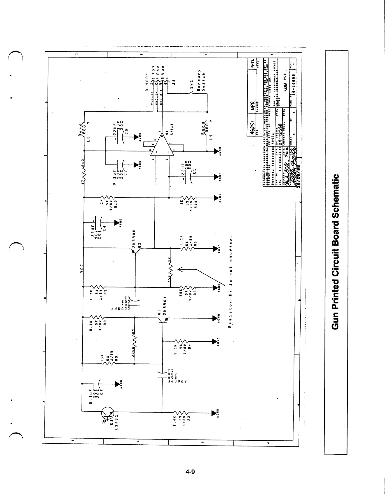
This page is a drawing, shown as the original scan.
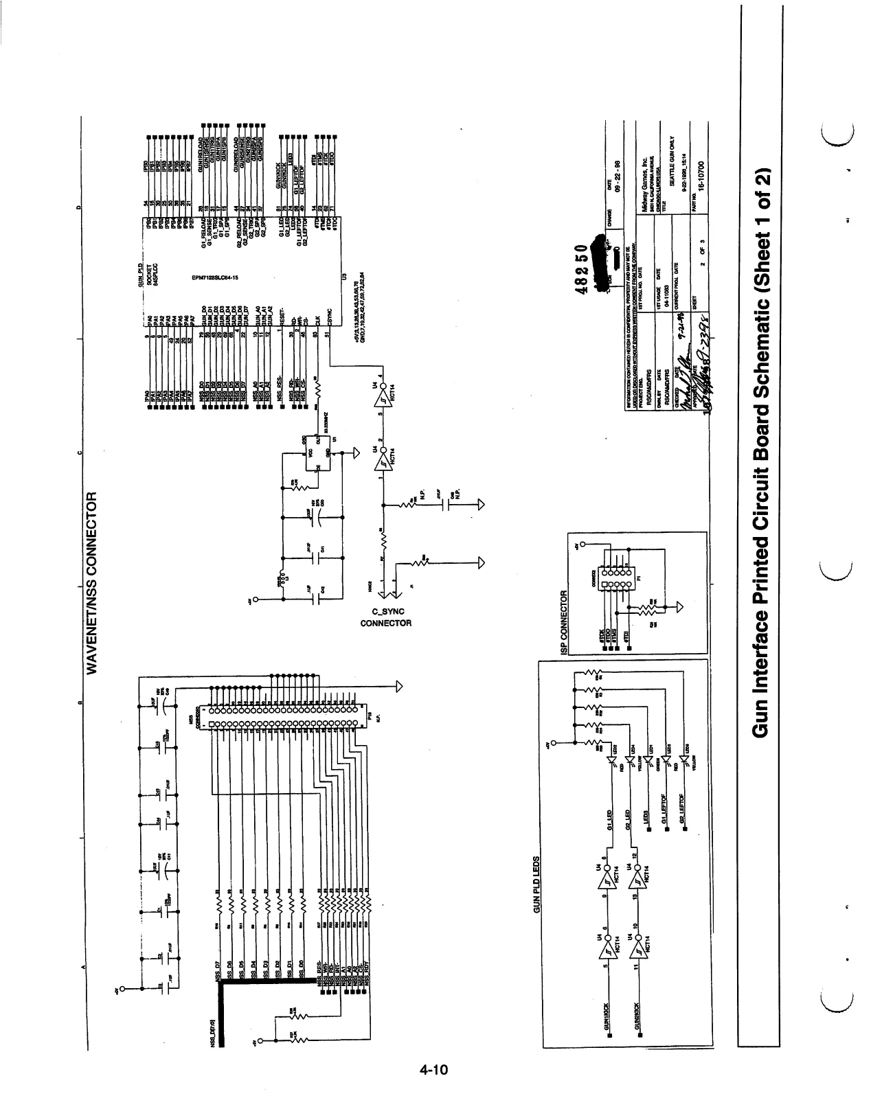
This page is a drawing, shown as the original scan.
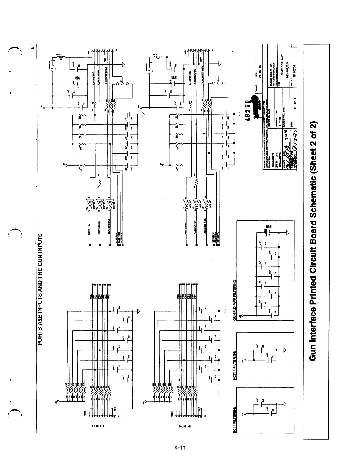
This page is a drawing, shown as the original scan.
NOTES
CARNEVIL..
SECTION
FIVE
TROUBLESHOOTING
- Before servicing electronics, turn off A.C. power to the game. Wait for capacitors to discharge.
- BEFORE touching or handling electronic assemblies, discharge static electricity on your body. To discharge this static, begin by connecting the line cord to a properly grounded outlet. Don’t turn on the game! Next, touch the safety ground stud of the power supply chassis.
- Store electronic assemblies in an anti-static area. Use anti-static bags to store or transport the game CPU Board assembly. Transport the Hard Disk Drive in its container.
- DO NOT remove or connect any electronic assemblies when the cabinet power is ON. Doing so will damage electronic assemblies and void the warranty.
- Replace ground wires, shields, safety covers, etc. after you complete maintenance or service. Install and firmly tighten all ground and mounting screws.
5-1
Game Startup Troubleshooting Table
SYMPTOM REQUIRED ACTION
GAME DOES NOT START
Game appears completely non-functional.
No audio
No illumination
No video display Check that Power Switch is ON on game power supply. Turn OFF game power. Unplug A.C. line cord. Examine power supply fuse or circuit breaker. Power Line Voltage Switch must be set to agree with local A.C. line voltage. Remove line cord from power supply. Test line cord, power plug, and I.E.C. connector for breaks or damage. Verify continuity of each wire in cord. Ensure that supply connector is good. Fully seat I.E.C. connector into mating receptacle of power supply. Unlock and remove rear cabinet door. Swing door out until it rests on chains. Ensure that cabinet wiring harness connectors fully seat in corresponding power supply and CPU Board assembly. Fully seat A.C. plug in power outlet. Verify presence of A.C. line voltage. Turn game power ON. If fuse opens again, check D.C. wiring harness and connectors.
CO REMOTE ADJUSTMENT BOARD ASSEMBLY DOOR
Location of Monitor Remote Adjustment Controls
5-2
Game Startup Troubleshooting Table, continued
SYMPTOM REQUIRED ACTION
e Video game appears non- 1. Unlock and open rear cabinet door. Inspect CPU Board functional. assembly under low-light conditions. Light emitting diodes glow if processor circuits receive voltage. Fan should also be « Currency acceptor price operating. These indications prove presence of some D.C. indicator is illuminated. from power supply. Still, voltages or signals may not be normal.
- Turn OFF game power. Inspect CPU Board assembly. Ensure that JAMMA Wire Harness connector is attached and fully seated onto mating board connector. Verify connection of monitor A.C. power. Check on wiring harness connectors in same way.
- Verify that game CPU DIP Switches are set as intended.
- Turn ON game power. Using 20 Volt D.C. setting on digital voltmeter, measure D.C. voltages present at power connector pins. Adjust +5V source if necessary.
- Using 2-volt A.C. setting on digital voltmeter, measure same D.C. voltages as above. Any reading here indicates that supply voltages are unstable and may contain ripple or noise.
- Verify that game runs and completes power-up self-test sequence without any errors. Note errors or failures during these tests (Game doesn’t save error messages).
- Enter game Menu System by pressing and holding TEST MODE switch inside coin door area. Select DIAGNOSTICS from Main menu. Once in DIAGNOSTICS menu, choose MONITOR SETUP.
COIN DOOR
PRICE INDICATORS
REJECT FLAPS vevory | CIRCUITS: Seg ‘evinces FAN POWER CABLE (GUN INTERFACE CASH DOOR ee | Ate
s1e1988 WOOD PANEL
Aaa cpu" BOARD. ‘ASSEMBLY 4-11000.1 STEEL PLATE
Front View of Coin Door Interior View of Electronics
5-3
Game Startup Troubleshooting Table, continued
SYMPTOM REQUIRED ACTION
¢ Game will not accept currency or tokens and cannot be started.
e Audio and video are present. Unlock and open cash door. Empty cash box. Inspect revenue for counterfeit currency. Check vault and remove any items that block path from mechanism. Unlock and open coin door. Check each mechanism by hand to ensure proper mounting. Remove mechanism and clear currency path. Reinstall mechanism and latch it. Verify that mechanism is level when doors close. Repair or replace coin door if it is bent or damaged. If necessary, adjust cabinet leg levelers to keep mechanisms vertical.
¢ Game accepts currency or tokens, but does not start.
e Audio and video are present. Unlock and open coin door. Check each currency acceptor by hand to ensure proper mounting. Verify that each of release latches is in closed and locked position. Test known good and bad coins to see if mechanism accepts and rejects currency correctly. Ensure that no loose parts or wires are caught in hinges, latches, or switch contacts. Inspect to see if external acceptor indicators (Pricing, Flashing Arrows, etc.) are illuminated. Check connectors and cables for wiring continuity from CPU Board connectors to acceptors. Enter game Menu System by pressing and holding TEST MODE switch inside coin door. From DIAGNOSTICS menu, choose SWITCH TESTS. Use these tests to confirm operation of each switch used in game. Check for continuity in each of suspect switch connections (Common to Normally Open or Common to Normally Closed). Replace faulty switches (bent levers, broken actuators, etc.). Verify that each acceptor is operating properly by placing it in known good unit.
[— COIN MECHANISM
p——COIN DOOR
Interior View of Coin Door and Cash Door
5-4
Game Startup Troubleshooting Table, continued
non-functional.
e Game starts normally. SYMPTOM REQUIRED ACTION
e Player controls are Unlock and open coin door. Enter game Menu System by intermittent or completely pressing and holding TEST MODE switch inside coin door. From DIAGNOSTICS menu, choose SWITCH TESTS. Use these tests to confirm operation of each switch used in game. Unlock and open coin door. Ensure that no loose parts or wires are caught in hinges, latches, or switch contacts. Verify that harness connectors are attached and fully seated. Check that cabinet wiring is correct for this game. Ensure that control switches connect properly to control input wires from P3, P16 and JAMMA connector. Verify continuity in each of switch connections (Common to Normally Open or Common to Normally Closed). Ensure that control is operating properly by placing in known good unit. Guns malfunction or don’t work: See Shotgun Troubleshooting Table. Game accepts currency or tokens, but number of credits per coin or bill is incorrect. Unlock and open coin door. Enter game Menu System by pressing and holding TEST MODE switch inside coin door. From DIAGNOSTICS menu, choose SWITCH TESTS. Use these tests to confirm operation of each switch used in game. From ADJUSTMENTS menu, choose PRICING to verify units and credits are set correctly. Check that cabinet wiring is correct for this game. Ensure that coin meter and coin switches connect properly to control input wires from JAMMA connector and or CPU wiring.
5-5
Shotgun Troubleshooting Table
SYMPTOM REQUIRED ACTION
e Players complain that one or both guns fail to hit targets
e Game starts normally Turn off room lights to eliminate glare on monitor. Unlock and open coin door. Enter game Menu System by pressing and holding TEST MODE switch inside coin door. From DIAG- NOSTICS menu, choose GUN TEST. Use Targeting subtest to confirm accuracy of each gun. Retest guns with lights on. From UTILITIES menu, choose RECALIBRATE. Use GUN CALIBRATION screen to reset each gun’s aim. Stand directly behind gun holder and extend cable to its full length to ensure greatest accuracy. Inspect each gun for missing screws, loose or damaged parts, broken cables, etc. Examine gun barrel and lens for dirt or debris. Do not apply cleaner directly into gun barrel. Unlock and open coin door. Ensure that no loose parts or wires are caught in hinge or switch contacts. Check gun cable ground connections. Verify that harness connectors are attached and fully seated. Verify that each gun assembly operates properly by placing it in known good unit. © Guns are intermittent or completely non-functional
e Game starts normally. Check gun fuses on Gun Interface Board inside main cabinet. Each gun has its own fuse. Enter game Menu System by pressing and holding TEST MODE switch inside coin door. From ADDITIONAL ADJUSTMENTS menu, choose FLASH BRIGHTNESS. This feature may be set too low. Factory recommended setting is .50. Increase setting and retest shotguns. (NOTE: GAMMA setting on Gun Test performs same function as FLASH BRIGHTNESS.) Remove screws from gun. Separate pieces at handle end first, using care not to dislodge parts. (Trigger is spring loaded.) Check gun board, switches and switch connectors. Clean lens to remove fingerprints and dust. Reinstall shields removed during disassembly. After you reassemble gun, verify that good connection exists between static shield and cable ground. Verify that each gun assembly operates properly by placing it in known good unit. lf gun still doesn’t work, gun circuit board may be bad. Troubleshoot or replace board and retest gun.
SIGHT
e HANDLE Shotgun Parts
PUMP. GUARD | TRIGGE! e@ @
S\=METAL CABLE
Audio Troubleshooting Table
SYMPTOM REQUIRED ACTION
*¢ No audio
e Video is present
- Game appears to operate normally Unlock and open coin door. Enter game Menu System by pressing and holding TEST MODE switch inside coin door. From Main Menu, choose VOLUME LEVEL. Verify that volume levels have not been set at zero. Change levels if necessary to make game audible. From ADJUSTMENTS menu, choose ATTRACT SOUND to see if this feature is active (ON). Follow on-screen instructions to return to first menu. Select DIAGNOSTICS from Main Menu. Once in DIAGNOSTICS menu, choose SOUND SUBSYSTEM. These tests confirm operation of each segment of sound system. Turn off game power. Remove grilles and inspect speakers. Free speaker cones, terminals, mounting screws and magnets of loose parts or wires. Verify correct cabinet wiring for this game. Ensure that speakers connect properly to audio output wires from JAMMA connector. Verify that each speaker has continuity. Turn on game power. Using 20 volt D.C. setting on digital voltmeter, measure D.C. voltages present at power connector pins. Verify +5V, -5V and +12V sources. Using 2 Volt A.C.-setting on digital voltmeter, measure same D.C. voltages as above. Any reading here indicates that supply voltages are unstable and may contain ripple or noise. Verify proper operation of game CPU Board assembly by placing it in known good game.
5-7
Audio Troubleshooting Table, continued
e Constant low hum may be present. SYMPTOM REQUIRED ACTION
e Audio is distorted, muffled or Unlock and open coin door. Enter game Menu System by missing frequencies. pressing and holding TEST MODE switch inside coin door. From Main Menu, choose DIAGNOSTICS from Main Menu. Once in DIAGNOSTICS menu, choose SOUND SUBSYSTEM. These tests confirm operation of each segment of sound system. Turn off game power. Remove grilles and check speakers. This game uses two coaxial speakers. Ensure that speakers are FULL RANGE (100 to 10,000 Hz response) and rated for at least 20 WATTS. Check for reversed wires at one speaker. Weak low frequencies and thin or hollow sound quality is symptom of incorrectly phased speakers. This condition may not be detected by SOUND SUBSYSTEM, but it will be audible during normal game operation. Check that cabinet wiring is correct for this game. Verify that cabinet wiring provides separate wires (not common return) for each speaker. Check connection of all cabinet ground wires. Using 2 Volt A.C. setting on digital voltmeter, measure voltages at speaker terminals. Any reading here indicates that supply voltages are unstable and may contain ripple or noise. Verify that speaker operates properly by placing in known good unit.
5-8
Video Troubleshooting Table
SYMPTOM REQUIRED ACTION
| « | Monitor appears non- | 1. | Unlock and open rear cabinet door. Verify connection of A.C. |
functional Power to Video Monitor. Inspect CRT neck under low light conditions. You'll see glow near CRT base if voltage appears
| e | Audio is present | across filament circuits. This indication proves that some |
monitor circuits receive power. Still, voltages or signals may not
| ¢ | Controls operate as | be normal. |
expected 2. Turn off game power. Verify that Video Signal and Remote Adjustment Board connectors seat properly on Video Monitor Board assembly. Check other monitor connectors in same way.
- Examine A.C. line fuse on Video Monitor Board assembly. If fuse is faulty, replace it with an identical fuse of proper voltage and current rating.
- Ensure that no loose parts or wires are caught on chassis or mounting brackets.
- Check that brightness (intensity) and contrast have not been set to their minimum levels.
- Verify that Video Monitor operates correctly by placing it in known good unit.
BASE OF CRT
NECK BOARD ‘ASSEMBLY
MAIN. VIDEO BOARD ASSEMBLY
REMOTE ADJUSTMENT BOARD ASSEMBLY
Cutaway Rear View 5-9
Video Troubleshooting Table, continued
SYMPTOM REQUIRED ACTION
| ¢ | Game does not appear | 1. | Note and record any error messages that occur during self- |
test. Open coin door. Press and hold TEST MODE switch to
| ¢ | No audio is present | enter menu system. Select DIAGNOSTICS from Main Menu. |
Once in DIAGNOSTICS menu, choose DISK TESTS. Use this
| ¢ | Power-up self-test runs | | | set of tests to check operation of critical components. |
- Turn off game power. Unlock and open front door. Inspect CPU Board assembly. Ensure that JAMMA cable connector seats properly into mating edge connector on CPU Board. Check cable connectors for correct alignment and continuity.
- Verify that ROM instruction set is correct for this game. Game set includes more than one ROM. Each ROM circuit is labeled with assembly number and software version.
- Verify that CPU Board assembly is correct for this game. Each CPU Board is marked with manufacturer name, assembly number and hardware version.
- Verify that hard disk drive assembly is correct for this game. Each hard disk drive unit is marked with manufacturer name, assembly number and program version.
- Turn on game power. Using 20 Volt D.C. setting on digital voltmeter. Measure D.C. voltages present at power connector pins. Verify +5V source if it is adjustable.
- Using 2 volt A.C. setting on digital voltmeter, measure same D.C. voltages as above. Any reading indicates that supply voltages are unstable and may contain ripple or noise.
- Compare CPU Board jumper positions with CPU Jumper Status Chart (Section Four). Compare CPU Board light emitting diode states with CPU Indicator Chart (Section Three).
NOTICE: Before adjusting the monitor, demagnetize the CRT with an industrial grade degaussing coil.
5-10
Video Troubleshooting Table, continued
SYMPTOM REQUIRED ACTION
© Monitor will not lock onto signal and provide stable picture
e Colors are missing, etc. Unlock and open coin door. Enter game Menu System by pressing and holding TEST MODE switch inside coin door. From DIAGNOSTICS menu, choose DIP-SWITCH TESTS. Verify that GRAPHICS MODE is correct. Check connectors and cables for wiring continuity from CPU Board to video monitor. Ensure that video monitor assembly is correct for this game. Use of video monitors with different resolution will result in horizontal tearing or complete loss of sync. Verify that video monitor operates correctly by placing it in known good unit. © Game operates normally
e Video wavers or rolls, has dark bars, uneven colors, etc. Check connectors and cables for wiring continuity from CPU Board to video monitor. Ensure connection of all cabinet ground wires, especially at video monitor chassis. Move cabinet far away from machines, appliances, or games, etc. During normal operation, some equipment emits very strong electrical or magnetic fields. Verify that video monitor operates correctly by placing it in known good unit.
Software Update Troubleshooting Table
SYMPTOM REQUIRED ACTION
| e | Update did not work | 1. | You skipped steps or performed them out of sequence. This kit |
and its instructions resemble other game updates, but updates
| e | After update procedure, | aren’t identical. Return update components to kit, reinstall |
screen reports lower than original parts in cabinet, and try process again.
| latest version | 2. | You connected linked games to cabinet being updated. |
Network communication circuits may have prevented a full update. Turn off power to all connected cabinets. Then perform update on only one cabinet at a time. You need not disconnect linking cables.
- An installation error may have damaged a device. Inspect for bent or broken pins. If you have another kit, try it. Your distributor can check your EPROMs.
| e | Game does not recover | 1. | Boot Update version and hard disk drive don’t match. Once |
you've updated disk drive, CPU instructions must be at correct
| e | Board indicators illuminate, | version to make use of new data stored on disk. Be certain that |
but screen is completely boot ROM device resides in socket U32.
| blank | 2. | You may have installed devices in wrong sockets. Only use |
socket U33 for hard disk drive updates. During game play, socket U33 must be empty. After you install disk ROM and load its contents onto drive, remove it from game.
NOTICE: Someday, software updates for your game might become available. These upgrades may improve your game's performance or add new game features. Such upgrades tend to appear sometime after the factory first releases a game. Contact your distributor for information about updates.
5-12
Miscellaneous Problem Troubleshooting Table
SYMPTOM REQUIRED ACTION
¢ Marquee lamp is intermittent or non-functional
e Game starts and plays normally. 1. Open front door and formed housing. Remove fluorescent tube from its sockets. If your find cracks or darkened ends, install new lamp. Clean tube. Verify that lamp pins make good connection with socket contacts. Measure fluorescent lamp assembly A.C. voltages. Check wiring and connector continuity from power supply connector to lamp assembly. Check continuity of both fluorescent lamp filaments. Verify that lamp operates by placing it in known good unit. ¢ Game operates normally
e Fanis noisy ep Check bottom and rear of cabinet for blocked air flow. Move game away from sources of heat. Turn off game power. Apply high power vacuum cleaner to vent holes to remove dust. Unlock and open front door under monitor. connection and operation of all fans. e Error Messages appear on screen
¢ Game does not start and has no audio. Check any assembly (RAM, ROM, Battery, etc.) identified in error messages. Call your authorized distributor for help with unresolved screen messages.
5-13
This page carries no recoverable text. It is a drawing or a photograph. See the original scan.
This page carries no recoverable text. It is a drawing or a photograph. See the original scan.
WARNINGS & NOTICES
- For safety and reliability, substitute parts and modifications are not recommended.
- Use only authorized components and parts. Failure to do so will void warranty and may result in incorrect and/or unsafe operation. Substitute parts or modifications may void EMC directive or FCC type acceptance.
- This game is protected by Federal copyright, trademark and patent laws. Unauthorized modifications may be illegal under Federal law. This also applies to MIDWAY GAMES INC. and CARNEVIL logos, designs, publications and assemblies. Moreover, facsimiles of MIDWAY equipment (or any feature thereof) may be illegal under federal law, regardless of whether or not such facsimiles are manufactured with MIDWAY GAMES INC. components.
WARNING *
A very small portion of the population has a condition which may cause them to experience epileptic seizures or have momentary loss of consciousness when viewing certain kinds of flashing lights or patterns that are present in our daily environment. These persons may experience seizures while watching some kinds of television pictures or playing certain video games. People who have not had any previous seizures may nonetheless have an undetected epileptic condition.
If you or anyone in your family has experienced symptoms linked to an epileptic condition (e.g. seizures or loss of awareness), immediately consult your physician before using any video games.
We recommend that parents observe their children while they play video games. If you.or your child experience the following symptoms: dizziness, altered vision, eye or muscle twitching, involuntary movements, loss of awareness, disorientation, or convulsions, DISCONTINUE USE IMMEDIATELY and consult your physician.
When MIDWAY GAMES INC. ships a game, it is in compliance with FCC regulations. Your label is proof of compliance. Legal repercussions to the owner or distributor may result If the label is missing or damaged. If your game does not contain an FCC compliance label, call MIDWAY GAMES INC. immediately.
NOTICE No part of this publication may be reproduced by any mechanical, photographic, or electronic process, or in the form of a phonographic recording, nor may be transmitted, or otherwise copied for public or private use, without permission from the publisher.
MIDWAY® and CARNEVIL™ are trademarks of MIDWAY GAMES INC.
For Service: Call your Authorized MIDWAY GAMES INC. Distributor.
MIDWAY GAMES INC. 3401 N. CALIFORNIA AVE. CHICAGO, ILLINOIS 60618-5899 USA
Entire contents of this manual copyright © 1998 MIDWAY Games Inc. All rights reserved. W)
WJ