Strike Force Conversion Kit
Strike Force (rev 1 02/25/91) (Midway, 1991) · Kit Manual · 51 pages · 42 sections · original scan
ectatetcecevectctctrecececec ects tert tc tebe tr tztytety etatetetetetetatatetetetetetetetetetetetetecececten! Colo oo of of oo ooo CHIH EOC COO COC ECO C OOOO CGE
Chicago, IL 60618 MIDWAY MANUFACTURING 3401 N. California Avenue
including
OPERATIONS MANUAL
Testing & Problem D
Installation & Operation
iagnosis
PC Board Parts Information
Reference Diagrams & Schematics OOOOH HY Co 6, 6.6.6.6. 6.6.6.6. 6, etotatetetetatatetetetent OOOO > 6,6, 6.0. 6.6.6.6,6.6.6.6. 6, 6,6, 6. 6.6.6.6.6.6.6.6.6.6, etetetetetetetetatetatetet 16-43113-101 March 1991
The Saga of STRIKE FORCE
In the year 2020 the first alien contact is made. From the farthest reaches of the galaxy comes a distress call, The Saurians, an evil reptilian race bent on conquering the universe, are currently invading the human colonized Beta System. The Saurians mutate all life forms they encounter into slaves for their evil empire. The only hope for the colonists and, perhaps, all of mankind is an elite team of fighters able to respond to the initial invasion.
Each player controls a Strike Force composed of a rocket fighter and a team of space marines in their powered battle armor. They must travel throughout the planets of the Beta System, battling the Saurians and their vicious minions. Unfortunately, defeating the Saurians on the planets surface is not enough, The Saurian megastar, which brought the alien invaders, is circling the solar system launching dreadnaughts, These large dangerous motherships travel to the planets delivering a never- ending supply of invading Saurians. The players need to destroy the dreadnaughts to prevent the retaking of their hard won planets. Ultimately though, they must attempt the destruction of the Saurian Megastar “Apocalypse” to end the invasion and win on the Saurian Front.
STRIKE FORCE
Game Play
STRIKE FORCE is a one, or two-player game in which two players play simultaneously. Unlimited buy-ins are allowed at any time for either player. STRIKE FORCE is unique because it has unlimited open ended game play and an ultimate goal, which allows the players to win. Most games provide the player with a fixed series of encounters that do not change from game to game, STRIKE FORCE puts the player in charge of battling his/her way through a realistic environment. The player not only chooses where to go across a 3D- looking planetary surface, but also which weapon to use from an arsenal that accumulates as the game progresses. Once the Saurians are conquered on a planet, the player pilots his/her interplantary shuttle to one of 22 different planets.
The Megastar is 40 screens long. The ultimate challange of STRIKE FORCE is to chase down, enter, and get to the core of the enemy Megastar.
STRIKE FORCE
TABLE OF CONTENTS
Section 1 Installation and Operation Safety Conversion Procedure Inspection Recommended Tools and Supplies Cabinet Modifications Control Panel Modifications Typical Control Panel Layout Installing PC Boards & Wiring into a JAMMA Cabinet 1-46 Installing PC Boards & Wiring into a non-JAMMA Cabinet1-7 Installing the Volume Control Game Features Start-up Player Controls Game Operation Control Switches Control Switch Location Diagram Game Audits, Diagnostics & Adjustments Operation Game Audits Audit Table Diagnostic Tests CPU Test Burn-in Test Monitor Test DIP switch Test Switch Tests Game Adjustments DIP switch 1 DIP switch 2 Troubleshooting
Section 2 PC Board Parts Information
CPU Board CPU Parts Sound Board & Parts
Sound Board Schematic CPU Board Schematic JAMMA Chart Cabinet Wiring Coin Meter Wiring Interboard Wiring Control Panel Wire Colors Control Panel Template Diagram
COPYRIGHT 1991 MIDWAY Manufacturing ALL RIGHTS RESERVED 1-9 1-9
1-10 1-10
1-11 1-11 1-11 1-12 1-12 1-12 1-12 1-12 1-12 1-13 1-13 1-14 1-15
2-2 2-3 2-4
3-2
3-19 3-20 3-21 3-22
3-25
SECTION
one
INSTALLATION and OPERATION
Safety Notices
The following safety hints apply to all kit operators and service personnel. Specific warnings and cautions will be found throughout this manual where they apply. We recommend that you read this page, and also all of Section 1, before preparing your kit for play.
NOTICE: SALVAGED PARTS Parts salvaged from old games are required to complete your kit. These salvaged parts must operate perfectly: otherwise, the converted game cannot perform properly or safely. Always repair circuit board malfunctions and cabinet damage before conversion is attempted.
NOTICE: POWER SUPPLY Be sure the power supply from your old game is capable of +5V de at 5A, -5V deat 1Aand+12Vat 1A. These operating voltages are necessary for your kit. Your power supply must be FCC approved.
NOTICE: MONITOR This kit is not intended for use with X-Y monitors. Suitable monitors have horizontally mounted CRTs and raster electronics with inputs for red, green and blue video, as well as Composite Negative Sync inputs,
NOTICE: COIN MECHANISM Be sure to clean and lubricate your old coin mechanisms. Servicing them is crucial to your game's earning potential and operation.
NOTICE: COIN METERS Coin meters are not provided with this kit. Wiring information is provided as a convenience to the operator.
NOTICE: SERVICING, INSTALLING Always turn your game Offand unplugit before attempting to service or install your kit.
PROPERLY ATTACH ALL CONNECTORS. Be sure that the connectors on each printed circuit board (PCB) are properly connected. Ifthey donot slip on easily, donot force them. Areversed connectormay damage your kit and void the warranty. Allconnectors are keyed to fit specific pins on each board.
1-2
Conversion Procedure
Inspection Unpack the materials from the carton and inspect for obvious signs of damage. Use this checklist to be sure your kit is complete.
Part No. Item Quantity
| [] | A-13234-43313 | CPU board | 1 |
| [] | A-13971-43313 | Sound board | 1 |
| [] | C-9214-4 | red pushbutton assy | 2 |
| [] | C-9214-22 | purple pushbutton assy | 3 |
| [] C-9214-23 | yellow pushbutton assy | 3 | |
| (] | H-8866 | volume control cable | 1 |
| (] H-12758 | sound board jumper cable | 1 | |
| [] | H-13257 | sound power/speaker cable | 1 |
| (] | H-13411 | main JAMMA cable | 1 |
| {] 16-9201 | controls template | 1 | |
| (] | 16-43113-101 | manual | 1 |
| [] | 20-9222 | 5/8 palnut | 8 |
| {] | 20-9319-4 | yellow 8-way joystick | 1 |
| [} | 20-9319-6 | purple 8-way joystick | 1 |
| (] | 20-9457 | Wico buttonholder | 8 |
| [] | 31-1613-42413 | kit marquee | 1 |
| [] | 31-1616-42413 | cabinet side decal set | 2 |
| (] | 31-1620-42413 | control panel overlay | 1 |
| [] | 31-1622-42413 | contro] panel decal | 1 |
| [] | 5795-10937-18 | 20-pin ribbon cable | 1 |
[] assorted hardware
Recommended Tools and Supplies (] black semi-gloss paint (J electric drill [J electric screwdriver [] grease pencil or marker (J hex driver [] 180 grit sandpaper or electric sander [] pliers [] razor knife {] soldering iron and solder (] wire cutters [ ] black electrical tape (] quick-hardening wood putty
1-3
Cabinet Modifications
1, Fill in gouges with a good quick-hardening wood putty. Sand cabinet and wipe it clean.
- Repaint the cabinet with black semi-gloss paint (Games wood grain sides: remove the old decals and clean the glue residue from the old decal before painting). Allow paint to dry completely.
- Pencil a line roughly at the top of the old graphic. Lightly moisten the cabinet with soapy water. Apply the decal starting at the top and working down. After the decal is in place, smooth it down, taking care to squeeze out the air bubbles. If you miss an air bubble, pop it with a razor blade orapinand burnish it down. Allow 12 hours forthe adhesive in the decals to set. Remove masking.
4, Check the Strike Force Kit for an FCC sticker and apply it over the existing sticker on the cabinet.
When Midway ships a game, it is in compliance with FCC regulations. Your sticker is proof. If the sticker is missing or damager, legal repercussions to the owner or distributor of the game may result. If your game kit does not contain an FCC sticker, call Midway Manufacturing immediately.
- Apply the Instructions (Card or Decals) to the CRT viewing glass.
Control Panel Modifications
- Remove the control panel buttons and joysticks and remove the old vinyl covering.
- Use the Control Panel Template to help you design your control panel. You will need to use the template twice, once for the left side and once for the right side of the control panel.
- Drill holes as needed for the joysticks and buttons. Plug previous holes with wood blocks, putty, cardboard or epoxy. File the new holes smooth.
- Carefully remove the backing on the vinyl control panel overlay. Place the overlay on top of the control panel. Prevent air bubbles from getting under the vinyl overlay.
- a) After the overlay is on securely, use a razor knife to cut holes for the buttons and joysticks.
- Position the stickers around the appropriate button locations. Refer to the Typical Control Panel Layout diagram for suggested button and joystick locations.
- Tomount the pushbuttons and button-holder/switch to the control panel, push the threaded end of the pushbutton through the control panel from the top so that the threads extend through the back of the control panel. Then, take the white plastic button holder/switch and place it over the pushbutton threads so that the threads extend through the hole in the holder. The blade switch must point toward the back of the cabinet and face you. Secure into place witha palnut. Repeat for all of the pushbutton switches.
- To mount the joystick assembly to the control panel first position the switch assembly so that the square base is against the back of the control panel and the hole in the base lines up with the joystick hole in the control panel. Secure the switch assembly to the control panel. Be sure that one of the blade switches faces the monitor when the control panel is closed. Remove the "E"-ring, white plastic spacer and spring from the joystick shaft. Slip the black plastic washer around the joystick shaft so the rough side faces the handle. Push the shaft through the joystick base from the front of the control panel. After the shaft is through the base, replace the spring, spacer and "E"-ring.
Joystick Start/Transform Joystick Start/Transform © © Fire Weapon Fire Weapon
Weapon Select
TYPICAL CONTROL PANEL LAYOUT
1-5
If you choose to use your own JAMMA Cable and not the one provided in the kit, be sure to check the JAMMA Cable Chart to verify that it is compatible.
Properly insulate any unused wires within the JAMMA cable, especially the gray, graygreen and gray-yellow wires. This is a fully wired JAMMA cable, Many of the wires will not be used for this kit. These wires have been installed so that you can use this cable for future kits.
The ribbon cable may need to be twisted in order to connect it properly. Installing the PC Boards and Wiring into a JAMMA Game Cabinet
- Disconnect and remove the existing CPU board in the JAMMA game cabinet.
- Mount the Strike Force CPU board inside the JAMMA game cabinet where the old CPU board was located. Mount the sound board next to the CPU board using the stand-offs and screws provided.
- Ifyou choose to use the JAMMA cable provided with the kit, unsolder your old JAMMA cable from the speaker, power supply, control panel switches (which may already be disconnected) and coin door. Remove the cable from the game. If you are not going to use the JAMMA Cable provided with the kit, check the JAMMA Cable Chart to be sure your cable is compatible. Leave your power supply chassis as is.
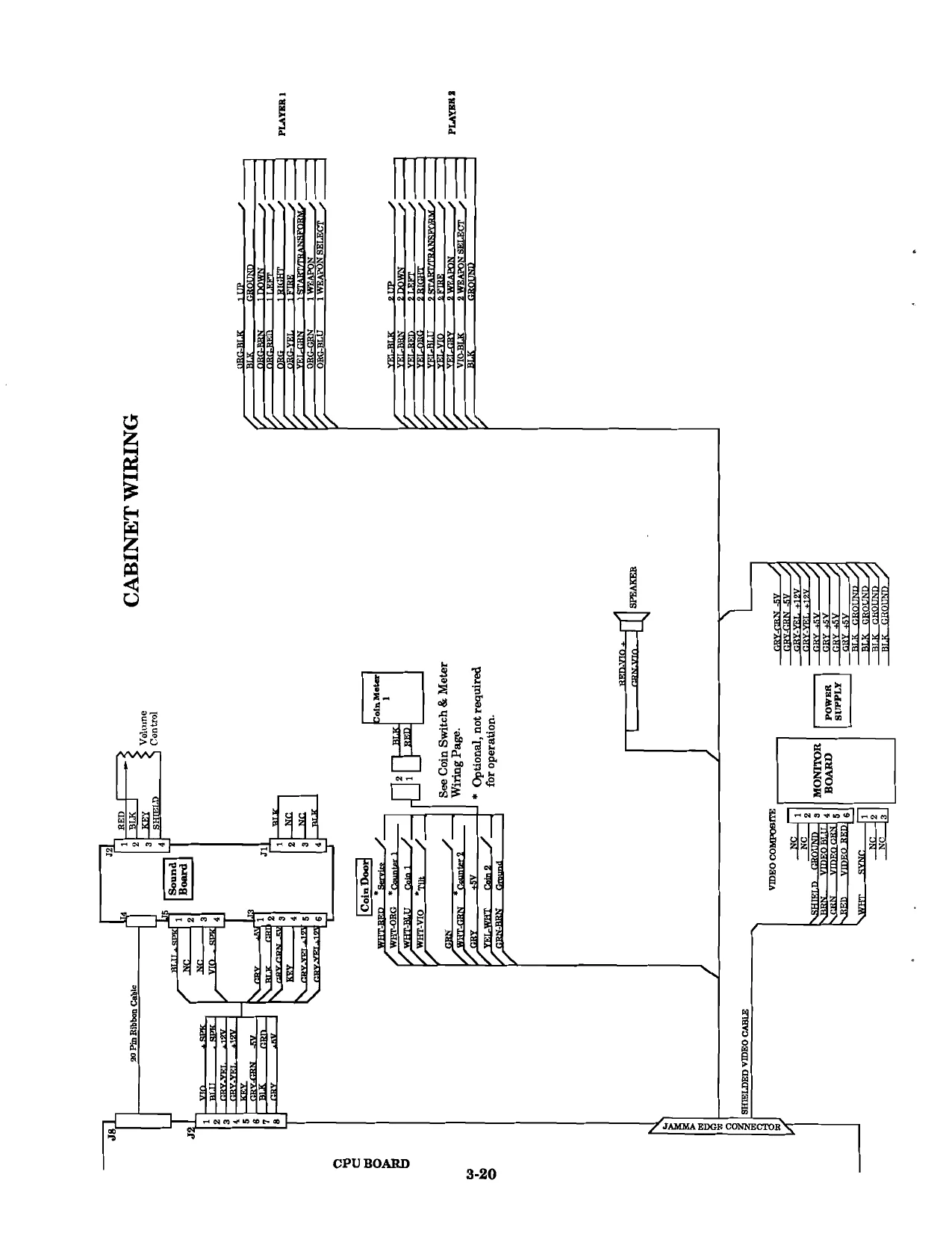
- Connect the JAMMA cable to J1 on the Strike Force CPU board. Using the JAMMA Cable Chart or the Cabinet Wiring Diagram for reference, solder the correct JAMMA cable wires to the speaker, power supply, coin door, control panel switches, and joystick switches. When soldering the joystick switches, be sure to connect the correct wire to the correct blade switch. Follow the Control Panel Wire Color List (pg.3-23), or the Cabinet Wiring Diagram (pg. 3-20).
- Connect the ribbon cable from J4 on the sound board to J8 onthe CPU board. Be sure that the red line goes to the same pin on both boards. Connect the wire harness cable from J5 (speaker), and J3 (power), on the sound board to J2 (sound power speaker connector) on the CPU board.
- J6,J7, J9, J12 and J14 on the CPU board are not used.
- Place the FBI Warnng Label on the inside of the cabinet next to the PC boards. Be sure the label is completely visible.
1-6
Installing the PC Boards and Wiring into a NON-JAMMA Game Cabinet.
- Disconnect and remove the existing CPU board in the game cabinet.
- Mount the Strike Force CPU board inside the game cabinet where the old CPU board was removed. Mount the sound board next to the CPU board using the stand-offs and screws provided.
- Leavingseveral inches of wire, cut the wires at the coin door, control panel switches (which may already be disconnected) speaker and power supply. 4, Connect JAMMA cable to CPU board at J1. Follow the JAMMA Cable Chart or the Cabinet Wiring Diagram and splice the wires of the JAMMA cable to the existing wires for the coin door, power supply, speaker, control panel switches and joystick switches. When soldering the joystick switches, be sure to connect the correct wire to the correct blade switch. Follow the Control Panel Wire Color List (pg. 3-23), or the Cabinet Wiring Diagram (pg. 3-20). Besureallof the spliced wires are well insulated with black electrical tape.
- Conneet the ribbon cable from J4 on the sound board to J8 on the CPU board. Be sure that the red line goes to the same pin on both boards. Connect the wire harness cable from J5 (speaker), and J3 (power) on the sound board to J2 (sound power speaker connector) on the CPU board.
- J6,J7, J9, J12, and J14 on the CPU board are not used.
- Place the FBI Warning Label on the inside of the cabinet next to the PC boards. Be sure the label is completely visible. Be sure all spliced wires are well insulated with black electrical tape.
Properly insulate any unused wires within theJAMMA cable, especially the gray, gray-green and gray-yellow wires. Thisisa fully wired JAMMA cable. Many of the wires will not be used for this kit. These wires have been installed so that you can use this cable for future kits.
Installing the Volume Control
- Mount the volume control, using screws provided, where itis easily accessible. On top of the cash box, or on the wall near sound board are two possible locations.
- The volume control cable attaches the volume control to the sound board at connector J2. When viewed with the white plastic knob facing you, the shield wire should be soldered to the right lug, the red wire should be soldered to the middle lug, and the black wire should be soldered to the left lug.
Volume Control Wiring
Diagram
Red Black Shield
(©)
Game Features
Start Up
Switch On power to the game. A "rug” pattern appears on the CRT screen. When the "rug" pattern ends, the screen shows CHECKING SCRATCH RAMS, and then CHECKING ROMS. The next screen shows REVISION LEVEL, CMOS TEST OK and the COIN SETTING. The game then moves to the attract mode. After the proper coinage has been inserted, the game exits the attract mode and enters the play mode.
Player Controls
Each player has an 8-way joystick and four buttons. The joystick controls the movement of the ship. The buttons are Start/ ‘Transform, Fire, Weapon and, Weapon Select.
Each START/TRANSFORM button is used to start or continue a game. Ifa gameis in progress, this button toggles the player between ship and turret modes. The ship is more mobile than the turret, but the turret has better firepower. Duringa 2-player game, ifone player is the ship and the other player is the turret, the turret is docked onto the ship unless the player does a quick double-click on the START/TRANS- FORM button when transforming. E
Each FIRE button is used to fire the player's standard weapon. Whenthis button is held down, the weapon goes into rapid-fire mode. The Rapid Fire Counter is incremented by 100 each time a Rapid Fire Icon is picked up. The greater the Rapid Fire Counter value, the faster the weapon fires.
Each WEAPON button is used to fire the special weapons in the player's arsenal. The player is awarded special weapons bystarting or continuing a game, by finding them on the planet's surface or, by rescuing colonists. When two players are docked together, they are both awarded a picked up weapon. There are over twelve weapons to discover and master.
f§ Each WEAPON SELECT button is used to select weapons inthe player's arsenal. Players accumulate weapons and use them as needed. The weapon currently being used is in a flashing box. Each time the WEAPON SELECT button is pressed, the current weapon moves to the end of the arsenal and the rest of the weapons are shifted one to the left. The game announces the name of the chosen weapon so the player knows what is selected without watching the arsenal. It’s helpful to keep the sound level loud enough to hear the game's speech clearly.
1-9 STRIKE FORCE is a one or two player game that allows two players to play simultaneously.
When an error is detected during Start-up Tests, game start-up does not progress, and an error message appears on the screen.
Game Operation
STRIKE FORCE is a one- or two-player video game with a color monitor. From the player's perspective, the game has two modes of operation: Ready-to-Play and Play. For the owner/ operator, the game has an additional mode of operation called Game Diagnostics and Adjustments.
Control Switches
[& The SLAM TILT SWITCH detects any forceful vibrations against the Coin Door. This eliminates pounding for free games. (optional switch)
—§ The VOLUME CONTROL allows increasing or decreasing the sound level of the game's music and speech. For greater earnings, set your game's sound level at its maximum.
The TEST/DIAGNOSTICS SWITCH allows you to enter the Game's Diagnostics mode. Move the Test Switch left to enter the Game Diagnostics mode. To exit this mode, move the Test/Diagnostic Switch right. (optional switch)
TheSERVICE CREDIT SWITCHisaspecial-feature switch that provides credits during game testing without affecting the game's bookkeeping total. (optional switch)
Slam Tilt
Typical Control Switch Locations
1-10
Game Audits, Diagnostics & Adjustments
Operation
All Game Audits and Diagnostics are accessible through the Test/Diagnostic switch if you have installed it, or the DIP switches located on the CPU board, if you have not. Game Adjustments are set or changed using the DIP switches.
GAME AUDITS To access the Audit Table, move the Test/Diagnostic switch to the left. If you have not installed a Test/Diagnostic switch, then turn On switch #1 on DIP switch #2 To clear the Audits, move both joysticks toward the center of the Control Panel.
To exit the Game Audit Table, move the Test/Diagnostic switch to the right, or turn Off switch #1 on DIP switch #2.
AUDIT TABLE
Audit Value
Left Chute (# of left chute coins) Right Chute (# of right chute coins) Center Chute (# of center chute coins) Fourth Chute (# of fourth chute coins) Service Credits (# of service credit coins) Credits Played (# of credits played - sum of starts and continues) Player 1 Starts ( # of times player 1 started a game) Player 2 Starts (# of times player 2 started a game) Player 1 Continues (# of times played 1 continued a game) Player 2 Continues (# of times player 2 continued a game) One Player Seconds (# of seconds for one player game) Two Player Seconds (# of seconds for two player game) Plays to High Score Reset (# of plays without making HS. until reset) Average Seconds per Credit ( average # of seconds played per coin) Burn-in Loop (# of Burn-in loops completed) Credits (# of unplayed credits available) Idle Minutes (# of idle minutes) Wins (# of games played to completion; starbase destroyed) ecoococooooCOooCOoCOCOSO
1-11
There are front- mounted monitor controls (beneath the monitor and within the control panel opening) for easier monitor adjustments.
Adjust the black level to just before the black portion turns gray. Adjust the contrast tojust before the text starts to blur. DIAGNOSTIC TESTS To access the Tests/Diagnostic Mode, first move the Test/Diagnostic switch to the left, or turn On switch #1 on Dip switch #2. The Audit Table is shown.
To exit the Test/Diagnostic Mode from any test, move the Test/ Diagnostic switch to the right, or turn Off switch #1 on DIP switch #2.
CPU Test To enter the CPU Test from the Audit Table press the Player 2 ‘Weapons Button.
The CPU Test allows the operator to check the game's memory RAM and program ROM chips. The screen shows the layout of the RAMs and ROMs onthe CPU board. A good chip turns green. A faulty chip turns red. Ifno error is found the test cycles back to the Audit Table.
Burn-in Test To access this test from the Audit Table, press the Player 1 Weapons Button.
The Burn-in Test repeats some of the Diagnostic Tests continually. When the Burn-In Test detects a error, the test stops. Use this test to detect intermittent problems that may not show up during the initial tests.
Monitor Test To access the Monitor Test from the Audit Table, press the Player 1 Start Button.
This test allows the operator to check the monitor operation. There are red, green, and blue screens provided for color adjustments, as well as a crosshatch pattern for alignment adjustments.
During the Monitor Test, the colors should appear sharp and clear. The crosshatch pattern fills the screen with a grid of lines and dots. The pattern should be clear, and the dots should be round.
DIP Switch Test To access the DIP Switch Test from the Monitor Test, press the Player 1 Start Button.
The DIP Switch Test allows the operator to check the CPU board DIP switch settings.
Switch Test To access the Switch Test from the DIP Switch Test, press the Player 1 Start Button.
The Switch Test allows the operator to check the switches. Pressing a switch causes the corresponding switch location on the screen to light. Release the switch, and the screen returns to normal.
GAME ADJUSTMENTS To change the Game Adjustments, use the DIP switches on the CPU.
The Adjustments allow the operator to change the game Pricing and Difficulty levels, among other game features. Use the following DIP switch tables to change the desired adjustment.
DIP Switch 1
| swi | sw2 | sw3| | sw4]sws | swe | | sw7 |] | sws |
Difficulty
Level 1 Off On On
Level 2 Off Off On
Level 3 Off On Off
Level 4* Off Off Off
Level 5 On Off Off
Level 6 On Off On
| Level 7 | On | On | Off |
| Level 8 | On | On | On |
Ships per Credit 3 Off 4 On
Point per Extra Ship
| 40, 000 | Off | On |
| 50, 000* | Ott | Off |
| 75, 000 | On | Off |
| 100, 000 | On | On |
Start/Continue 1 credit start, 1 credit continue* Off 2 credits start, 1 credit continue On
Coin Meters Meter 1 sums all switches Off Meter 1=switch 1, (3); Meter 2=switch 2, (4) On (UK Electronic Door-Meter 1 is #10 Pence units through all switches.)
1-13
DIP Switch 2
swi swe SW3 sw4 SW5 Sw6 SWw7 sSws
. Off Game Mode’ On Test Mode
Coin Modes for Chute 1 1 coin, 1 credit* 1 coin, 2 credits 1 coin, 3 credits 1 coin, 4 credits 1 coin, 5 credits 1 coin, 6 credits 2 coins, 1 credit 3 coins, 1 credit 4 coins, 1 credit 5 coins, 1 credit
1 coin, 1 credit 2 coins, 3 credits
1-2 coins, 1-2 credits 3 coins, 4 credits
1-3 coins, 1-3 credits 4 coins, 5 credits
1-4 coins, 1-4 credits 5 coins, 6 credits
3 coins, 1 credit 5 coins, 2 credits
1 coin, 2 credits 2 coins, 5 credits Off
Off
Off
On On
On
On
On
On Off Off Off Off On On
On Off Off
Off
Off
On
On
On On On Off
On On Off
On
Off
On
On Off On Off On
On Off On Off On
Off
On
On
Off
On
Colin Modes for Chute 2 1 coin, 1 credit* 1 coin, 2 credits 1 coin, 3 credits 1 coin, 4 credits 1 coin, 5 credits 1 coin, 6 credits
UK Electronic Door chute 1 - 1 pound, 7 credits chute 2 - 50 pence, 3 credits chute 3 - 20 pence, 1 credit chute 4 - 10 pence, 1/2 credit
Free Play Off Off on On
On
On Off On On Off
On
On Off On Off On
On
Off
On
Troubleshooting
Problem
No picture, or distorted picture.
Turn game on & nothing happens.
No sound.
Move joystick and the objects do not move.
Move joystick and the objects move in the wrong direction.
Press control panel button and nothing happens.
No credit given when coins are inserted.
Too many credits for the number of coins inserted,
The game stays in the test mode. Possible Solution
Check for faulty CPU board or monitor. Check for disconnected video signal cable.
Check line fuse. Check for +5V DC at pins C, D, 3,4 of the JAMMA Connector.
Check the speaker and speaker connection to pins L and 10onJAMMA Connector. Check volume control setting. Check for +12V DC at pins F and 6 on the JAMMA Connector. Check interboard wiring from CPU board to Sound board.
Check for open wires between joystick and CPU board. Check for contamination on joystick switch contacts and CPU board pins. Check for proper ground.
Check the wiring on the joystick blade switches. Be sure to follow the Control Panel Wire Colors List or, the Cabinet Wiring Diagram when connecting the joysticks.
Check for open wires between button and the CPU board. Check for contamination on the CPU board pins or button switch blade contacts. Check for proper ground,
Check DIP switch coin setting. Check for contamination on coin switch contacts. Check for an open wire between Coin Switch 1 and pin 16 on JAMMA Connector or Coin Switch 2 and pin T of JAMMA Connector.
Check price setting. Check for a short between pins T & 16 on JAMMA Connector.
Check that the Test/Diagnostic switch and switch #1 on DIP switch #2 are Off.
1-15
NOTES
1-16
SECTION
two
PC Board Parts Information
2-1
A-13234-43313 Y-UNIT CPU BOARD ASSEMBLY
Ey Tas 1YL Ui88 37 20g) es. et im =f ties _)(_uier aa g Qe eFC cay a= Ce 20 e 2g 0 —* ; ae. toayc wee (Ce 30 : ==
c
i a aa ree) (weg sh es Kj zl = — ho = TM = —T. (are) asa) Carp any 1 a | Cows poeta wr rt) oT a wai = OL 3 any OE) Ce os ite (ay a) EO =e
- ey + (Lee STRIATE a om : | x Bo ten | een ce a aa
Hf 6atn |p sein. w 0 a me O € ys |] extol] arto fl vein Gini Tare oa oz
2-2
Part No.
§770-12555-00 5281-09737-00 5317-12211-00
5317-12212-00
5317-12208-00
5340-12242-00 5700-12047-00 5340-12213-00 §521-10421-00 5521-10318-00 5283-10468-00 5019-10849-00 5317-12305-00 §700-12253-00 5280-09309-00 5281-09487-00 5434-12255-00 5700-09915-00 §311-12287-00
5700-10176-00 5311-12285-00 5340-12014-00 5283-10552-00 5370-12602-00 5317-12023-00 5700-12088-00
5700-12254-00 5317-12024-00 5700-08985-00 5010--08991-00 5010-10204-00 5010-10205-00 5010-10000-00 5010-09219-00 $010-08772-00 5010-09001-00 5010-09036-00 5010-09416-00 5010-08997-00 5010-09534-00 Ckt.Designator
ut Ue2, U20, U24, U43 Ue1, U62, U70 U3, Us, U7, U21, U25 US50, U58, US3, U64 U71, U72, U74, U79, UB4, U4, U22, U54-U57 U59, U60, U75-U78 U0, Ust, U94, U110 Us, U23 Us, U2, U53, UBS U10, U11, U28-U33 Ut6 ut7 U19, U45, U27, U34, U44, U48 U35 u36
uss u39 U40-U42 47, U46, U87, U100 U101, U103, U104 usa U51, U73, Us2 U66-U69 Us3 Us6 use Us9-U93, U95-U98 U105-U109, U111-U114 U99 ut02 U115 R1,R24, R27 R2, R7, R12 R3, R8, R13 R4, RO, R14 R5, R10, R15 Re, R11, R16 R23, R25 R26, R29-R34 R95-R37, R46-R4B R38-R45 Wa, We, W11, W12, W14, W2t, W22, W24, w27, W28, W31, W32, W35, W37, W39, W41, Wa3, W44, W46, W48, WS0, W52, W54, W56, W58, W60, W62, W686, ‘Wes, W69, W72, W74, W76, W78, W80 A-13234-43313 Y-UNIT CPU BOARD ASSEMBLY
Description
Bare PC Brd. IC, 74LS 86
IC, 74ALS541 74ALS574
U85 74ALS245
IC, 8Kx8 SRAM 24 pin Socket IC, 4461 VRAM 48 MHZ Xtal 24 MHZ Xtal IC, 74F74 1000 DIP Res. IC, 74ALS00 68 pin Socket IC, 7407 IC, 74874 IC, MAX691 20 pin Socket IC, 74HC541
28 pin Socket IC, 74HC573 IC, 4464 DRAM IC, 74F04 IC, ULN20648 IC, 74ALS138 32 pin Socket
144 pin Socket IC, 74ALS139 40 pin Socket Res, 4.7KQ. 5% 1/4W Res. 1KQ.2% 1/4W Res, 2KQ.2% 1/4W Res. 3.9KQ.5% 1/4W Res. 8.2KQ 5% 1/4W Res. 15KQ.5%1/4W Res. 33025% 1/4W Res. 10025% 1/4W Res. 4700. 5% 1/4W Res. 2.725% 1/4W Res. 02 Part No. Ckt.Designator Description
| 5043-08980-00 | B | Cap. .01 fd 10V |
5040-08986-00 C1, C2, C5, C10 Cap. 100ufd 10V
| 5043-09845-00 | C3, C4 | Cap. .001pfd 10V |
| 5041-09243-00 | C6-Co | Cap. 10ufd 10V |
| 5043-8996-00 | cit | Cap. 1nfd |
5019-12611-00
5019-09362-00
5019-10143-00 5060-10396-00
5671-09019-00 5551-09822-00 5645-09025-00 5641-12551-00 5881-12315-00 5791-10862-08 5791-12461-12 5791-10850-00
5791-09437-00
5791-12461-10 5700-12252-00 5719-12461-05 C-13235-2 A-5346-43313-1 5400-12220-00 A-5346-43313-2 A-5346-43313-3 A-5346-43313-10 5340-12558-00 A-5346-43313-11 A-5346-43313-6 A-5346-43313-7 A-5346-43313-8
A-5343-43313-1 A-5343-43313-2 A-5343-43313-3 A-5343-43313-6 A-5343-43313-7 A-5343-43313-8 A-5343-43313-9 5410-12239-00 A-5343-43313-10 A-5343-43313-11 A-5343-43313-12 A-5343-43313-15 A-5343-43313-16 A-5343-43313-17 A-5343-43313-18 5880-11056-00 SR1,SR2,SR8 SIP, 4702.5 Res. SR9, SR12, SR13 SRI8 SR3, SR4, SRE SIP, 4.7KQ SR7, SR11, SR15 SR17, SR19-SR24 SRC1-SRC3 SR5 SIP, 47029 Res. SRC4,SRC5__—SIP. 4.7K2.470pf SRC10, SRC14 SRCI6 LED1,LED2 LED, Red u Inductor, 4.7UH Ds1, Ds2 DIP. Sw. 16 pin swt Pushbutton Sw. Bt Battery Holder J2 8 pin Connector 4 12 pin Connector 6, U7 26 pin Ribbon Connector 8 20 pin Ribbon Connector M12 10 pin Connector U12-U15 24 pin Socket J13 50 pin Connector CPU Sub-assembly us IC, PLD Color RAM U36 IC, TMS34010-50 U40 IC, PLD Address Decoder 41 IC, PLD Video RAM uae IC, PLD Local Control ua IC 8Kx8 Static RAM 100ns us2 IC, PLD Video RAM Sequ. Us3 IC, PLD Image ROM Uss IC, PLD Miscellaneous Un15 IC, PLD Autoerase
Uso IC, Game EPROM Uso IC, Game EPROM ust IC, Game EPROM Ug5 IC, Game EPROM Use IC, Game EPROM u97 IC, Game EPROM uss IC, Game EPROM Usg IC, Custom ASIC U105 IC, Game EPROM U106 IC, Game EPROM U107 IC, Game EPROM unit IC, Game EPROM uit2 IC, Game EPROM U113 IC, Game EPROM uit4 IC, Game EPROM BI Battery, Lithium 3V
Part No. Ckt Designator
5766-12130-00 5871-11087-00 ul
- 5700-09006-00 5370-11086-00 Us
- 5700-09004-00 5400-10320-00 U8
- 5700-08985-00 A-5343-43313-19 U4 A-5343-43313-20 ula A-5343-43313-21 u20
- 5700-10176-00 A-13970-1 5370-09691-00 UB §371-09152-00 uit 5430-10322-00 ule 5340-10139-00 U5 5281-09487-00 U16, U7 5281-10043-00 U13 5281-09235-00 5370-09321-00 U9, U10, U17, U18 5281-09215-00 U2 5281-09246-00 U14 5281-09745-00 UIs 5370-09156-00 U22, U23
- 5705-09199-00
- 4006-01003-06
- 4406-01117-00
- 4703-00007-00 5160-10269-00 a 5060-10396-00 ‘SP1 5010-09181-00 R44, R48 5010-09161-00 R35, R45 5010-09361-00 R43, R46, R47 5010-09358-00 R41, R42 5010-08998-00 Re, R3, 5010-08983-00 R7-R9 5010-08991-00 Ri, R4, R5, R11, R12, R25 - R28, R33, R36, R37, R49, R50 NOTES: A-13971-43313 Sound Board Assembly
Description
Bare P. C. Board IC, D/A Conv, YM3012 Socket, IC, 16-pin (U1) IC, Sound Processor, YM2151 Socket, IC, 24-pin (U3) \C, uProcessor, MC68B09E Socket, IC, 40-pin (U8) IC, Audio ROM 1 IC, Audio ROM 2 IC, Audio ROM 3 Socket, C, 28-pin (U4, U19) ‘Sub-assembly PCB Ic, 55536, CVSD IC, D/A Convrr, MC1408 IC, PIA, MC68B21 IC, RAMS 5516-2 2KxB IC, Dual D Flipflop, 74LS74 IC, 7418175 IC.Triple NAND, 74LS10 IC, Op Amp, MC1458 IC, Hex Inv, 74L804 IC, 2-4 Dec, 7418139 IC, Dual Mux, 7418138 IC, Audio Amp, TDA2002 Heatsink, #6030B Mach. Screw, 6-32 x 3/8 Nut, 6-32 Hex. Lockwasher, #6 Ext. Transistor, 2N3904, NPN SIP 4.7K & 470pid, BRC Resistor, 1.00, 1/2w, 5% Resistor, 2.20, 1/4w, 5% Resistor, 2200, 1/2w, 5% Resistor, 1K, 1/4w, 5% Resistor, 2.2K, 1/4w, 5% Resistor, 3.3K, 1/4w, 5% Resistor, 4.7K, 1/4w, 5% Part No.
5010-10985-00 5010-09034-00 5010-09324-00 5010-09162-00 5010-09331-00 §013-09427-00 §010-08772-00 5010-08824-00 §010-08846-00 5010-09219-00 §010-10258-00 5010-09179-00 5010-09333-00 5010-09342-00 5010-09534-00 5046-09350-00 5048-10992-00 5046-09346-00 5040-09365-00 5040-09343-00 5040-10974-00 5040-09776-00 5040-12006-00 5041-09243-00
5520-09020-00 5521-10931-00 5551-09822-00 5791-09437-00 5791-10862-04 5791-10862-06 16-8850-310 20-9229 5010-09086-00
- 21. capacitors (shown on diagram with “B* symbol) provide +5VDC fitering for ICs. All capacitors are ceramic, 50v, axial, unless otherwise noted. All resistors are 5%, 1/4w, Carbon Film, unless otherwise note. 2-4 Ckt Designator
R14, RIS R22-R24, R17, R34 R6, R19, R20, R2t R39 RI6 Ria. Ris R32 R31 Rae R40 R10 R29 R30 we, wa, Wit co cio c7 ct C1, C3, C4, C8, C17 C12, C19, 024 €26, ©30 C29, 632 25, C28 5, B(21)" 631, 33 C18 - C15 2, 634 ce C16, C18, C20- C23, C27 x1 crt L1-L3
Jt, J2, JS Description
Resistor, 20K, 1/4w, 5% Resistor, 10K, 1/4w, 5% Resistor, 27K, 1/4w, 5% Resistor, 100K, 1/4w, 5% Resistor, 13K, 1/4W, 5% Resistor, 4.99KQ, 1/4W, 1% Resistor, 15KQ, 1/4W, 5% Resistor, 43KQ, 1/4W, 5% Resistor, 220KQ, 1/4W, 5% Resisior, 8.2K, 1/4W, 5% Resistor, 1M, 1/4w, 5% Resistor, 3.3M, 1/4w, 5% Resistor, 180KQ, 1/4W, 5% Resistor, 36KQ, 1/4W, 5% Resistor, 00, 1/4w, 5% Capacitor, 180pfd, 100V, + 5% Capacitor, 4700pid, 50V, #10% Capacitor, 1200pfd, SOV, +5% Capacitor, 1pfd, 63V, +10% Capacitor, 10nfd, 20v, +20% Capacitor, 100pfd, 35v Capacitor, 470ufd, 16v; +50, -10% Capazitor, 1000yfd, 16v, 20% Capacitor, 10ufd, 10v,210% Capacitor, 0.01pfd, 50v,+80, -20% Capazitor, 0.1pfd, 50v, £20% Capacitor, 470 pid, 50v, #20% Capacitor, 100 pid, 50v, 10% Capacitor, 47 pfd, 50v, #20% ‘Capacitor, 1000 pid, 50v, #20%
Crystal, 3.58 MHz Oscillator, 8 MHz Inductor, 4.7 wH, 3A Connector, 20 pin, (Har), Rib. Cb Connector, 4 pin (Hdr) Connector, 6 pin (Hdr) P.C.B. I.D. Labet ‘Thermal Compound Resistor, 6.8K, 1/4W, 5%
SECTION three
Diagrams & Schematics
3-1
paeog punog
‘SWAS “HE ‘a7 inoage =i + Sve wa W iF xa a
z G ¥ as oosiwel sen H
G or we har your een mer vial co
a fp Pot ee youre Sy Te Boga ° ain? ; 4 = W, oP oP Te _ P ya te Pus Te
4] sue th wa 91 JO T 30048
pasog Ndd
8-3
3-4
CPU Board
sheet 2 of 16 LOCAL ADDR eUS x"
VIDEO DATA BUS
US
; sor aay oor Ten ‘oor Wren or mm
15a vHE 9T JO § 2004S paeog Odd
3-5
9T JO F Je0qs pavog dd
3-6
aS Tas 902, sen
- wee BINS WTOS= ‘ice one MLe
f ‘3 viva7uGoY W307 FEIATHO= bed
AHONIN RYUDOWE ‘sna viva Wwa07
‘sna waay W307 9T JO g yooys pre0g Ndd
83-7
3-8
CPU Board
sheet 6 of 16 Locat_ADDR/0ATA BUS
uUUUL U SND. IN
- EP90e
SLINT2 sR24-10 aK or n29-10 “mK =VRAS. C1,
TEL sou
Tas WHOS asT-S WT
w= wr OS WHO ‘sa wdav 39vRI ‘se vivo 39vnI
Oo WRF aaa ‘sna uaav soWnT ‘38 wav WOOT oF node ‘sna viva WOOT 9T JO 4 Jooys paevog dd
3-9
CPU Board
sheet 8 of 16
9T JO 6 0048 pavog Ndd
3-11
SHE VIWT OSOTA- VOSS Te 91 JO OT 70048 pavog dd
3-12 -
8-13
CPU Board
sheet 11 of 16 Vipeo ADDR BUS =x" #SCLK. C1X we ones 30008 vo22
ws ry
SCLK, COX
Uo Uvu
3-14
CPU Board
sheet 12 of 16 ve YORANGTL i €P60 Lov L000
i
007, CLK. wt, 4BLANK. x BLANK.
300.DAI use ‘YvRAMSCO ioe warn BAN 100 MOS. AN2 ‘CMOS.ANT “SWATCH. DOG
8-15
CPU Board
sheet 13 of 16 ‘Oma eu om |
SCDEN oDour. ct
‘sn viva ¥O109 9T J9 FT 90qs paeog Ndd
3-16
EIS Toa 9T JO ST Joos paevog dd
3-17
a 9T JO OT Jooys paeog Ndd
3-18
JAMMA Chart FUNCTION | WIRE COLOR mm WIRE COLOR | FUNCTION
2 Coin i tart ransform
- Optional function - Game will operate without these connected.
3-19
This page is a drawing, shown as the original scan.
Coin Switch and Meter Wiring
Option 1
+5V
Meter
JAMMA Pin 16
JAMMA Pin8
Option 2
JAMMA Pin 16
JAMMA Pin T JAMMA Pins
Wrong Way !
ni JAMMA Pin T
JAMMA Pin 16 Coin Sw 1
Do NOT Connect the coin switches this way. This Circuit is INCORRECT and will cause twice as many credits per coin.
3-21
NdoUo zr OL blebls
L leer pesnion esN ION | [ esr ION S w a er wer ver
Prmog punos uo vr WHOL aNnos quvog anno: ; QuVOd Ndd LINN-A «ls
b ou 5}2 BF s/f : a a
2/9 lz i er wt a veel veel E9SvEZE “ T £ PY EF rerio aaela eee 25ER ALUVHO VINE OBR a Alo. ‘906 so7D0UU0D 0693 VNWVE aedune Wd Jonuog eunjon oL 2% $b
punog 01 smog —PUNOS WO ONIMIM GHVOSHuIINI
3-22
Control Panel Wire Colors
Player 1
Start/Transform Yellow-Green Black
Move Up Orange-Black Black
Move Down Orange-Brown Black
Move Left OrangeRed Black
Move Right Orange Black
Fire Orange-Yellow Black
‘Weapon Orange-Green Black
‘Weapon Select, Orange-Blue Black
Start/Transform Yellow-Blue Black
Move Up Yellow-Black Black
Move Down Yellow-Brown Black
Move Left Yellow-Red Black
Move Right, Yellow-Orange Black
Fire . Yellow-Violet. Black
‘Weapon Yellow-Gray Black
Weapon Select. Violet-Black Black
NOTES
3-24
a — 4 T 16
ig DIA THRU. 4-HOLES. 19 |: 014 THRU. 16-9201
320 4- HOLES TEMPLATE - CONTROLS
USED ON 42413 KIT
Inserted Jumpers
Audio Board
w2 wo wi
CPU Video Board
We, W8, W11, W12 W14, W21, W22, W24 W27, W28, W31, W32 W35, W37, W39, W41 W4s, W44, W46, W48 W50, W52, W54, W56 W58, W60, W62, W66 W68, W69, W72, W74 W76, W78, W80
WARNINGS & NOTICES
Warning
USE OF NON-MIDWAY PARTS OR CIRCUIT MODIFICATIONS MAY CAUSE SERIOUS INJURY OR EQUIPMENT DAMAGE! USE ONLY MIDWAY AUTHORIZED PARTS.
- For safety and reliability, substitute parts and modifications are not recommended.
- Substitute parts or modifications may void FCC type acceptance.
- This game is protected by Federal copyright, trademark and patent laws. Unauthorized modifications may be illegal under Federal law. This also applies to MIDWAY logos, designs, publications and assemblies. Moreover, facsimiles of MIDWAY equipment (or any feature thereof) may be illegal under federal law, regardless of whether or not such facsimilies are manufactured with MIDWAY components.
This equipment generates, uses and can emit radio frequency energy and, if not installed properly and used according to the directions in this manual, may cause interference to radio communications. Ithas been tested and found to comply with the limits for a Class A computing device pursuant to Subpart J of part 15 of FCC rules which are designed to provide reasonable protection against such interference when operated in a commercial environment. Operation of this equipment in a residential area is likely to cause interference to radio communications, in which the user, at his or her own expense, will be required to take whatever measures may be needed to correct the interference.
Prevent shock hazard and assure proper game operation. Only plug this game into a properly grounded outlet. Do not use a cheater plug to defeat the power cord’s grounding pin. Do not cut off the ground pin.
Notice . When MIDWAY shipsa game, it isin compliance with FCC regulations. Your sticker is proof. If the sticker is missing or damaged, legal repercussions to the owner or distributor of the game may result. If your game does not contain an FCC sticker, call MIDWAY immediately.
Notice No part of this publication may be reproduced by any mechanical , photographie, or electronic process, or in the form of a phonographic recording, nor may be transmitted, or otherwise copied for public or private use, without permission from the publisher.
Notice Video Game Kits: MIDWAY manufactures video game kits from new and/or remanufactured components which have been checked for compliance with MIDWAYS quality standards. All components of MIDWAYS kits are subject to MIDWAYS warranty provisions.
Entire contents of this manual COPYRIGHT 1991 MIDWAY MANUFACTURING ALL RIGHTS RESERVED
For Service: Call your Authorized MIDWAY Distributor.
MIDWAY Manufacturing
3401 N. CALIFORNIA AVE.