Circus
Circus / Acrobat TV (Exidy / Taito, 1977) · Manual · 25 pages · 41 sections · original scan
© 1977 ALL RIGHTS RESERVED BY EXIDY INC.
TABLE OF CONTENTS
I. General Information . . 1
I, Normal Operation. 6.6... ee ee tee eee 2
Il, Adjustments and Selectable Options... 6.0.0... see c eee eee eee 2
IV. Audio Adjustments... 6.0... ee te eee tee 4
V. Power Supply Adjustments 2.0.0... 0c cscs cece ee eee eens 4
VI. Mechanical Assemblies 5
VII, Technical Information... 1... eee ee et eee eee 7
LIST OF ILLUSTRATIONS
Figure A... eter ett e ene eee Monitor Display
Figure B . . Audio P.C. Board Adjustments
FIQUIC Sa eg ew ee He Ser dead es EE Power Supply Adjustments
Figure D Control Panel
PIQUE Ey pice ees ithe Dee eye ee he ee Major Internal Components
Figure F eee eee ee Logic Board Block Diagram
FigureG .... Audio Board Block Diagram
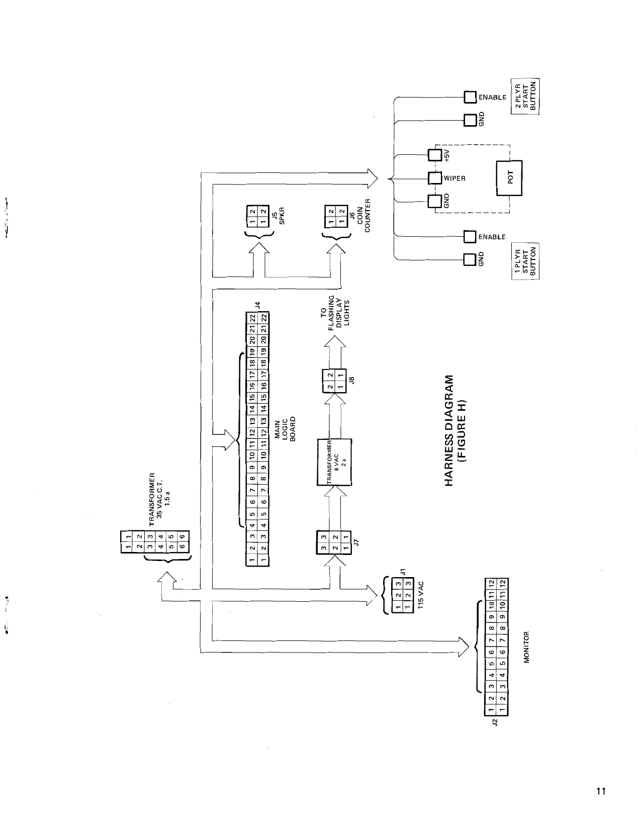
Fight@ H wy cnc a ct ee ate Rew teeta eee Ora Harness Diagram
Figured 20... eee eee eee eee Schematic Diagrams
This page carries no recoverable text. It is a drawing or a photograph. See the original scan.
(GENERAL
CIRCUS is a one or two player skill game which requires the player to bounce a jumping clown off the proper side of a springboard, and in turn, propel another clown to the top of ‘the screen where he can burst three colored rows of balloons.
The higher the clown jumps, the more balloons that can be burst and the greater the score that can be obtained. Yellow balloons in the lowest row are worth twenty points each, green balloons in the middle row are worth fifty points each, and blue balloons in the top row are worth one hundred points each. In addition, there is a point bonus for eliminating all the balloons in any row. When the clown bursts the last balloon in a row, he hangs there momentarily as appropriate ‘‘award music” is played. Then he jumps back down to the springboard and the tow of balloons is reset. An additional bonus of an extra “jump” is provided the player whenever he bursts the entire top row of blue balloons.
CIRCUS can be adjusted for 3, 5, 7, or 9 “’jumps’’ per game. As long as the clowns continue bouncing off the springboard, Points are accumulated. However, the speed of the jumping clowns increase, thereby testing the skill of the player. If the clown misses the board, he tumbles and falls, and appropriate music is played.
Multiple coinage options are available on CIRCUS, and full game instructions are displayed on the screen after the player inserts his coin. The day’s high score is flashed on the screen, and an optional “top this score” feature can be used, which awards a replay to the player who beats the day’s high score.
MONITOR DISPLAY (FIGURE A)
{l. NORMAL OPERATION
Attract Mode
When power is initially applied, the words “GAME OVER” should be flashing on the screen. Also on the screen will be “TODAY'S HIGH SCORE” followed by a score which will change with each new higher score attained throughout the day. If power is removed from the game, however, this high score will be reset to zero.
A\so displayed on the screen, at the operator’s selection, will be one of the following:
Two Player — 1 Coin or One Player — 1 Coin Two Player — 2 Coin or One Player — 2 Coin Two Player — 4 Coin
CIRCUS also has a credit counter so that one can “rack-up” a number of games in advance, as is common on mechanical pinball games.
While the game is in the ATTRACT MODE (no credits, no game in progress) the game plays automatically, as if a player were moving the springboard control. This allows the player to observe normal play of the game prior to inserting a coin.
Introduction Mode
When a coin is deposited by a player, the following message will be written on the screen:
“MOVE EMPTY SIDE OF SPRINGBOARD UNDER MAN FOR CONTINUED PLAY POP ALL BLUE BALLOONS FOR BONUS JUMP”
“CREDITS.N”
(N = A variable number representing the number of games stored up in advance by insertion of coins.)
“TOP THIS SCORE FOR CREDIT”
(N = A random variable number which, if matched or exceeded by player's score, will award one extra game credit.) Game Play
When the start button is depressed (after a coin or coins are inserted), a fanfare tune alerts the player that the game has begun.
The number of jumps (or turns) per player will be indicated in the top center of the screen at this time. This number is operator selectable to 3, 5, 7, or 9.
Upon completion of the fanfare tune, the clown will walk out on a platform, jump off toward the bottom of the screen, and the player will then have control of the springboard in order to position it horizontally underneath the clown. The empty side of the springboard must be placed under the clown so that he will bounce the other clown upward to pop balloons.
If the clown hits the side boundaries or jumping platforms, he will somersault through the air, landing upright each time, so that he may be bounced upward by the springboard.
When the clown hits the bottom boundary, he flattens out and appropriate music tells the player he has lost one turn. In a two-player game, this is the time to change players.
Awards
Color of Balloon Point Single Row Bonus
Balloon Row Value Point Value
| Yellow | 20 each | 200 |
| Green | 50 each | 500 |
| Blue | 100 each | 1000 |
SUPER BONUS awards 10,000 points.
I. SELECTABLE OPTIONS
There are four (4) switch selectable options on CIRCUS. These are controlled by a seven segment DIP switch located on the main logic board in position 14A. (See Figure D, item 8.) This switch is accessible from the front of the game through the coin door.
Following are the options and the instructions for their selection: A. Coinage Switch 4 Switch 5
| 2 Player — 1 coin | off | off |
1 Player — 1 coin
| 2 Player — 2coin | on | off |
1 Player — 2 coin
| 2 Player — 4 coin | off | on |
| Jumps (Turns) | Switch 6 | Switch 7 | D. | Bonus |
| 3 Jumps | on | on | There are two (2) bonus modes in CIRCUS. The “single |
5 Jumps on off row’’ bonus mode awards a bonus for popping all the
| 7 Jumps | off | on | balloons in any single row, The row then resets (new bal- |
| 9 Jumps | off | off | loons appear). Each row awards a different value bonus |
(see “Awards’’ below for points awarded). The “super bonus” mode awards a bonus only for popping a// the balloons on the screen.
Selection is as follows: “TOP THIS SCORE” Switch 3 Switch 2
Credit awarded for topping score off Single Row Bonus on
| Credit not awarded for topping score | on | Super Bonus | off |
AUDIO P.C. BOARD (FIGURE B)
- AUDIO P.C. BOARD 6. R29 VOLUME — POP
- MICRO PROCESSOR P.C. BOARD 7. SEVEN SEGMENT DIP SWITCH
- R63 VOLUME — MUSIC 8.R39 HIGH FREQUENCY VOLUME ADJUST- 4.R60 LOW FREQUENCY VOLUME ADUJUST- MENT — BOUNCE MENT — BOUNCE 9. R49 VOLUME — MISS
- R65 MASTER TONE 10. R47 FREQUENCY ADJUSTMENT — MISS
AUDIO ADJUSTMENTS (See Figure B)
BOUNCE — 2 pots: R60 = Low frequency volume adjustment R39 = High frequency volume adjustment POP —1pot: R29 = volume MISS — 2 pots: R47 = Frequency adjustment R49 = Volume MUSIC —1 pot: R63 = Volume MASTER TONE ~— 1 pot: R65 POWER SUPPLY ADJUSTMENTS
Power Supply Adjustment
- Connect the voltmeter leads to +5 and ground traces on the main logic board.
- Adjust the power supply “adjust potentiometer” located on the back of the monitor (Item 2 in Figure C) for +5,0VDC + .1VDC,
POWER SUPPLY ADJUSTMENTS (FIGURE C)
1.5 VOLT LOGIC SUPPLY FUSE (7 amp) 2.5 VOLT LOGIC SUPPLY ADJUSTMENT POTEN- TIOMETER
Vi. MECHANICAL ASSEMBLIES
CIRCUS Controi Panel (Figure D} Design: The CIRCUS control panel is a single metal plate 3. Lift the contro! panel up from the cabinet and with four weldedstuds for mounting. One potentio- set it on edge for bottom access. meter and two push button switches are panei 4. Check all terminal connections to switches and mounted and connected to the harness with fast potentiometer. ‘on terminals.
Procedure: To service controls: To retouch control panel finish: 1, Open front double coindoor The CIRCUS control panel is a steel panel coated
- Reaching up through the coindoor, remove the with a flat black enamel (Sherwin Wiliiams Polane wing nuts from the four welded corner studs Black). This allows the panel to be touched up that hold the control panel down. with a black spray paint.
CONTROL PANEL (FIGURE D)
1, STEEL PANEL
- ONE PLAYER SWITCH
- POTENTIOMETER
- KNOB
- CONTROL HARNESS
- TWO PLAYER SWITCH
- WELDED CORNER STUD WITH WING NUT
To Remove Monitor
. Disconnect power cord from AC outlet. . Open and remove back door. . Remove connector from monitor. Remove four bolts from monitor chassis flange mounts. . Lift monitor up and slide monitor out of the cabinet. Oona To Remove Logic Printed Circuit Board
- Disconnect power cord from AC outlet.
- Open and remove back doer.
- Clip logic PCB tie wrap at locations 5 and 13. 4, Disconnect edge connector (Item 6) from logic PCB. 5, Slide logic PCB out of rack.
MAJOR INTERNAL COMPONENTS (FIGURE E)
. MONITOR POWER SUPPLY (see Figure C detail) . LOGO LIGHT HARNESS . AUDIO POWER SUPPLY TRANSFORMER . LIGHT HARNESS POWER SUPPLY TRANS- FORMER MICROPROCESSOR TIE WRAP (1 of 2) . MICROPROCESSOR CONNECTOR
. MAIN HARNESS CONNECTOR
. AC INTERLOCK SWITCH PONS
onan
- AC POWER CORD
- AUDIO PCB
- IN LINE 5 AMP FUSE
- MICROPROCESSOR PCB
- MICROPROCESSOR TIE WRAP (2 of 2)
- MICROPROCESSOR OPTION SELECTION SWITCH LOCATION
- COIN COUNTER
Vil, TECHNICAL INFORMATION
Logic Description and Operation
CIRCUS is a microcomputer game which uses the 6502 central processor unit. (For more information on this processor, refer to MOS Technology publication #6500-10A, MCS 6500 Microcomputer Family Hardware Manual.)
This processor is unique in that it does not have a separate Input/Output structure, rather it treats all 1/O as if it were an area of memory. Memory is mapped as follows:
FFF8-FFFF Interrupt and reset vectors FO00-FFF8 Program storage (PROM) Dooo Paddle position and Interrupt reset coo0 Option Switches (Input) A000 Control Switches (Input) 8000 Clown rotation and audio control bits (Outputs) 4000-43F F Screen RAM 3000 Clown horizontal position (Controls) 2000 Clown vertical position (Controls) 1000-1F FF Program storage (PROM) 0100-01FF Stack RAM 0000-00FF Base page RAM
Page O RAM is used for storage of dynamic variables during program execution. Page 1 RAM is used by the processor as a “stack” to store return addresses and important data during subrouting execution. The program storage PROM, is where the program that controls the operation of the game is stored.
The Screen RAM consists of 1024 bytes (8-bit words) of read/ write memory which, when not being addressed by the processor, is scanned by main timing to display a matrix of 32 x 32 squares on the screen. The data stored in the screen RAM is then used to select one of 256, 8-element wide by 8-line tall images in the Screen ROM. (Note that the screen ROM is not directly addressable by the processor.) These 8 x 8 bit blocks then form images or portions of images to be displayed on the screen. (An alphanumeric character takes one block to be displayed, where an image, such as the man standing on the seesaw takes 15 blocks.) Example: to store the letter ‘“X" in the upper left-hand corner of the screen, the processor would write a 29H in location 4000 H. Then by combining the 256 different portions of images, a large combination of different images can be produced.
The same circuitry that generated Sync and scans the screen RAM is also used to generate the horizontal and vertical solid and dotted lines which form the box around the video and the diving boards. The clown is generated by two sets of counters (Horizontal and Vertical) which are used to position the clown on the screen. The outputs of the counters, along with the rotation information on the output port, are fed to the clown PROM to form the clown image. The processor controls the clown by preloading the counters to the desired position during Vertical syne.
The processor reads data from the switches by gating the data from the control or option switches onto the data bus when the appropriate address is selected.
The paddle position is an analog to digital convertor, which is read by the processor to determine paddle horizontal position.
AUDIO Description and Operation (Refer to Schematic and Block Diagram)
The audio board is powered both by +5VDC from the television tmonitor and +15VDC developed on the audio board. AC power used to develop this +15VDC is supplied by an external transformer whose purpose is to step down the 115VAC to a more usable voltage.
The audio board contains the following circuits: @ +15VDC power supply
© audio amplifier
white noise generator
bounce sound generator
pop sound generator
miss sound generator
music input eecevee video inversion driver
Following are brief descriptions of the operations of these circuits.
The +15 VDC Power Supply
The first stage of the +15VDC power supply is a full wave rectifier, which converts the input 35VAC (center- tapped) into approximately +25VDC. This latter DC voltage is not critical, however, and may vary from board to board or transformer to transformer.
The second stage is a self-contained 3-lead regulator chip (LM340T-15 or equivalent) which converts the +25VDC into +15VDC. This +15VDC source feeds most audio circuits, and the base of pass transistor Q1. This source is a relatively low current supply, so pass transistor Q1 provides a higher current +15VDC supply to the audio amplifier chips {LM380N or equivalent). Transistor Q1 is configured as an emitter follower, so the emitter voltage will “follow” the regulated +15VDC on
the base (minus approximately .7VDC, which is the normal
drop across the base-emitter junction in a silicon transistor
operating at or near saturation).
The Bounce Sound Generator
The bounce sound is triggered by a negative-going TTL pulse from the logic board. The circuit comprises two phase shift oscillators, one tuned to oscillate at a lower frequency than the other. The transistor in both oscillators (Q7, Q12) under normal conditions receives no base current and the circuit is, therefore, unable to oscillate.
Notice, for example, the oscillator in which Q12 is the active element. The base of O12 has no current path toward a positive voltage, since the anode of CR17 is pulled to ground by an open collector gate.
When signal 5 BOUNCE drives the input of the gate low, the output is allowed to swing high, forward biasing diode CR17, and creating a current path through R62 to +5VDC. This turns ‘on the oscillator and charges up capacitor C31. When signal 5 BOUNCE disappears, diode CR17 once more becomes reversebiased, shutting off the current path. In this condition, since C31 is still charged, 012 has base current for a period determined by the RC combination C31, R53.
Diodes CR11, CR18 provide output isolation, while allowing the signals to pass on to volume pots and then to the audio input buss.
The Pop Sound Generator
The Pop Sound is triggered by a negative going TTL pulse from the logic board. The Pop Sound Generator input structure is much the same as that of the Bounce Sound Generator described above, in that transistor Q6 receives no base current until the incoming signal 5 POP forward biases diode CR7, Creating a base current path toward +15VDC, and simultaneously charging capacitor C15, When the input signal is removed, diode CR7 becomes once more reverse- biased, leaving a charged up C15 to keep the circuit on for a period determined by the RC combination of C15, R24.
This circuit, however, does not oscillate. It merely amplifies the white noise previously generated, Thus, it is tike an ‘’amplifying switch’ with a small turn-off delay. A diode in the collector of Q6 provides output isolation as in the Bounce Sound Generator circuit. The Miss Sound Generator
The Miss Sound is enabled by a TTL low level input from the logic board. This generator consists of a voltage controlled oscillator {used as a tone generator) and an amplitude modulator used to “shape” the sound volume.
Under normal conditions (no input present) transistor Q11 Operates in a saturated condition, thus holding U4 pin 5 (the input to the VC}) ata relatively low voltage, and U5 pin 2 (the control input to the amplitude modulator) ata relatively high voltage. This voltage at U5 pin 2 holds the output in an “off” condition.
The duration of the input signal 5 MISS determines the duration of the Miss Sound directly. The output is fed directly to the audio input buss.
The Music Input
The music is generated entirely by the microprocessor on the logic board, out of software. The input on the audio board simply consists of an isolation and volume control network, prior to passing the signal along to the audio input buss.
The Video Inversion Driver
This circuit is for use only with cocktail table models, wherein the television display must be “turned over” in order for players on both sides of the table to see an upright picture when it is their turn to play. It consists of a single D type flip-flop used to drive a transistor (MJE182). When this transistor is turned on the collector drives toward ground, thus supplying the yoke relay with the ground it needs to energize and reverse the yoke leads in the television monitor.
The flip-flop (U2) is set (which inverts the picture) by anegative going TTL pulse from the logic board to U2 pin 10. It is reset by a negative going TTL pulse from the logic board to U2 pin 13.
DATA BUSS
SWITCH AUDIO. INPUTS , OUTPUTS ADDRESS BUSS
MICRO- PROCESSOR
CONTROL ROM
PADDLE BALL COUNTERS
SCREEN RAM
TIMING AND SYNC GENERATION VIDEO SCREEN ROM
ANALOG >
ANALOG TO DIGITAL
LOGIC BOARD BLOCK DIAGRAM (FIGURE F}
a FROM S5VAC CENTER-TAPPED
XFORMER
+ISVOC HIGH CURRENT Vee SOURCE
+15VDC r
REGULATED
POWER SUPPLY | *IBVEC
LOW CURRENT Vee SOURCE
CUSED ONLY
FOR AUDIO
POWER
NPLIFIER
AUDIO BOARD BLOCK DIAGRAM (FIGURE G) LMZBO"S)
=
WHITE NOISE
GENERATOR
+5VDC CTHROUGH Looic BOARD, FROM TV. NONITOR)
CGUPPLY ) WiGH FREQUENCY|
5S BOUNCE CENABLE === OSCILLATOR “| . _ - LOW FREQUENCY OCCiLLATOR FOP SOUND | AUDIO 5 POP | AMPLIFIER
CENABLE: GENERATOR, 5 MISS TONE-GENERATOR CENA BLE Ge caNtOLLRS OSCILLATOR) . SPKR,
AMPLITUDE NOPULATOR MUSIC. VOLUME |
CONTROL
, FMUSIC 5 GAME 5_INVERT “ENABLE NVERION : +) tom @isaeey? RESET INVERT TO TELEVISION YOKE KELAY _
BLOCK DIAGRAM ~—CIRCUS AUDIO
This page is a drawing, shown as the original scan.
“BulyzAue 0} pa}oauuod 1Ou pua Jayro — ssauiey aur YiIM ut pa|pung asim Buo| ,,9 = VNNSLNY OLVLS, HOLIMS dO¥d NIOD ODA dnnoy9 AlddNS Y3MOd HOLIMS dowd NIOD YaNV3dS Yay wads dAdiM “LOd LNo ¥4aNV3dS Lno HayVvadS +AW14Y -AW1ae OWA GE OWA GE “LOOWA SE «VNN3ILNV DILVLS HOLIMS dOHd NIOD
eer YyALNNOO NIOO ONIOD
hor oer eer ZL eer oz-or ais L-sr rer ser oer Lor
LNROD NIOO ANnN03 NIOO cor Lor zor t-sr zee le-or Oz-ofF 6L-or slvr Lior ol-or Sl-er blo elo Zor Lhe OL-or
HOLIMS LYVLS HATd Z HOLIMS LUVLS HATd L O3d\A NYNL3ay OACIA fel Ni3} 0A “LO OWA GE OWA GE OWA SE GnnoyS A1ddNS YHAMOd uaMOd YAMOd GAHOLIMS OGA B'OL daMOd YAMOd G3HOLIMS “Yds HOLINOW GNNO¥S ANID YSMOd 990A “dds HOLINOW dnnowd A1ddNS YBMOd Nunlay O3GIA O3QIA GNNOYSD ANID YSMOd
ONIOD. cor e-er YAMOd | Z-2¢ ‘Z-er Y4MOd GSHOLIMS | L-2P‘'L-Er
ber cer eer o@r vor Stor 9L-or eur our bur aur Lor eur Lor our cor vee Ler | over eer
oor sor Ler oor or ver eer aor L-or oer ser ver eer eer Ler cer Leer oL-2r oer ser Le ger ser ear cer wer eur aur Lr TWNDIS anv OL Nid TVNODIS (H aYNDIS) WVYDVIC SSANYVH
anv OL Nid
TPUP STE256
THSC
dos ego! al ipasnel [| Bsc 7 Lt Pup F SIseLK reek Rang, EE! Ez
7404_44€
NOTES LRLL400 SERIES TIL ARELOW PoweR sCHOTTHY
- STSLOMD 1. Aa = TE (see Page 1 (
427) 8E
= a ‘STL256 sy, :
iy
EX!DY INC. CIRCUS LOGIC DIAGRAM | PAGE 10F7
MASTER TIMING
o
TRE ss — 80 aD MEL MOEO.
(see pace Mt eDvID.
Aa sect ts e341 els
] q
jaree
- 70 6341
NOTES
LV ALL74005€ RIES TL ARELOW POWER SCHOTTKY i 3} & oh ae a
SWRITER
READ
|| bers | 634i) ac
EXIDY INC.
ROBOT BOWL LOGIC DIAGRAM
PAGE 20F7
VIDEO GENERATION
i NOILY YU 3N39 NVA La0¢ ove | WYHOW!O 21907 snowid “ONIAGIXE
AMLLOHDS WaMod MOT BUY TAL $3r435 ODKL TIN
SBLON
Pe i= 91 mB
- eae ae a2 20,
BK 8S & an cay oe are 7 BE oer eTaDIE ze ne wioeL = a 0! iz 7 BOs sonu[e oro toe hi preaas G #7 7 ara F Br 7
NOTES
LAL P400 SERIES TTL ARL Low POWER SCHOTTKY 2, ACL RESISTORS ARE /aw ANDIN OHMS.
3. ALL.CAPACITORS ARE IN MICO FARADS
5 R2 -29 SvorTS THM fe 388
smL256 on
(See PAGE 2}
us svour’ seiner. Te rd a m2 re] Tl rial 120 PF JUMP 4 JUMPS
DI
- 74173 Vs T ume T
Ce SHAT INO Paver ie B 7404 (see pace)
<5 START ONE PLAYER aye gre?
eau cel i_1_! roe \
wo fo (Tz Aouno. oN
b 1 BYPASS EVERY 2 PACKAGES
A = | JuMe2 z
“ tbe suoute [Tr (2€ Sunire [74 22 PINE DGE
CONNECTOR
COMP VIDEO
a) VIDEO GROUND
EXIDY. INC. CIRCUS LOGIC DIAGRAM PAGE 40F7 INPUT / OUTPUT
We) ysis Fy 4 nor a2 —2]USEn! asa
leg
VEXIDY INC. CIRCUS LOGIC DIAGRAM PAGE 5 OF 7 CENTRAL PROCESSING UNIT .
AMOWSW AINO Cv3u
£409 39Vd | WvdOVId 907 SNduYID
“ON! AGIXS
Co Wor 6m Pow +5y H 109K S10K me =
waase Ivse 5 TLcé o7
rea DE.
Tee D5:
The 1748374 |i
TB fa
ia 2.
FL OF
TE 00.
TycMP, TBOLK jrasiie| Ze 2| OE pb 19a
EX\DY INC.
PAGE 7OF 7
CIRCUS LOGIG DIAGRAM
ANALOG TO DIGITAL CONVERTER
aS it Sueur, a one +15 VOLTS
Si eu Bs silo +jovk cron) cqaassue 8 | lnm isvours wrote Fara i Al ca: 1BOONCE “ 2POP,
+5 voLrs
one. ngooe a yy MIE 182 HIGH BouNeE
NOTES. 1 ALL RESISTORS ARE Sbetirieo OTHER
- ALL CAPAC|TORS AREIN MICO FARADS ANO /SWVOC
GNLESS OTHERWISE SPECINIED OHMS AND YW UNLESS
EXIDY INC. CIRCUS SCHEMATICS
PAGE 1OF 2
AUDIO.
smIss
s0ounce R54 560k exe 033 05 05 +15 voLTS A music. +15 vouTs Lac33a0 |? us R49. TOK:
PE ae
+15 VOLTS
BR SBR
R52 criz 100K
IN4454 BF asst ys / oa 470K: ial +e “
cucH_Beonce 22K 2PoP R50, ia ceo i “—+ ay Sk e
+15 vours I R59 ark Low Bounce RS9 in
NOTES,
I ALL RESISTORS ARE IN OHMS AND ARE J/4W UNLESS
Gtaeawise see eo
2. ALLCAPACITORS ARE ARE IN MICRO FARADS ANO
‘Swibe GMLESS Orhem wise SPECIFIED
EXIDY INC,
cIRCUS
SCHEMATICS
PAGE 20F 2
AUDIO
>
NOTES