High Impact Football Kit (16-40104-101 Dec 1990)
High Impact Football (rev LA5 02/15/91) (Williams, 1990) · Manual · 63 pages · 58 sections · original scan
December 1990 16-40104-101
KIT
HIGH IMPACT FOOTBALL KIT INSTALLATION & OPERATIONS
MANUAL
- Game Operation & Adjustments
- Game Testing & Problem Diagnosis
- Parts Information
- Reference Diagrams & Schematics
WILLIAMS ELECTRONICS GAMES, INC. 3401 N. CALIFORNIA AVE. CHICAGO, IL 60618
HIGH IMPACT FOOTBALL!
Experience the earnings impact of Williams’ HIGH IMPACT FOOTBALL, and discover why sports video will never be the same again! Only HIGH IMPACT breaks new ground with LIVE ACTION football that delivers all the bonecrunching tackles, circus catches and high energy gridiron excitement.
HIGH IMPACT brings football to life with the energy and strategy of a non-stop highlight film. The reason is Williams’ own exclusive digitized graphics technology for on-screen football action that’s so real players will feel like suiting up!
With 15 Pro-Action teams to choose from, HIGH IMPACT packs scoring power and continuous buy-in profit punch for 1 to 4 players. There’s easy-to-use single “Move” joystick and “Action” button Superstar™ Controls, with over 40 authentic Offensive plays and Defensive formations to choose from.
This is the single football game you've been waiting for! Players will test their skills to master long-range Bombs, Double Reverses, Half-back Options, Nickel Defense, Zone Coverage, Stunts, Red-Dog Blitz and so much more.
HIGH IMPACT brings you all the action on and off the field - the cheerleaders, the coaches, the outrageous banter of Manic Max™ the deranged play-byplay commentator, the hot dog antics of the players and the cheers and jeers of the fans led by Joe Six-Pack™,
Game Rules:
1 Player on a team: You are Quarterback and Defensive Captain. 2 Players on a team: Players 2 & 3 are Quarterbacks. Players 1 & 4 are Defensive Captains. START/BUYIN: Insert coin(s) and hit START button for each coin.
OFFENSE PASS: Point Joystick to receiver, hit Action button. Handoff: Point Joystick to halfback, hit Action button. Spin Move: Hit Action button & move Joystick up or down. Jump Move: Hit Action button & move Joystick right or left. Kick: Tap Action button rapidly to increase distance.
DEFENSE Select Player To Control: Hit Action button before hike. Turbo Speed: Hold down Action button for Awesome Speed Burst. Killer Tackle: Hit Action button. Interception: Hit Action button for leaping catch. Block Kick: Hit Action button.
Table of Content
Section 1: Kit Installation, Operation & Troubleshooting Safoty............ Conversion Instructions
Template for 2 & 4 player Control Panel Conversions. Installing PC Boards into a JAMMA Game Cabinet. Installing PC Boards into a NON-JAMMA Game Cabinet Installing the Volume Control. Game Features Starting-up. Player Cont Typical 2 & 4 Player Control Panel Layouts. Control Panel Decal Template...........0:.04. Game Operation- Contro! Switche: Game Adjustment & Diag! Starting up... Main Test Men Diagnostic Test: Switch Test. DIP Switch Test & Cha CPU & Sound Tests...... Monitor Patterns & Burn-in Tests. Coin Bookkeeping. Game Audits...... Game Adjustment: Standard Pricing Chart. Custom Pricing. Utilitie: Troubleshooting. BUbunhiu CONGDAAOH
Section 2: Parts Audio Board Layout... CPU Board Layout.
Section 3: Diagrams & Schematics Audio Board Schematic. CPU Schematic JAMMA Chart. High Impact Kit Wiring Diagram High Impact Kit Interboard Wiring Diagram. Coin Switch & Meter Wiring Diagram. Control Panel Template Diagram(s).
COPYRIGHT© 1990 WILLIAMS ELECTRONICS GAMES, INC. ALL RIGHTS RESERVED
NOTES:
HIGH IMPACT FOOTBALL KIT
SECTION one
Installation, Operation & Troubleshooting
Safety Notices
The following safety hints apply to all kit operators and service personnel. Specific warnings and cautions will be found throughout this manual where they apply. We recommend that you read this page, and also all of Section 1, before preparing your kit for play.
NOTICE: SALVAGED PARTS Parts salvaged from old games are required to. cornplete your kit. These salvaged parts must operate perfectly: otherwise, the converted game cannot perform properly or safely. Always repair Circuit board matifunctions and cabinet damage before conversion is attempted.
NOTICE: POWER SUPPLY Be sure the power supply from your old game is capable of +5V dc at 5A ,-5V dc at 1A and +12V at 1A. These operating voltages are necessary for your kit. Your power supply must be FCC approved.
NOTICE: MONITOR This kit isnot intended for use with X-Y monitors. Suitable monitors have horizontally mounted CRTs and raster electronics with inputs for red, green and blue video, as weil as composite Negative syne input,
; NOTICE: COIN MECHANISM Be sure to clean and lubricate your old coin mechanisms. Servicing them is crucial to your game's eaming potential and operation.
NOTICE: COIN METERS Coin meters are not provided with this kit. Wiring information is provided as a convenience to the operator.
NOTICE: SERVICING, INSTALLING Ajwvays tum your game OFF and unplug it before attempting to service or install your kit.
PROPERLY ATTACH ALt CONNECTORS. Be sure that the connectors on each printed circuit board (PCB) are properly connected. If they do not slip on easily, do not force them. A reversed connector may damage your kit and void the warranty. All connectors are keyed to fit specific pins on each board.
Conversion Procedure
Inspection Unpack the materials from the carton and inspect for obvious signs of damage. Use this checklist to be sure your kit Is complete.
() 31-1612-40104 Control Panel Overlay Q 31-1613-40104 Marquee () 31-1616-40104 Decal Cabinet Side Q 31-1617-40104 Decal Control Panel () 4308-01123-20B Cairage Bolt 8-32x1-1/4 () 5795-10937-18 Ribbon Cable () Assorted Hardware Part No. ttem Quantity
| () A-8550-1 | Pot & Bracket Assembly | 1 |
| 0) C-13234-40004 | CPU Y-unit | 1 |
| () C-9214-1 | Button Assy-Blue | 2 |
| 0) C-9214-4 | Button Assy Red | 2 |
| Q) C-9214-5 | Button Assy-White | 4 |
| () A-1397 1-40004 | Audio Board Assy | 1 |
| () H-12758 | Audio Board Jumper Cable | 1 |
| () H-13257 | Sound Pwr/ Spker Cable | 1 |
| () H-13724 | Player 3 & 4 Cable | 1 |
| () H-8865 | Volumn Control Cable 18" | 1 |
| () H-8866 | Volumn Control Cable Assy | 1 |
| () 03-8250 | Control Panel Cover | ] |
| Q) 16-40104-101 | Manual | 1 |
| () 16-9192 | Template Control Panel | 1 |
() 16-9192-1 Template Control Panel P21 () 16-9192-2 Template Control Panel P31
| () 16-9192-3 | Template ControlPanelP4 | 1 |
| () 20-9222 | Painut 5/8 | 8 |
| () 20-9319-1 | 8-way Joystick- Red | 2 |
| ():20-9319-9 | 8-way Joystick- Blue | 2 |
| () 20-9457 | Button Holder w/Switch | 8 |
Recommended Tools and Supplies Q black semi-gloss paint Q electric drill Q electric screwdriver Q grease pencil or marker Q hex driver ( 180 grit sandpaper or electric sander Q pliers © razor knife ( soldering iron and solder ( wire cutters () black electrical tape ( quick-hardening wood putty
Cabinet Modifications
- Fillin gouges with a good quick-hardening wood putty. Sand cabinet and wipe ft clean.
- Repaint the cabinet with black semi-gloss paint (Games wood grain sides: remove the old decals and clean the glue residue from the old decal before painting). Allow paint to dry completely.
3, Pencil aline roughly at the top of the old graphic. Lightly moisten the cabinet with soapy water. Apply the decal starting at the top and working down. After the decal Is in place, use a squeegee and smooth the decal down, taking care to squeeze out the air bubbles. If you miss an alr bubble, pop it with a razor blade or a pin and bumish it down. Allow 12 hours forthe adhesive in the decals to set. Remove masking.
4, Check the HIGH IMPACT FOOTBALL Kit for an FCC sticker and apply it over the existing sticker on the cabinet.
When Williams Electronics ships a game, it is in compli ance with FCC regulations. The FCC sticker is proof. If the sticker is missing or damaged, legal repercussions to the owner or distributor of the game may result. If your game kit does not contain an FCC sticker, call Williams Electronics immediately.
- Applythe Instructions (Card orDecals) tothe CRT viewing glass.
Control Panel Modifications
- Remove the Control panel buttons and joysticks and remove the old vinyl covering.
- Place thetemplate onthe control paneland use it tohelp you design your control panel. You will need to use the Mounting Template for each player you Intend to install.
- Drill holes as needed for the joysticks and buttons. Plug previous ho'es with wood blocks, putty, cardboard or epoxy. File the new holes smooth.
- Carefully remove the backing on the vinyl control pane! overlay. Place the overlay on top of the control panel. Prevent air bubbles from getting under the vinyl overlay.
1-5
4- PLAYER CONVERSION KIT
Barre Fhales 1 AL ro 25 aa $e0biemmes fra 9 gare, came eens eel Beg Err: Beare 689 os
TEMPLATE CONTROLS pene m USD OW 40/08 Hr Paras
= i J eg— | BR eTeRY |
2 - PLAYER CONVERSION KIT
- a) After the overlay is on securely , use a razor knife to cut holes for the buttons and joysticks.
- Position the stickers around the appropriate button locations. Refer to the Typical Control Panel Layout diagrams on the next pages for suggested button and Joystick locations. Cc) Peel the backing from the adhesive on the clear protective overlay. Position the overlay so that it covers the stickers and press it into place. Use a razor knife to cut holes for the joystick and buttons.
- To mount the pushbuttons and button-holder/switch to the control panel, push the threaded end of the pushbutton through the control panel from the top so that the threads extend through the back of the control panel. Then, take the white plastic button holder/ switch and place It over the pushbutton threads so. that the threads extend through the hole in the holder. The biade switch must point toward the back of the cabinet and face you. Secure Into place with a painut. Repeat for all of the pushbutton switches.
- To mount the joystick assembly to the control panel first Position the switch assembly so that the square base Is against the back of the control panel and the hole in the base lines up with the joystick hole in the control panel. Secure the switch assembly to the control panel. Be sure that the blade switch with the red wire (move up) faces the monitor when the control panel is closed. Remove the "E"-ring , white plastic spacer and spring from the joystick shaft. Slip the black plastic washer around the joystick shaft so the rough side faces the handle. Push the shaft through the Joystick base from the front of the control panel. After the shaft is through the base, replace the spring, spacer and "E"-ring.
1-6
Properly insulate any unused wires within the JAMMA Cable. Installing the PC Boards and Wiring intoa JAMMA Game Cabinet
- Disconnect and remove the existing video board in the JAMMA Game Cabinet.
- Mount the HIGH IMPACT FOOTBALL KIT video board inside the JAMMA Game Cabinet where the old video board was located
. If you choose to use the JAMMA Cable provided with the kit, unsolder your old JAMMA cable from the speaker, power supply, control panel switches (which may already be disconnected) and coin door. Remove the cable from the game. If you are not going to use the JAMMA Cable provided with the kit, check the JAMMA Cable Connector Chart to be sure your cable is compatible. Leave your power supply chassis as is.
- Connect the JAMMA Cable to J1 on the HIGH IMPACT FOOTBALL KIT video board. Using the JAMMA Cable Con nector Charl for reference, solder the correct JAMMA. Cable wires to the speaker, power supply. control panel switches and coin door. Plug the player 1 & 2 JAMMA connectors into their joystick cable connectors.
- a) Fora(4) player conversion, wire the player 3/4 cable from players 3 & 4 contro! panel joysticks & buttons to connectors 3P & 4P on the CPU Board.
- Fora (2) player conversion, ignore above (a) and procede.
- Connect the player 3 & 4 joystick harness from the CPU board to the joysticks. The 3rd player connector has red wires and is connected from J4 on the CPU board to the player 3 joystick. The 4th player connector has blue wires andis connected from J120n the CPU boardto the player 4 joystick.
7, J6,J7, and J9 on the CPU board are not used.
- Place the FBI Warnng Label on the inside of the cabinet next to the PC boards. Be sure the label is completely visible.
Installing the PC Boards and Wiring into a NON- JAMMA Game Cabinet
1, Disconnect and remove the existing video board in the JAMMA Game Cabinet.
- Mount the HIGH IMPACT FOOTBALL KIT video board inside the JAMMA Game Cabinet where the oid video board was located. Mount the sound board next to the CPU board using the stand-offs and screws provided.
- Leaving several inches of wire, cut the wires at the coin door, control panel switches (which may already be dis connected) speaker and power supply.
4, Connect the JAMMA Cable to J1 on the HIGH IMPACT FOOTBALL KIT video board. Follow the JAMMA Cabie Connector Chart and splice the wires of the JAMMA Cable to the existing wires forthe coin door, power supply, speaker andcontrol panel. Be sure all of the spliced wires are well insulated with black electrical tape.
- a) Fora (4) player conversion, wire the player 3/4 cable from players 3 & 4 control panel joysticks & buttons to connectors 3P & 4P on the CPU Board.
- For a (2) player conversion, ignore above (a) and procede.
- Connect the player 3 & 4 joystick harness from ihe CPU board to the joysticks. The 3rd player connector has red wires and is connected from J4 on the CPU board to the player 3 joystick. The 4th player connector has blue wires and Is connected from J12 on the CPU board to the player A joystick.
- J6, J7, and J9 on the CPU board are not used.
- Place the FBI Warnng Label on the inside of the cabinet next to the PC boards. Be sure the label is completely visible. The Ribbon Cable may need to be twisted in order to connect it properly.
Be sure all spliced wires are well insulated with black electrical tape.
Properly insulate any unused wires within the JAMMA Cable.
installing the Volume Control
Mount the volumn control, using screws provided, where itis easily accessible. On top of the cash box, or on the wail near sound board are two possible locations.
The volume control cable attaches the volume control to the sound board at connector J2. When viewed with the white plastic knob facing you, the shield wire should be soldered to the right lug. the red wire should be soldered to the middle lug, andthe biack wire should be soldered to the left lug. Refer to Volume Control Diagram.
Volume Control Wiring Diagram Red
Black Shield
Game Features
Starting Up
Switch on powertothe game. A “rug" pattern appears on the crt screen. When the ‘rug" pattern ends, the screen shows CHECKING SCRATCH RAMS, and then CHECKING ROMS. The next screen shows HIGH IMPACT FOOTBALL REVISION LEVEL, CMOS TEST OK and the COIN SETTING. The game then moves to the attract mode. After the proper coinage has been inserted, the game exits the attract mode and enters the play mode.
Player Controls
& Each Start button allows (1 to 4) players to begin play or continue play.
@ 1 Action button per player.
f 1 Joystick (Move) per player.
& See following page for detailed con trol panel conversions (2 & 4 player), and a template layout for (2 & 4 player) control panel decal sugges-
tions. 4 Player
HIGH IMPACT FOOTBALL KIT IS A1TO 4 PLAYER GAME.
HIGH IMPACT FOOTBALL will operate in the Test Mode, when the Test Switch (on the cash box cover) is closed or DIP Switch Bank #2 Switch #6 is closed.
When an error is detected during Start-up Tests, game start-up does not progress, and an error message appears on the screen.
HIGH IMPACT FOOTBALL Control Panel
O oO
or
Move © e)
1 Action © 1 Start 2Start 3 Start
oO Move 2 Action © 3 Action Move (o) 4Start
4 Action ‘e)
Move
1-11
Suggested Control Panel
Layout for Four Player Conversion
Layout for Two Player Conversion a ©
1 Start
Move
(10) ™~4 (2) ©
Action
Match (#) with decal number on previous page.
m © (8)
2 Start
, ©) Move 2 Aeon (11) ‘ew ©
3 Start
New
©) O ©) 4 Action \ (13)
(5) 3 Action N (12) ZA
Match (#) with decal number on previous page.
(16) ae)
(19) \O Move 1 Action O 2 Start (15) v YY
(17) ra () 2 Action ~ (20)
BI 8 PRE o JC Rj»CB) woes
- Four Player Instruction Card
- Player One Defensive Captain (Red)
- Player Two Quarterback (Red)
- Player Three Quarterback (Blue)
- Player Four Defensive Captain (Blue)
- Start Player One (Red)
- Start Player Two (Red)
- Start Player Three (Blue)
- Start Player Four (Blue)
- Action (Red)
- Action (Red)
- Action (Blue)
- Action (Blue) 2 PLAYER DECAL SET:
- Player One Quarterback (Red)
- Player Two Quarterback (Blue)
- Start Player One (Red)
- Start Player Two (Blue)
- Two Player Instruction Card
- Action (Red)
- Action (Blue)
Game Operation
HIGH IMPACT FOOTBALL Is a one to four player video game with acolormonitor. Fromthe player's perspective, the game hastwo modes of operation: Ready-to-Play and Play. Forthe owner/operator, the game has an additional mode of operation called Game Diagnostics and Adjustments.
Control Switches
- «The COIN DOOR SLAM TILT SWITCH detects any forceful vibrations against the Coin Door. This eliminates pounding for free games. (OPTIONAL SWITCH)
fj The VOLUME CONTROL allows increasing or decreasing the volume level of the game music and speech. For greater profits, set your game's volume level at its maximum.
Ba The TEST/DIAGNOSTICS SWITCH allows you to enter into the game's Diagnostic mode. Move the Test Switch to enter the Diagnostics Mode. To exit this mode, select EXIT TO GAME OVER from the Diagnostics main menu. (OPTIONAL SWITCH)
- The SERVICE CREDIT SWITCH is a special feature switch that allots credit without affecting the game's bookkeeping total. (OPTIONAL SWITCH)
Stam Tilt Switch
Volume Control
Test/Diagnostics Switch
Control Switch Locations
1-13
Game Audits, Adjustments & Diagnostics Operation
All HIGH IMPACT FOOTBALL Game Audits, Adjustments, and Diagnostics are options of the Main Test Menu. Each option, inturn, has its own menu listing several choices that you may act upon as desired.
Move the Test Switch (on the cashbox lid panel) to activate the HIGH IMPACT FOOTBALL Adjustments and Diagnostics. Main Test Menu (shown below) then appears. Game adjustments, bookkeeping, and diagnostics are allaccessible from this menu.
Move any joystick up or down to cycle through the menu options. Notice that the options are highlighted in sequence. Selecting a desired option requires it to be highlighted. Toactivate the selected option, press any button.
The Main Test Menu lists six options.
SELECT WITH ANY STICK ACTIVATE WITH ANY BUTTON
y
DIAGNOSTIC TESTS COIN BOOKKEEPING
GAME AUDITS. GAME ADJUSTMENT .
UTILITIES
EXITTO GAME OVER
Main Test Menu
1-14
DIAGNOSTIC TESTS To enter the Diagnostic Tests from the Main Test Menu, move any joystick to select (highlight) the Diagnostic Test option, and press any button to activate the option. The Diagnostic Tests Menu lists seven options.
SELECT WITH ANY STICK _
ACTIVATE WITH ANY BUTTON
SWITCH TEST
DIP SWITCH TEST SOUND BOARD TEST
CPU BOARD TEST.
"MONITOR PATTERNS BURN-INTEST
__ RETURN TO MAIN MENU _)
Diagnostic Test Menu
Switch Test The Switch Test allows the operator to test the switches on the control panel and the coin door.
Select the Switch Test by using any joystick to highlight the Switch Test option; then, press any button to activate it. The top of the screen shows a layout of the control panel and the bottom of the screen lists the coin door switches. Pressing a switchcausesthe corresponding switchlocation onthe screen to light. Release the switch and the screen returns to normal.
Select the RETURN TO MAIN MENU option to return to the Diagnostic Test Menu.
DIP Switch Test The DIP Switch Test allows the operator to check the position of the two 8-position DIP switches on the CPU Board. The operator can also change the setting of each position of each DIP switch during this mode. Select the DIP Switch Test by moving any joystick to highlight the DIP Switch Test option; then, press any control panel button to activate the test. The screen displays a layout of the DIP switches and their current settings. To change the setting of either DIP switch, press the switch position (SW1 - SW8) to the desired setting (ON from OFF, or vice versa). Check the screen to verify that the switch now shows the setting desired.
rte any control panel button to retum to the Diagnostic Test
lenu.
DIP Switch 1 Settings Table
es ES 4 Player 2 Player
DIP Switch Coinage Coin Settings Ger 1 Fr Ger2 Fr2 Ger3 Fr3. Ger 4 Fr4 GerECA FrECA NU NU NU NU Free Play Free Play
One Counter Two Counters
( NOTE )
AS soon as a faulty chip is detected, the CPU Test stops. The remaining chips are not tested. CPU Board Test The CPU Board Test (much like the Start-up Test) allows the operator to check the RAMs and ROMs.
Select the CPU Board Test with any stick; then, press any button to activate the automatic test of the CPU Board's RAMs and ROMs. When this test is activated, a ‘rug™ pattern appears onthe screen, The screen then changestoshowthe layout of the RAMs, and ROMs on the CPU. Any chip that is shown as black with a white outline is part of the CPU and should turn either red or green during the CPU Test. Any chip that is shown as gray with a white outline is not installed in the game. During the test, chips are good, ifthey turn green; they are faulty, if they turn red.
Sound Board Test The Sound Test allows listening to some of the sounds that HIGH IMPACT FOOTBALL Is capable of producing. This test also emits a tone for each fault that is detected.
Select the Sound Board Test with any stick; then, press any button to activate the test. The screen displays two test options:
GENERAL TEST analyzes the sound circuitry. A successful test causes a single “tone” to sound. Detection of a fault causes a series of tones to sound. When no tone sounds, this also indicates a Sound Board problem.
PLAY SOUNDS tests synthesized & digitized sounds from the Sound Board. Advance to the next sound by moving any stick, and press any button to return to the Sound Test Menu.
~ GENERAL TEST
"BACK TO DIAGNOSTICS MENU
_ RETURN TO MAIN MENU
Sound Test Menu
Monitor Patterns The Monitor Patterns Test provides a menu for testing the monitor.
Move any stick fo select a test; press any bution to activate the test. (GelecT WH ANY stick \ (ACTIVATE WITH ANY BUTTON >) (exo sc SCREEN
GREEN SCREEN
BLUE SCREEN COLOR BARS |
CROSSHATCH PATTERNS
BACK TO oo MENU RETURN i MAIN MENU
Monitor Pattem Menu
The RED, GREEN, and BLUE SCREEN tests fill the screen with either red, green or blue. Tne COLOR BARS test fills the screen with several gradiated colors to help with red, green and, blue level adjustments. Each color should appear sharp and clear. The CROSSHATCH PATTERNS test fills the screen with a grid and d series of dots. The grid and the dots should be clear. The dots should appear round.
'f any of the Monitor Pattern Tests shows a need for adjustment, use the proper white knobs on the Monitor Board,
Select Monitor Patterns Menu with any stick, and press any button to activate. From this menu, select RETURN TO MAIN MENU with any stick and activate with any button.
Bum-in Test The Butn-in Test continually repeats the CPU Board Test. Move any any stick to select the Burn-in Test; then, press any button to activate the test. When the Burn-in Test detects an error, the test stops and displays an error message on the screen. The fourth page of the Audit Table specifies the number of Burn-in cycles successfully completed. Use this test to find intermittent CPU problems.
To exit this test. switch off the game; then, switch it on again.
1-18
COIN BOOKKEEPING To enter the Coin Bookkeeping from the Main Test Menu, move any stick to select the Coin Bookkeeping option: then, press any button to activate ft. The Coin Bookkeeping Table records the coinbox totals and game play counters. The left side of the table names the bookkeeping item: the right side shows the number of coins, credits, or plays for each item.
( THRRD SLOT CONS ° ‘GHT SLOT COINs .
_ FOURTH Si stor CONs : _ SERVICE CREDITS ‘PAID CREDIT | TOTAL PLAYS: oo / _UAYS UNL HH SCORE REST. 5000 iy
| (MORE DETAILED DATA _— | RETURN TO MAIN MENU Coin Bookkeeping Table To exit Coin Bookkeeping, move any stick to select RETURN TO MAIN MENU; then, press any button to activate it.
fiGit sior CoINs ‘THIRD SLOT COINS : ~ Four SLOTCOINS- TOTAL COLLECTIONS. Q CLEAR COIN METERS __RETURN TO MAIN MENU _ Total Collection Table
GAME AUDITS To enter Game Audits from the Main Test Menu, move any stick to select the Game Audits option; then, press any button to activate it. To advance to the next (or return to the previous) page of the Game Audit Table, move any Joystick to select either "Next Audit Page", or "Previous Audit Page"; then, press any control panel button to change the page.
The Game Audits Table records the game play statistics. The left side of the table names the Audit item; the right side shows the amount of play. ( TOTAL GAME UPTIME >) TOTAL PLAY TIME
TIME 1 PLAYER ONLY.
: TIME 2 PLAYER SIMULTANEOUS
TIME 3 PLAYER SIMULTANEOUS
__ TIME 4 PLAYER SIMULTANEOUS Oo oc 8&8 8S & 2
NEXT AUDIT PAGE RETURN TO MAIN MENU | - —/y PAGE 1 OF AUDIT TABLE
{ TOTAL PLAYS : )
1 PLAYER GAME STARTS
2 PLAYER GAME STARTS
3 PLAYER GAME STARTS
4 PLAYER GAME STARTS
CONTINUES OFERED
CONTINUES TAKEN
CONTINUES REFUSED o G@ © 8 &© oO 82 59 Co
GAMES PLAYED TO COMPLETION NEXT AUDIT PAGE PREVIOUS AUDIT PAGE RETURN TO MAIN MENU
PAGE 2 OF AUDIT TABLE yy
1-20
GAME AUDITS CONTINUED ( ~LEFTTEAM TOUCHDOWNS. 7) RIGHT TEAM TOUCHDOWNS —
- PASSES ATTEMPTED. 0 : PASSES COMPLETED. oO oO sames HUMAN FIELD GOAL AT : HUMAN FIELD GOAL COMPLETONS 0 HUMAN BRA Poin ATTEMPTS 0 A POINT COMPLETIONS | [NEXTAUDITPAGE | PREVIOUS AUDITPAGE | [LRETURNTOMAINMENU | HUMAN)
(= PAGE 3 OF AUDIT TABLE
HUMAN INTERCEPTIONS DRONE INTERCEPTIONS ae UR CYCLES SUCCESSFULLY COMPLETED.
PREVIOUS AUDIT PAGE J
RETURN TO MA MAIN MENU,
PAGE 4 OF AUDIT TABLE To exit the Game Audit Table , move any stick to select RETURN TO MAIN MENU; then, press any button to activate it.
1-21
GAME ADJUSTMENTS Move anyjoystickto select the Game Adjustment option on the Main Test Menu; then, press any button to activate it.
The Game Adjustments option allows the owner/operator to change the Game Pricing and Game Difficulty.
The Game Adjustment Menu offers several choices. Each choice has its own menu. Move the left joystick to select your choice to be changed from the Game Adjustments Menu; then, move right joystick to activate that choice. On the next menu screen, move the left joystick to select the item you wish to modify; then, move the tight to activate that item. If the activated item only provides a setting choice, move any joystickto change the current setting to the desired value; then, press any button to lock inthe desired value. Moving the joystick up increases the setting value shown on the screen. Moving the joystick down causes the value shown on the screen to decrease.
SELECT WITH ANY STICK
ACTIVATE WITH ANY BUTTON
RETURN TO MAIN MENU lote, Game Adjustments So oe are explained in more CREDITTIMER = =———s||_ | detail on the following ATTRACT MODE SOUNDS page.
GAME CLOCK SPEED
STANDARD PRICING _
CUSTOM PRICING
GAME DIFFICULTY
FREE PLAY
RETURN TO MAIN MENU
Game Adjustment Menu
1-22
Credit Timer Controls the speed of the player credit timer. The settings for the adjustment are:
- Slow
- Medium (factory)
- Fast
Attract Mode Sounds Determines whether the game will make sounds in the attract mode. The settings for the adjustment are:
- Yes (factory) -No
Game Clock Speed
Allows the operator to adjutst the speed at which the game Clock will countdown, The settings for the adjustment are:
- Slow
- Medium (factory) ~ Fast
Standard Pricing
Standard Pricing allows the operator to choose any of the "Standard" selections for the Standard Pricing Table.
Custom Pricing
Custom Pricing allows the operator to install pricing other than that of the Standard Pricing Table. Custom Pricing also allows the operator to select the maximum amount of credits per game, the amount of credits required to start a game, and the amount or credits required to continue a game. This option is being adjusted from the Dip Switch Settings.
Game Difficulty
Game Difficulty allows the operator to select the difficulty level of the game. The settings for the adjustment are:
- Easy
- Medium (factory)
- Hard
Free Play
This option allows the operator to select free play. The-settings for the adjustment are:
- No (factory)
- Yes
1-23
HIGH IMPACT ae Standard Pricing Table
Credit/Coin CHUTE USA 1 1/25¢ USA 2 1/50¢ USA3 1/50¢, 3/$1.00 USA4 1/50¢, 4/$1.00 USA ECA 1/25¢, 4/$1.00
German 1 1/1 DM, 6/5 DM German 2 1/1 DM, 7/5 DM German 3 1/1 DM, 8/5 DM German 4 1/1 DM, 5/5 DM German ECA] 1/1 DM, 2/2 DM, 6/5 DM
France 1 2/5 F, 5/10 F France 2 2/5 F, 4/10 F France 3 1/5 F, 3/10 F France 4 1/5 F, 2/10 F France ECA | 1/3X1F, 2/5F, 5/2X5F a5 5F
UK1 1/20 P, 3/50 P 50P UK ECA 1/30 P, 2/50 P, 4/21.00 é. _ 50P
If option desired is not shown above, use custom pricing .
1-24
GAME ADJUSTMENTS CONTINUED CUSTOM PRICING
(1)
@)
(3)
(4)
6)
©)
(8) ce “SELECT WITH ANY STICK a ACTIVATE WITH ANY. BUTTON
Coins inserted accumulate units. This adjustment specifies the number of units given for each coin in the fourth chute (see “units/credit").
This is the number of coin units required to buy one credit.
One bonus credit is awarded after this many coin units have accumulated.
No credits will be awarded until this many coin units have accumulated.
Each player needs this many credits to begin a game.
Each player needs this many credits to continue a game.
The detailed bookkeeping screen shows total collections based on this many coins per dollar. (Set to zero to disable the display of money totals)
This is the limit for the credits counter. Additional coins inserted will be lost. (factory setting: 30)
1-25
UTILITIES Onthe MainTest Menu, move any joystickto select the Utilities option; then, press any control panel button to activate it.
The Utilities option allows the owner/operator to clear the game's bookkeeping memory and fo install a custom message.
‘SELECT WITH ANY STICK - _ ACTIVATE WITH ANY BUTTON &
(SET OPERATOR MESSAGE >)
CLEARCREDIIS
CLEAR COIN COUNTERS RESETHIGH SCORE
CLEAR GAME AUDITS |
DEFAULT ADJUSTMENTS
\ RETURN TO MAIN MENU y Utilities Menu
Move any joystick to select an item from the Utilities Menu; then, press any control panel button to activate that item. After an item hasbeen activated, you are given the option of resetting the item or not. For example;
CLEAR CREDITS ARE YOU SURE ?
YES NO
Move any joystick to choose YES or NO; then. press any control panel buttontolockin your choice andtoretur to the Utilities Menu.
To exit Utilities, move any joystick to select RETURN TO MAIN MENU; then, press any control panel button to activate It.
1-26
Troubleshooting
Problem
NO PICTURE OR DISTORTED PICTURE.
TURN GAME ON & NOTHING HAPPENS
NO SOUND
NO GENERAL ILLUMINATION
MOVE JOYSTICK, BUT PLAYER DOES NOT MOVE
PRESS START or ACTION BUTTON AND NOTHING HAPPENS
NO CREDIT GIVEN WHEN COINS ARE INSERTED
TOO MANY CREDITS FOR NUMBER OF COINS INSERTED
GAME STAYS IN THE TEST MODE. Possible Solution
Check for fautty video board or monitor, Check for disconnected video signal cable.
Check line fuse. Check for +5V de at pins C, D, 3, and 4 of the JAMMA Connector.
Check the speaker and speaker connection to pins Land 10 on JAMMA Connector. Check volume control setting. Check for +12V de at pins F and 6 on the JAMMA Connector. Check interboard wiring from CPU Board to Sound Board.
Check the 1 A., S-B fuse on the the bottom of the cabinet below the coin box.
Check for open wires between Joystick and CPU Board. Check for contamination on joystick switch contacts and CPU Board pins. Check for proper ground.
Check for open wires between button and CPU Board. Check for contamination on CPU Board pins or button switch blade contacts.” Check for proper ground.
Check DIP switch coin setting. Check for contamination on coin switch contacts. Check for an open wire between Coin Switch 1 and pin 16 on JAMMA Connector or Coin Switch 2 and pin T of JAMMA Connector.
Check Game Pricing setting. Check for a short between pins T & 160n JAMMA Connector.
Check that the Test Switch (if you have Installed one) and the Test Switch (Position 8) on DIP Switch 2 are set to OFF.
1-27
NOTES:
HIGH IMPACT FOOTBALL KIT
SECTION Two
PARTS INFORMATION
[= [_wanmoeme | SP [NOR tari [24725 A [seep 24 Pia nam * 2" 20eTT INEO. “456 SEE SHEET 2, [9-17-90 AUDIO BOARD ASSEMBLY A-13971-40004
_ltem___ Part Number __ Designation ___ Description
| 1 | 20-9229 | Thermal Compound | ||
| 2 | -4006-01113-06 | 96-32 x 3/8 P-PH-S | ||
| 3 | 4406-01128-00 | 6-92 Hex Nut | ||
| 5 | §010-08772-00 | RIB | RES, 15K 1/4 W 5% | |
| 6 | 5010-08824-00 | R32 | RES, 43K 1/4 W 5% | |
| 7 | 5010-08846-00 | R34 | RES, 220K 1/4 W 5% | |
| 8 | 5010-08983-00 | R7,R8, RO | RES. 3.3K 1/4 W 5% | |
| ® | 9 | 5010-08001-00 | Al, R4, RS, At1, At2, R25 - R28, | RES, 4.7K 1/4 W 5% |
R33, R36, A37, R49, RSO
| FOR A 74 PIN PART, MOUNT FART JUSTIFIED | ALL | 10 | '5010-08908-00 | Re, RB | RES. 2.2K 14 W5% |
| THE WAY | TO THE BOTTOM OF THIS LOCATION. | " | 5010-00084-00 | IT, P22 - R24, ROM | ES. 10K 1/4 W 5% |
| 12 | 5010-00161-00 | 35, FAS | RES. 2.20 V4W5% | ||
| 14 | §010-09162-00 | R39 | RES. 100K 1/4 W 5% | ||
| 8 | 5010-00179.00 | RIO | RES. 9.9M 1/4 W 5% | ||
| 16 | 5010-00181-00 | Raa, Raa | RES. 10 172W5% | ||
| 7 | '5010-09210-00 | 38 | RES. 8.2K 1/4 W 5% | ||
| 18 | 5010-09324-00 | RG, R19, R20, R21 | RES. 27K 1/4 W 5% | ||
| 19 | §010-08331-00 | RIG | RES, 13K 1/4 W 5% | ||
| 20 | 5010-08333-00 | R29 | RES. 180K 1/4 W 5% | ||
| 2 | 5010-08342-00 | R20 | RES. 36K 1/4 W 8% | ||
| 22 | 6010-08358-00 | R41, R42 | RES. 1K 1/4 W 5% | ||
| 23 | 5010-00061-00 | 49, FB, RAT | RES. 2200 1/2 W5% | ||
| 24 | 5010-10258-00 | ‘R40 | RES. 1M 1/4W 5% | ||
| 25 | 5010-10885-00 | ‘R14, AIS | RES. 20K 1/4 W 5% | ||
| 26 | 5013-00427-00 | pry | RES. 4.99K 1/4 W 5% | ||
| 27 | 5040-09343-00 | C1, C3, C4, C8, C17 | CAP. 10M 20V 4/- 20% | ||
| 28 | 5040-08065-00 | cw | CAP. 1M 63V +50% -10% | ||
| 20 | §040-09776-00 | C26, C30 | CAP. 470M 16V +50% -10% | ||
| 0 | 5040-10874-00 | C12, C19, C24 | CAP, 100M 35 | ||
| at | 5040-12006-00 | C29, C32 | CAP. 1000M 16V 20% RD. | ||
| 32 | 5041-09243-00 | C25, C28 | CAP. 10M 10V +/-10% | ||
| 3 | 5043-08980-00 | 5, B(17) | CAP. .01M SOV +80% -20% | ||
| 24 | 5049-08006-00 | 31,033 | CAP. 1M SOV 4/-20% | ||
| 35 | 5043.00065-00 | 613,014, 018 | CAP. 470P 50V 4/-20% | ||
| 36 | 5043-08492-00 | C2, C34 | CAP. 100P SOV +/-20% | ||
| 37 | 5043-09644-00 | ce | CAP. 47P SOV 4/-20% AX | ||
| 3B | 5043-09645-00 | C16, C18, C20 - C23, C27 | CAP. 1KP SOV 4/-20% AX | ||
| 20 | 5046-00046-00 | o7 | CAP. 1200P SOV 4.5% | ||
| 0 | 504606350-00 | co | CAP. 180P 100V #-5% | ||
| at | 5048-10892-00 | c10 | CAP. 4700P SOV +/-10% | ||
| 42 | 5060-10396-00 | ‘SPI | SIP 4.7K 470P 8RBC | ||
| 43 | 5160-10269-00 | at | TRANS 2N3904 NPN: | ||
| 44 | 5281-09215-00 | U2 | IC 74LS04 HEX INV | ||
| 45 | 5281-09235-00 | u2t | IC 74LS10 TAPL NAN | ||
| 46 | §281-09246-00 | ia | IC 74LS139 2-4 DEC | ||
| 47 | 5281-09487-00 | U7, U16 | IC 74LS74 DUAL D F/F | ||
| 48 | 5281-09745-00 | Us | IC 74LS138 DMLTPX | ||
| 49 | 5281-10043-00 | U3 | IC 7418175 | ||
| 50 | 5340-10139-00 | Us | RAMS 5516-2 2KX8- | ||
| 51 | 5370-09156-00 | U22, U23 | IC 2002 AUD AMP | ||
| 990000 | 82 | 5370-09321-00 | U9, U10, U17, U18 | IC 1458 OP - AMP | |
| u | J5 | 53 | 5370-09691-00 | us | Ic 55596-9 CVSD |
| a4 | 5371-09152-00 | ult | IC 1408 DYA CONV | ||
| 55 | 430. 10822-00 | uiz | IC 68821 PIA MHz | ||
| 56 | 5520-00020-00 | xt | Crystal 3.58MHz | ||
| 87 | 5521-10831-00 | CAT | OSC 8 MHz | ||
| SB | 5551-08822-00 | L1,L2,L3 | IND 4.7 UH 3A | ||
| 59 | 5700-08085-00 | us | Socket IC 40 Pin | ||
| 60 | §700-09004-00 | us | ‘Socket IC 24 Pin | ||
| a | 5700-09006-00 | ut | Socket IC 16 Pin | ||
| e | 5700-12088-00 | U4, ut9, U20 | Socket IC 22 Pin | ||
| 83 | 5705.00109-00 | Heat Sink #60308 | |||
| 4 | 5766-12702-00 | PCB Audio Systern | |||
| 65 | 8791-00437-00 | “4 | 20HCN 2x10 ST | ||
| 6 | 5791-10862-04 | Jt, 42, J5 | 4H STR SQ, Pin 156 | ||
| 67 | §791-10862-06 | 3 | 6H STR SQ. Pin 156 | ||
| Tex | rarones | J] | Scan | saat nee | [nese Ton |
TE TF OR ATION CONTRWNED ON THES DATONG 5 CONFIDENTIAL PROPERTY OF THE COMP ANITA NOT BE USED OR DISGLOSED TO OTHERS WITHOUT WRITTEN PERSSON
| PROTENR | | | DONOT SCALE! | |_REMOVE BURRS ereax onan CORNERS « E0GES | [WILLIAMS | MIDWAY | ||||
| 2-5 | cB | WORK TO | TOLERIN | ELECTRONICS GAMES, INC. | _ MANUFACTURING COMPANY] 5 | ||||
| i | OH | EE] | DIMENSIONS | | cecum — x ME iae MSU —— ave | SioTH EALFORRIA NE GHEAGE, L618 | ||||
| b) | Jace | bin) | SHOWN | me | 5015 | NAME | onus | 7s | |
| i | JSHECKEDGY | OaTE [FIRST PROVECT NO | ‘aa 2.005 | ERACTIONAL | se | Avgi2 | SOUND | Ey4 | SUB- ASS, |
| i | Tr | 2ehy | 40004 | ror |
bar renova. Dave |PiRST uence —] Of
| i | emo | 20M | JA 7 | | Z_ | |e | bore |
4 3 2 1
Y-UNIT CPU BOARD uN CPU ASSEMBLY
| Part No. | Ckt.Designator | Description | Pert No, | Ckt.Designator | Description |
| 5770-12555-00 | Bare PC Brd. | 8019-09962-00 | SR3, SR4, SRE | SIP, 4.7K | |
| 5281-09737-00 | ur | IC, 74LS 96 | SR7,SR11, SAIS | ||
| 5317-12211-00 | U2, U20, U24, U43 | SRI7, SRI9-SR24 | |||
| Ue1, U62, U70 | IC, 74ALS541 | SRC1-SRC3 | |||
| 5317-12212-00 | U3, U6, U7, U21,U2574ALS574 | 5019-10143-00 | SR5 | SIP, 47029 Res. | |
| USO, U58, U63, U64 | 5060-10396-00 | SRC4,SRC5 | SIP. 4.7K 470pt |
U71, U72, U74, U79, UB4, UBS SRC10,SRC14
| 5317-12208-00 | U4, U22, US4-U57 | TAALS245 | SRCI6 | ||||||||||
| U9, U60, U75-U78 | 5671-00019-00 | LED1, LED2 | LED, Red | ||||||||||
| U80, U81, U94, U110 | 5551-09822-00 | ut | Inductor, 4.7UH | ||||||||||
| 5340-12242-00 | U5, U23 | IC, 8Kx8S RAM | 5645-09025-00 | DS1,DS2 | DIP. Sw. 16 pin | ||||||||
| car | 5700-12047-00 | U8, U52, US3, USS | 24 pin Socket | 5641-12551-00 | swi | Pushbutton Sw. | |||||||
| Cre | 30 | i | 5340-12213-00 | U10, U11, U28-U33 | IC, 4461 VRAM | 5881-12315-00 | 81 | Battery Holder | |||||
| i | : | 7 | 5621-10421-00 | Ute | 40 MHZ Xtal | 5791-10862-00 | v2 | 8pin Connector | |||||
| = | b} | y | y | y | 5521-10318-00 | ui7 | 24 MHZ Xtal | 5791-12461-00 | 4 | 12 pin Connector | |||
| = | § | 6 | Q | ues, | ; | ~ | = | 5283-10468-00 | U19, U45 | \C, 74F74, | 5791-10850-00 | J6,J7 | 26 pin Ribbon Connector |
| 8 | wes | f= | 5791-09437-00 | JB | 20 pin Ribbon Connector | ||||||||
| we | f | 6 | 5019-10849-00 | U27, U34, U44, U48 | 1000 DIP Res. | 5791-12461-10 | J2 | 10 pin Connector | |||||
| c | §317-12305-00 | U35 | IC, 74ALS00 | 5791-12461-05 | J13 | 5 pin Connector | |||||||
| 3 | 5700-12253-00 | Use | 68 pin Socket | 5700-12252-00 | U12-U15 | 24pin Connector | |||||||
| 5280-08309-00 | 37 | IC, 7407 | |||||||||||
| 5 | 5281-09487-00 | 38 | Ic, 74L874 |
&
| bs | 5434-12255-00 | u39 | Ic, MAX691 |
| = | 5700-09915-00 | u4o-u42 | 20 pin Sockat |
| s | 5311-12287-00 | U47,U46,U87,U100—IC, 74HC541 |
bi U101, U103, U104
| = | 5700-10176-00 | ug | 28 pin Socket | |||
| 3 | Sedotz01e00 | UseUse | Geass ORAM | PartNo, | CK. Designator | Description |
| ° | 5283-10562-00 | Us3 | IC, 74F04 | €13235-3 | CPU Subassembly | |
| 5370-12602-00 | Use | IC, ULN2064B | (includes all parts except the following lis!) | |||
| 5317-12023-00 | ues | IC, 74ALS138 | ||||
| 5700-12088-00 | 5-08 | ‘Socket | ‘A-5343-40004-1 | uso | IC, Game EPROM | |
| 1 | tres ures Une Ut 4 | Spin | ‘A-5343-40004-10 | U105, | IC, Game EPROM | |
| p70 | 2268-00 | pty | 4144 pin Socket | A5343-40004-11 | Ut06 |
A-5043-40004-12 U107
| 5317-12024-00 | uto2z | IC, 74ALS139 | 4.5343-40004-13 | Ui08 | ||
| 5700-08985-00 | uU115, | 40 pin Socket | A'5343-40004-14 | U109 | ||
| 5010-08991-00 | R1,A24,R27 | Res. 4.7KQ5% 14W | a 5343-40004-15 | uit | ||
| 5010-10204-00 | 2, R7, R12 | Res. 1K0 2% t/4W | A5343-40004-16 | unt2 | ||
| 5010-10205-00 | 3, RB, R13 | Res. 2Ka 2% 1/4W | A-5343-40004-17 | u113 | IC, Game EPROM | |
| 5010-10000-00 | Ra, RO, R14 | Res. 3.940 5% 1/4W | —_A-5349-40004-18 | Uit4 | IC, Game EPROM | |
| 5010-09219-00 | 5, R10, R15 | Res. 8.2KQ 5% 1/4W | —_A-5343-40004-2 | uso | IC, Game EPROM | |
| 5010-08772-00 | 6, R11, R16. | Res. 15K0 5%1/4W_ | A-5343-40004-3 | ust | IC; Game EPROM | |
| 5010-09001-00 | R23, R25 | Res. 33002.5% 1/4W | -A-5343-40004-4 | us | IC, Game EPROM | |
| 5010-09036-00 | R50, R51 | Res. 10005% 1/4W | —-A-5349-40004-5. | Us3 | IC, Game EPROM | |
| 5010-09416-00 | R35-R37, R46-R4a | Res 4700 5% 1/4W | 4-5343-40004-6 | Uss: | ||
| 5010-08997-00 | R38-R45 | Res. 275% 4W | RSA y nO | yes | ||
| 5010-09534-00 | W2,W8,W11,W12, | Res. 02 | ‘meats 400088. | ue | hs | cou |
| woo | esa es! | A-5346-40004-1 | us | IC, PLD Color RAM Control | ||
| -Wiz8, | Wat. | Waa, | A-5346-40004-2 | uso | IC, PLD Address Decode | |
| W34, W36, W39, W41, | ‘A-5346-40004-3 | Uat | IC. PLD Video RAM Control | |||
| W45, W47, W48, W50, | ‘A-5346-40004-4 | 42 | IC, PLD Local Control | |||
| Waa’, W52, W55, W57, | A-5346-40004-5 | us2 | IC; PLO Video RAM Sequencer | |||
| | | TS") | (ee | We0, We2, W66, W68, | A-5346-40004-6 | uss | IC; PLD Image ROM Control |
| Da | H | <> Com | W58, WE9, W71, W73, | A-5346-40004-7 | Ues | {C; PLD Miscellaneous Control |
| = | 0 | wrest | an | ne eo | ||
| 5043-08980-00 | B | Cap. | .01 pid 10V | IC, 8K x 8 Static RAM | 150ns | r |
| = | 5040-08986-00 | €1,C2,C5,C10 | cop. 100pfd 10V | 400-12220-00 | usé | IC, TMS34010-50 GSP |
| 5043-09845-00 | 03,04 | Cap. .001yid 10V | 5410-12238-00 | Use | IC, Custom Asic | |
| 5041-00249-00 | oo | Gap. 10n14 10V | 58B0-11056-00 | BI | Battery, Lithium 3V | |
| q | 5340-12213-00 | U12-U15 | IC, 4461 VRAM, 64x 4 150ns | |||
| 5043-08996-00 | C1 | Apt | 03-8338-1 | ‘Spacer, 1/4" | ||
| 5019-12611-00 | SR1,SR2, SRB | SIP, 4705 Res. | J |
SR9, SR12,SA13, SR18
HIGH IMPACT FOOTBALL KIT
SECTION THREE
DIAGRAMS & SCHEMATICS
3-1
rm pooscce cence eset e nrc
TRONTES, GAMES, INC.
AUDIO SYSTEM SCHEMATIC ‘DESERTFTTON— FART ROKER RE =11579 dw [Beech ee S| D-178 ane io Lome PbwB 9 | MT nae ao 16-9138
3-2
COATT * tw 4 (aasn ton) ew ik ike erro + i sir we cans 3
se ae Ie fe re ee
= ; R ; ; 9L JO | $90US a 21 4eeus
3-3
3-4 CPU Schematic =z: Sheet 2 of 16 was. 1/08 101s. Love ver zrtny 07x 19 en Sen Lpos
gas 1/0441
r ci
7W 1702 ideas 1/03 to13, tor “aS 1/03}1S L010 vw 1702
1/01 1701]
SL RAS. uss ‘TAAL S245 1902, 1b v
use T4aLs245 vit T4aLs24s
s9D0uT. co SVDEN.H DENA L
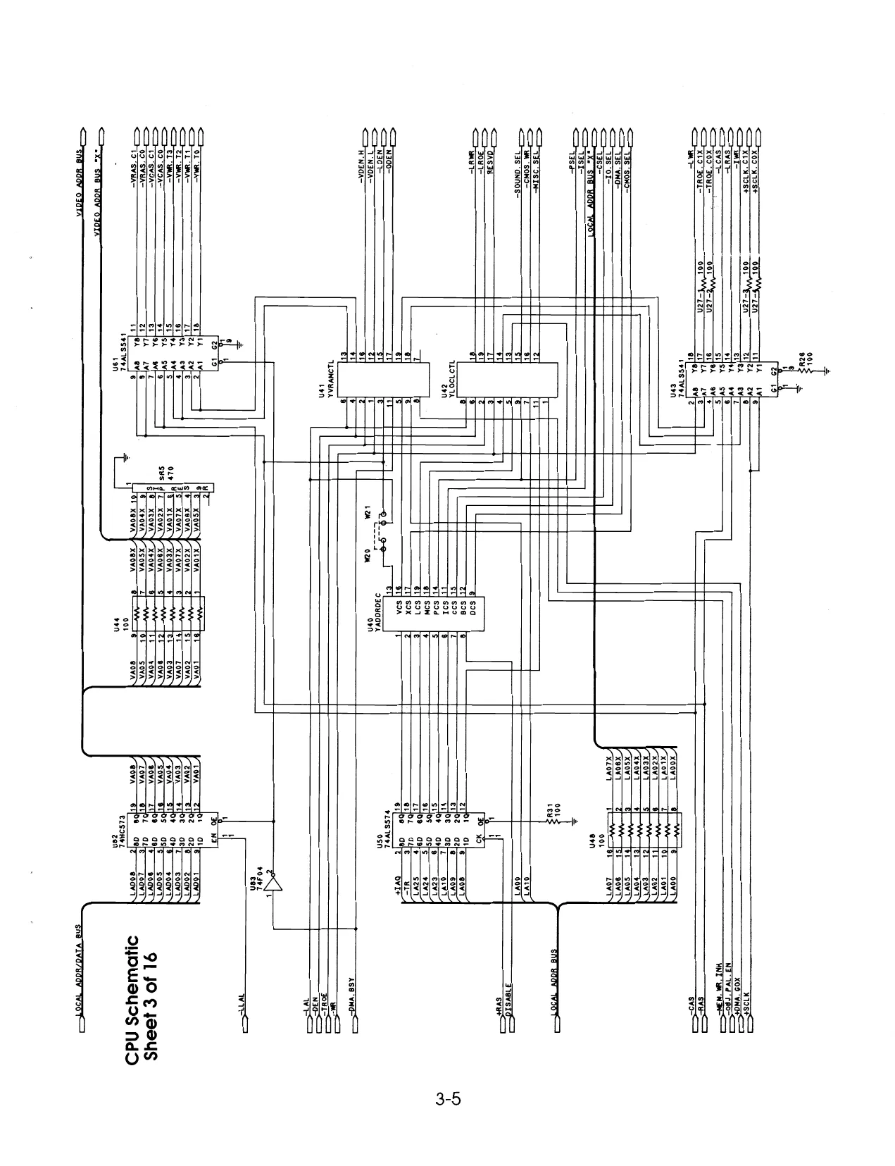
This page is a drawing, shown as the original scan.
PRPPRet =¥RAS. COX
CPU Schematic ue
Sheet 4 of 16 =SPK. 45 =SPK-9. O87, PAL. EN. TAERASE EN Leo. get 3c. scat —> 4F.SCALO
u1SC, SEL RESET 5,
3-6 cos. A12, NOS_AT! cos at ——— wo ss
COS. We cosinor coeSounD, SEL oc) 1S\DATA_ BUS A309
CPU Schematic
Sheet 5 of 16 PROGRAM MEMORY
LOCAL _ADDR BUS LOCAL_DATA BUS
uss ‘Yeuscere + EPs00 HEM, we INH f\
ce
ECCCCSC! 46x71 EXT. 19. A383 COIN. CNTRA. 2.7K 2 pT
LOCAL_ADDR/DATA BUS A39 . COIN. ENTA2 ~~
ENS uiAvee a 208s
RESET
MISC. 3EU
3-8
CPU Schematic
Sheet 6 of 16 JAAS. uns AUTOERASE 4 ¢
SND. INT, EP900 LAL
DISABLE
TOMA. BSY
SLINT2 GGG CAWGb GMa staat =l 5)
Tay 34 40MA, COX =LINT! PALETTE. SEL. =VRAS. C1
SR24~-10
TUaNOWTA Bsn
9130 £ fe0US SHOWOYIS Ndd ‘sn@ viva Wwoor
3-9
3-10 CPU Schematic Iwace wewony
Sheet 8 of 16 IMACE_ADDAESS @US S3SES55 CR, |
IROC, T3H = TROE Siusininn roe uh ae} te IMAGE DATA BUS
The
She se2vG" own 9L JO 6 89US oyoWesYss Ndd
yor He Xia 308 wt
xe er X01 WA XT wAS EI WAAR ee 09 “eruAs 09 S¥OAS 69 "30u1=—— = X19 “30¥I-< Oo WIOSF EILIZN XZOvA XEOVA X¥O¥A ESN EON
XLOVA
XeOvA
VOTE oS EMITS XT "S¥oA=— KIT wT 91 30 OL O0US oyoWSaYrS NddD
3-12
This page reads as a drawing: its text was drawn rather than typeset, and comes out in fragments. See the original scan.
3-14 ZERO, DETO ZERO. DET! sot AL =SDEN CRW =C0EN.
CAEN,
sé LIN. SPSEL RESVD
CPU Schematic ara Sheet 12 of 16 BLANK. x ¢ 5$p0r. CLK BLANK. x
us? YWRANSEQ EPeoe Mos. A12, ‘CNOS._AI SWATCH Doe
v7 TAAL S245 use TAALssT4
ova _—apt LSS WHL ny
vise WoL an
9L JO EL JO9US SyOWaYdsS Ndd
3-15
Preerreet
ma GORD oEr {aasn ef fer} aie OTE
+ {oxen 10N) oy Si WD (a3sn oof uy we oH SNS HOH
‘sA8 Vivd wOTOD mae NAS “AS 91 JO pL yeeUS DYOWSYIS NdD
3-16
3-17
CPU Schematic
Sheet 15 of 16
3-18
CPU Schematic °
Sheet 16 of 16
HIGH IMPACT FOOTBALL KIT JAMMA Chart
Ground Bk CH 1 Bk eval Ground tt«=*d
- Optional function- Game will operate without these.
3-19
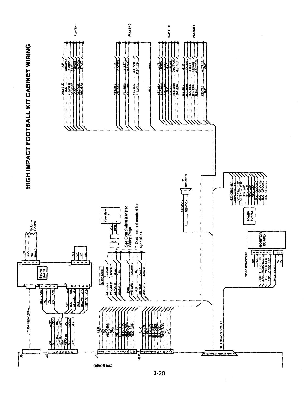
This page is a drawing, shown as the original scan.
HIGH IMPACT FOOTBALL KIT INTERBOARD WIRING
ba ng i JAMMA Edge Connector see THEE BI | E JAMMA CHART SBISBBERE E Not Used 1 ial F LF 123465678] [1294567891011 12
| 4 | From Audio Power to Audio. | 1 | a |
Board J5, Board J3
| NC | A | v2 | i |
ne 7
| NC | = | 3 |
| corer] ® | a | Y-UNIT CPU BOARD |
EUR |e F aLuRED[|o| 5 § BLU-BAN |< & KeY_ti5| 2 awake Tax He |
| WA JOB | From J4 On Audio Board | av | * | |
| Not Used | c- | [[ | etveea | Not Used |
fel ‘a j<|a
987654321 Pa <
| “4 | 8 | [= 1_|Reo P| | ||
| a | RIBBON CABLE | Power Fr | s | BLK |
| & aye | TOOPU | cru | s|o [Trev | |
| § mel? hus | bd | >» [shew |
a f= Hak AUDIO BOARD |» = NC 7 BLK ha
3-21
Coin Switch and Meter Wiring
Option 1
+5V
Meter
JAMMA Pin 16
JAMMA Pin 8
Option 2
JAMMA Pin 16
JAMMA Pin T JAMMA Pin 8
Wrong Way !
Coin Sw 1 ; JAMMA Pin T
JAMNA Pin 16
Do NOT Connect the coin switches this way. This Circuit is INCORRECT and will cause twice as many credits per coin.
ae 3% =
Tq —T
| 3 D/A. THRU 3Z "63 HOLES $ T oT
[ T | 233 (@
338 r4 DA. THRU se HOLES =
iZ
Ll —E 16-9/92 . EMILE, CONTROLS
PLAYER *
USED O/V 20/04 KIT
234 ——= / 7B DIA. THRU 3 hOLES
et DIA. THRU 3 \ HOLES dg 32% N
“= == a
/@-P/92—S TE/IIPLATE CONTROLS 324 PLAYER 2 USED ON FO/OF AIT
of
a (8 Dial ES
—/$ 333 {— _
Te + 1B age | t L
4 _ - L
- 3 =| é rye Y EM PLATES CONTROLS 325 PLAYER * 3 USED ON FOsOF K/T
/3 DIA. THRU 3 HOLES
ma)
a
a7 ISS / 32 re 7 na + > 2 Se | 3e | y vu
LD LY = 3 ~
3 DIA.THRY 16 -WI92 -3 FHOLES TEMPLATE, CONTROLS 326 PLAYER eZ USED ON FO/OF KIT
NOTES:
WARNINGS & NOTICES
- For safety and reliability, substitute parts and modifications are not recommended.
- Substitute parts or modifications may void FCC type
- This game is protected by federal copyright, trademark and patent laws. Unauthorized modifications may be illegal under Federal law. This also applies to WILLIAMS logos, designs, publications and assemblies, Moreover, facsimiles of WILLIAMS equipment (or any feature thereof) may be illegal under federal law, regardless of whether or not such facsimiles are manufactured with WILLIAMS components.
Notice When Williams Electronics ships a game it is in compliance with FCC regulations. Your sticker is proof. If the sticker is missing or damaged, legal repercussions to the owner or distributor of the game may result. If your game kit does not contain an FCC sticker, call Williams Electronics immediately.
Notice No part of this publication may be reproduced by any mechanical, photographic, or electronic process, or in the form of a phonographic recording, nor may be transmitted, or otherwise copied for public or private use, without permission from the publisher.
Entire contents of this manual copyright © 1990 WILLIAMS ELECTRONICS GAMES, INC. All Rights Reserved.
WILLIAMS ELECTRONICS GAMES, INC. 3401 N. CALIFORNIA AVE. CHICAGO, IL 60618
FOR SERVICE:
CALL YOUR AUTHORIZED WILLIAMS DISTRIBUTOR.