Indiana Jones and the Temple of Doom TM-282 1st Printing
Indiana Jones and the Temple of Doom (set 1) (Atari Games, 1985) · Technical Manual · 52 pages · 48 sections · original scan
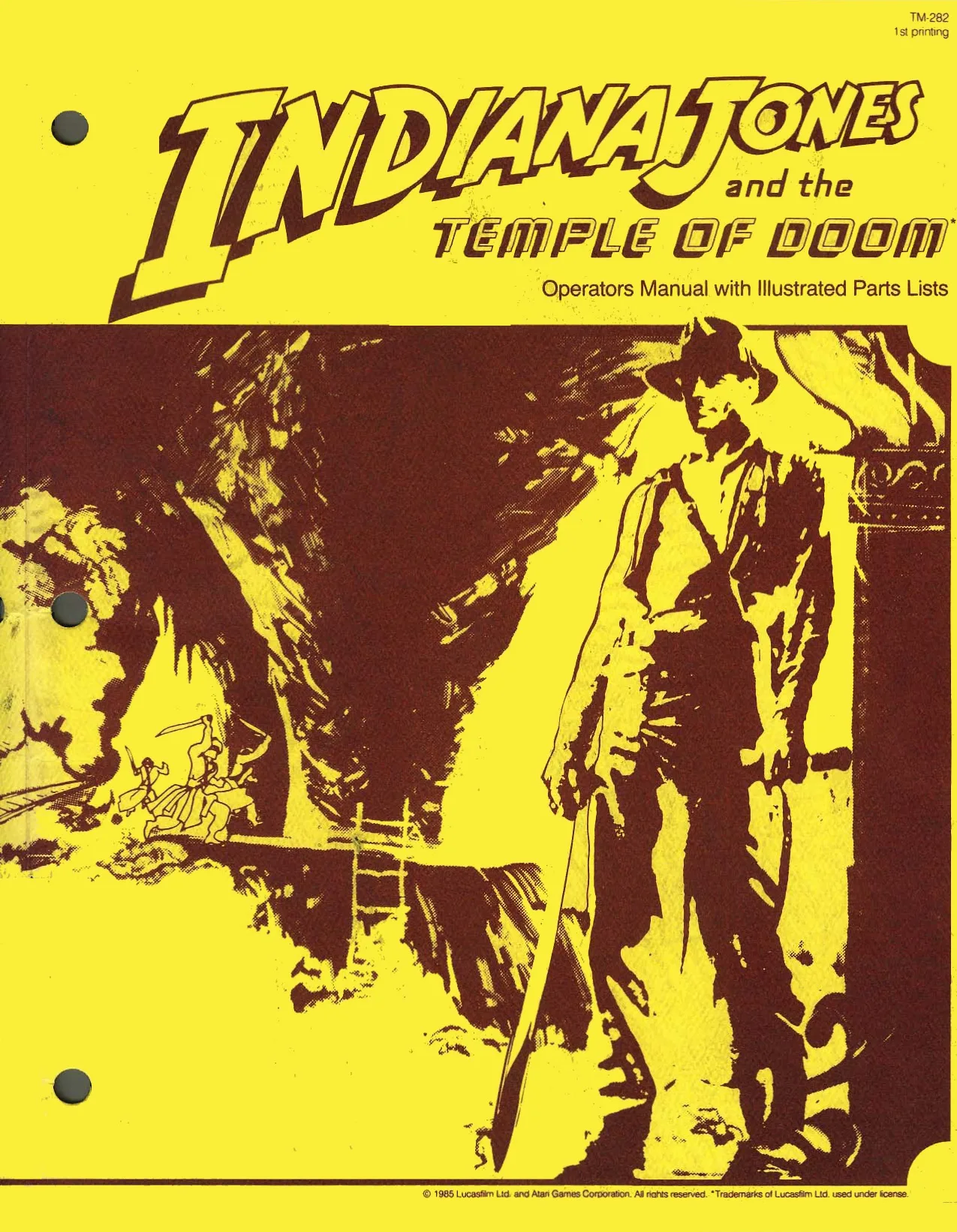
This page is a drawing, shown as the original scan.
Atari Games Corporation Customer Service
If reading through this manual does not lead to solving a certain maintenance problem, call TELEHELP® at one of these Atari Games Customer Service offices:
UNITED STATES
Parts and Service
California Customer Service Office 737 Sycamore Drive P.O. Box 906 Milpitas, CA 95035 Telex 17-2976 (Monday-Friday, 7:30-4:00 pm Pacific Time) OF (408) 434-3950
EUROPE
Parts and Service
European Customer Service Office Tipperary Town, Ireland Telex 28165 (Monday-Friday, 9:00-6:00 pm GMT) = 062-52155
Vj, ONE ES
We the
TEMPLE OF POe@m
Operators Manual with illustrated Parts Lists
INDIANA JONES AND THE TEMPLE OF DOOM
© 1985 by Lucasfilm Ltd. and Atari Games Corporation All rights reserved No part of this publication may be reproduced by any mechanical, photographic, or electronic process, or in the form ofa phonographic recording, nor may it be stored ina retrieval system, transmitted, or otherwise copied for public or private use, without permission from the publisher. The game play, all graphic designs, this technical manual, its accompanying schematic diagrams, and the display manual are protected by the L opyright Act of 1976. This Act provides for increased penalties for violating federal copyright laws. Courts can impound infringing articles while legal action is pending. If infringers are convicted, courts can order destruction of the infringing articles. In addition, the Act provides for payment of statutory damages of up to $250,000 in certain cases. Infringers may also have to pay costs and attorneys’ fees and face an imprisonment of up to five years. Atari Games Corporation will aggressively enforce its copyrights against any infringers. We will use all legal means to immediately halt any manvfacture, distribution, or operation of acopy of video games made by us. Anyone who purchases such copies risks forfeiting such a game.
Published by Atari Games Corporation 1272 Borregas Avenue P.O. Box 3618 Sunnyvale, California 94088
Printed in the U.S.A. 8P
INDIANA JONES AND THE TEMPLE OF DOOM
Notice Regarding Non-ATARI Parts
You may void the game warranty (printed on the inside back cover of this manual) if you do any of the following: © Substitute non-ATARI parts in the game. © Modify or alter any circuits in the game by Corporation. sing kits or parts not supplied by Atari Games
NOTE
This equipment generates, uses, and can radiate radio frequency energy and if not installed and used in accordance with the instruction manual, may cause interference to radio communications. It has been tested and found to comply with the limits for a Class A computing, device pursuant to Subpart] of Part 15 of Federal Communications Commission (FCC) Rules, which are designed to provide reasonable protection against such interference when operated in a commercial environment. Operation of this equipment in a residential area or modification to this equipment is likely to cause interference in which case the user, at his own expense, will be required to take whatever measures may be required to correct the interference. If you suspect interference from an ATARI® game at your location, check the following: © All green ground wires in the game are properly connected as shown in the game wiring diagram. © The power cord is properly plugged into a grounded three-wire outlet. ¢ The game printed-circuit boards (PCB) are properly installed with the Electromagnetic Interference (EMI) ground plane. If you are still unable to solve the interference problem, please contact Customer Service at Atari Games Corporation. See the inside front cover of this manual for service in your area.
Vv INDIANA JONES AND THE TEMPLE OF DOOM
Table of Contents
Installation How to Use This Manual Introduction... Kit Parts Invento! Tools Required. Conversion Instructions . Setting the Coin and Game uae Operator Hints . tavenaveny
Self-Test RAM/ROM Test... Switch Test.. Coin Options. Game Options Statistics ... Histogram: Playfield Test and Joy Motion Object Test....... Motion Object Picture Test Motion Object Height Test Alphanumerics Tes Color Test... : Color Purity Test . Convergence Test. Sound Test
Maintenance Preventive Maintenance. Removing the Control Panel Joystick Control...
Corrective Maintenance .... Removing the Player Start Switches .. Removing the Joystick Assembly... Disassembling the Joystick Assembly
Game Play Storyline Operating Mode: Game Play........ Hints for Game Play Maximizing Earnings
Illustrated Parts List See List of Mlustrations that follows. SEGSEEL
PRY yYYYNyyyyyyny BUUNDKDARAARAAAS SND
INDIANA JONES AND THE TEMPLE OF DOOM
List of Illustrations
Figure 1-t Figure 1-2 Figure 1-3 Figure 1-4
Figure 2-1 Figure 2-2 Figure 2-3 Figure 2-4 Figure 2-5 Figure 2-6 Figure 2-7 Figure 2-8 Figure 2-9 Figure 2-10 Figure 2-11 Figure 2-12 Figure 2-13 Figure 2-14 Figure 2-15 Figure 2-16
Figure 3-1 Figure 3-2 Figure 3-3
Figure 5-1 Figure 5-2 Figure 5-3
Table 1-1 Table 2-1 Table 2-2 Table 2-3 Conversion Kit Part Locations .. Attraction Film Replacement. Control Panel Replacement... : Cartridge PCB Replacementt.........:.:c cece
ROM Test Fails .......0.ccceeeesceeeeeseeteeeeees
Coin Options Game Options . Statistics....... Histograms (One of Six Screens) Playfield Test .. Motion Object Test Motion Object Picture Test . Motion Object Height Test Alphanumerics Test .. Color Tesi... Color Purity Test. Convergence Test.. Sound Test.......
Control Panel Remova
‘mbly and Lubrication ..
Control Panel Assembly Joystick Assembly .. LSI Cartridge PCB Assembly ..
List of Tables
Kit Parts Inventory Faulty ROM Locations. Coin Option Settings Game Option Settings. yp yt ty SYYUU AD
2-2
2-4
vi INDIANA JONES AND THE TEMPLE OF DOOM
Safety Summary
The following safety precautions apply to all game operators and service personnel. Specific warnings and cautions will be found throughout this manual where they apply.
& WARNING A Properly Ground the Game. Players may receive an electrical shock if this game is not properly grounded! To avoid electrical shock, do not plug in the game until it has been inspected and properly grounded. This game should only be plugged into a grounded threewire outlet. If you have only atwo-wire outlet, we recommend you hire a licensed electrician to install a grounded outlet. Players may receive an electrical shock if the control panel is not properly grounded! After servicing any parts on the control panel, check that the grounding clip is firmly secured to the metal tab on the inside of the control panel, Only then should you lock up the game. AC Power Connection. Before connecting the game to the AC power source, verify that the proper voltage-selection plug is installed on the game’s power supply. Disconnect Power During Repairs. To avoid electrical shock, disconnect the game from the AC power source before removing or repairing anv part of the game. When removing or repairing the video display, extra precautions must be taken to avoid electical shock because high voltages may exist within the display circuitry and cathode-ray tube (CRT) even after power has been disconnected. Do not touch internal parts of the display with your hands or with metal objects! Always discharge the high voltage from the CRT before servicing this area of the game. To discharge the CRT: Attach one end of a large, wellinsulated, 18-gauge jumper wire to ground. Momentarily touch the free end of the grounded jumper to the CRT anode by sliding it under the anode cap. Wait two minutes and discharge the anode again. Use Only ATARI Parts. To maintain the safety integrity of your ATARI game, do not use non-ATARI parts when repairing the game. Use of non-ATARI parts or other modifications to the game circuitry may adversely affect the safety of your game, and injure you or your players. Handle Fluorescent Tube and CRT With Care. If you drop a fluorescent tube or CRT and it breaks, it may implode! Shattered glass can fly six feet or more from the implosion. Use the Proper Fuses. To avoid electrical shock, use replacement fuses which are specified in the parts list for this game. Replacement fuses must matcii those replaced in fuse type, voltage rating, and current rating. In addition, the fuse cover must be in place during game operation.
Installation
How to Use This Manual
This manual is written for game operators and service technicians and describes how to install, test, and maintain your INDIANA JONES AND THE TEMPLE OF DOOM” game. Your TEMPLE OF DOOM™* game uses the Atari Games System ' cabinet, which is designed to accept the necessary hardware to easily convert the System I cabinet into a variety of games. Consequently, this manual contains information that applies to those parts of your existing System I cabinet that are added or replaced to convert the cabinet for the TEMPLE OF DOOM game (see Figure 1-1). Information that applies to those parts of the System 1 cabinet that are common to ail games is contained in a separate System | Operators Manual (TM-277), included with your System [ cabinet. Where applicable, references are provided in this manual to the System I Operators Manual.
This manual contains the following information on the ‘TEMPLE OF DOOM game:
- Chapter | provides a kit parts inventory, conversion instructions, inspection procedures, and option setting information. Chapter 2 provides self-test procedures (includes procedures for setting the coin and game options). Chapter 3 provides maintenance information for the Joystick Assembly and the player-start pushbutton switches Chapter 4 provides game play information. Chapter 5 provides illustrated parts lists for the controlpanel assembly, Joystick Assembly, and TEMPLE OF boom Cartridge Printed-Circuit Board (PCB). Wiring and schematic diagrams for the TEMPLE OF DOOM contro! panel and Cartridge PCB are contained in the SP-282 Schematic Package Supplement included with this manual. Refer to the Schematic Package Supplement included with the System J Operators Manual for the wiring and schematic diagrams that apply to the Systera [ cabinet hardware
Chapter 1
tg ara Alan Garres Criporaion Ail ngrts reserved rademark of Lucasfilm Ltd. used by Atari Games Cororation under license.
Installation INDIANA JONES AND THE TEMPLE OF DOOM
Attraction Film See Figure 1-2
Joystick Assy See Figures 3-2 and 33
Control Panel Assy See Figures 1-3 and 3-1
Product ID Label {not shown)
Cartridge PCB Assy
Self-Test Label (not shown)
Figure 1-1 Conversion Kit Part Locations
INDIANA JONES AND THE TEMPLE OF DOOM
Introduction
This chapter includes the instructions necessary for converting your existing System I game into a TEMPLE OF DOOM game. The conversion instructions include: (1) removing the existing attraction film, contro! panel, and Cartridge Printed-Circuit Board (PCB); and (2) installing a ‘TEMPLE OF DOOM attraction film, Cartridge PCB, and control panel. Refer to Figure 1-1 for the locations of the parts of the System I cabinet that are replaced.
Kit Parts Inventory The assemblies listed in Table 1-1 are included in the TEM- PLE OF DOOM Conversion Kit. Refer to Chapter 5, Ilustrated Parts Lists, for a description of the component paris comprising the control panel and Cartridge PCB assemblies listed in Table 1-1.
Tools Required The only tools required to perform a complete TEMPLE OF DOOM game conversion are a Phillips screwdriver, and a 1/8-inch hex driver.
Conversion Instructions
ay WARNING —__& Toavoid electrical shock, unplug the game before performing the conversion procedures.
Table 1-1 Kit Parts Inventory A043301-01
Part No. Quantity Description
| A043302-01 | 1 | Control Panel Assembly |
| A043307-01 | 1 | Cartridge PCB Assembly |
| 038158-01 | 1 | Product Identification Label |
(without UL logo) OR
| 038158-02 | 1 | Product Identification Label |
(with UL logo)
| 043304-01 | 1 | Attraction Film |
| SP-282 | 1 | TEMPLE OF DOOM Schematic |
Package Supplement
| ST-282 | 1 | TEMPLE OF DOOM Self-Test |
Labe}
| TM-282 | 1 | TEMPLE OF DOOM Operators |
Manual Insaallation
The following procedures are arranged in the sequence recommended for performing the game conversion. The parts of your cabinet that are affected by the conversion are removed first and then replaced by the new TEMPLE OF DOOM kit parts
Replace the Attraction Film Perform the following procedure to remove/replace the existing attraction film with the TEMPLE OF DOOM attraction film (see Figure 1-2).
- Turn off the game power. 2, Use a 1/8-inch hex driver to remove the three screws and washers securing the upper retainer to the top of the cabinet
- Grasp the top edge of the existing attraction film behind the attraction shield and slide it up to remove.
- Install the TEMPLE OF DOOM attraction film. Make sure the film is fully inserted into the bottom slot.
- Replace the upper retainer.
Replace the Control Panel Perform the following procedure to remove/replace the existing control panel with the TEMPLE OF DOOM control panel (see Figure 1-3).
- Unlock and open the coin door on the front of the cabinet.
. Carefully reach through the coin door opening and release the spring-draw latch located under the control panel on the right side of the cabinet.
- Unlock and remove the front access panel.
- Reach through the front access-panel opening and disconnect the control-panel harness from the top of the Main PCB.
- Carefully reach up under the top of the front access- Panel opening and release the spring-draw latch located under the control panel on the left side of the cabinet. nm
- From underneath, push up on the front edge of the control panel to free the panel from the siot in the cabinet.
- Disconnect the green ground wire from the controlpanel harness and remove the control panel from the cabinet.
- Install the TEMPLE OF DOOM control panel in the reverse order of removal. Refer to Figure 3-1 for the proper
Insrallation INDIANA JONES AND THE TEMPLE OF DOOM
Upper Retainer ? Attraction Shield re “EEE Attraction Film
Coin Door Front Access Panel
Figure 1-3 Control Panel Replacement
control-panel harness connections to the Main PCB. 1. Turn the cabinet power off. Make sure the green ground wire is connected to the 2. Unlock and remove the front access panel from the control-panel harness. cabinet.
- Turn the four thumbscrews (some System I games. Replace the Cartridge PCB may have Phillips screws) that secure the existing Car- Perform the following procedure to remove/replace the tridge PCB to the ground plane. ; existing game Cartridge PCB and replace with the TEMPLE 4, Gently disconnect the Cartridge PCB from the Main OF DOOM Cartridge PCB (see Figure 1-4). PCB.
INDIANA JONES AND THE TEMPLE OF DOOM
wn
6. Main PCB
Cartridge PCB Installation
Ground Plane
Figure 1-4 Cartridge PCB Replacement
- Connect the TEMPLE OF DOOM Cartridge PCB to the Main PCB. Make sure that the Cartridge PCB is fully inserted into the Main PCB edge connectors.
Replace the four thumbscrews on the Cartridge PCB. Refer to Figure 1-1 for the locations of the printedcircuit boards
Staple or tape the TEMPLE OF DOOM self-test label on the inside of the front access panel.
Install the Product Identification Label
Perform the following procedure to install the TEMPLE OF boom product identification label. 1, Remove the protective backing from the TEMPLE OF boom product identification label.
- Place the TEMPLE OF DOOM product identification label over the existing product identification label on the back of the cabinet.
Installation
Inspect the Game Before applying power, perform the following inspection procedure, lL. Carefully check that the TEMPLE OF bOOM Conversion kit parts have been properly installed. Make sure the contro-panel harness connector is tightly connected and that the spring-draw latches under the control panel are securcly fastened Regularly clean the air filter at the back of the game (located in front of the fanj. Use a vacuum cleaner to remove dust from the filter, vacuuming the dust in the opposite direction of the air flow, If a vacuum cleaner is not available, remove the filter and wash it with any mild detergent. Let the filter dry thoroughly betore replacing it in the frame. Equipment failure can result from dust accumulation if the filter is not replaced
- Plug in the game power.
- Perform the selfiest procedure as given in Chapter 2 of this manual. [f the self-test indicates that the display requires adjustment, perform the adjustment procedures described in the display manaal ‘hen you are confident that all instractions w properly followed, close and lock the front panel
Setting the Coin and
Game Options
The TEMPLE OF DOOM Coin and game options are set in the Self-Test Mode. Refer to the options display described in Chapter 2 for the recommended settings and the procedure for setting the options.
Operator Hints
Your System I cabinet with the TEMPLE OF DOOM game uses. fe ¢ audio than previous games, which results in more player involvement and enjoyment. The System 1 games use advanced, digital, sound-generation tech-
1-6 INDIANA JONES AND THF TEMPLE OF DOOM,
niques to create realistic musical instrument sounds (such as clarinets, harmon drums, and violins), Although a player may not be consciously aware of the music, it has a direct ¢ffect on the excitement and emotional experience of the game. The TEMPLE OF DOOM game creates ez itching sound effeets, which are designed to give feedback to make the player believe that the game is responding directly to his actions, To maximize the player's enjoyment of this en hanced audio, we are providi one hints for the operator:
- The game location should be a relatively dead acou! tical environment, The goal is to minimize unneces y sound reflection, so that the sounds from the TEMPLE OF DOOM game won't be drowned our by the accumulation of other sounds that bounce around the room. Carpets help climinate sound reflections from the floor. Acoustical tile is also useful, especially if you have low ccilings. Ifyou use an environmental sound system or a stereo, consider lowering its volume or perhaps even turning it off. In the days when video games just made harsh beeps and boops, a central sound system helped make up for the lack of drive and excitement in a game's sounds, But your TEMPLE OF DOOM game is Very MiUsical, and a sound systeni interferes with the game's ability fo interest players and draw bystanders.
- Be concemed with the overall volume levels in arcade environments. The goalis to involve the players’ emotions, not to damage their hearing. To a certain point, raising the game volume helps add to player excitement, but above that level it creates hearing fatigue and the high volume starts to drive players away, Rather than turning up the volume on the TEMPLE OF hooM games to cut through the background sound level, wy lowering the volume of any neighboring, games that have sounds which are not an attractive or
1984 t ucaslen Lal npntsreserved
Self-Test
After the self-test switch is set to the on position, 16 selftest screens provide a visual and audible check of the 1n- DIANA JONES AND THE TEMPLE OF DOOM game Circuits. On System I games, the self-test switch is typically located on the Regulator/Audio PCB. When the self-test switch is turned on, and the power is then turned on, the game enters the full Self-Test Mode. If the self-test switch is turned on any other time, then the game will enter a shorter Self-Test Mode. The following self-test screens are arranged in the sequence in which they occur after the self-test switch is first turned on. After the Sound Test, the sequence starts over with the Switch Test. Turning the self-test switch off at any time during the Self-Test Mode causes the game to return to the Attract Mode.
Chapter 2
Self-Test
RAM/ROM Test ‘The RAM/ROM Test, as shown in Figures 2-1 and 2-2, provides a visual Check of the game RAM, ROM, and associated circuitry. Ifthe RAM and ROM test passes, the display will switch to the Switch Test. The RAM/ROM Test is divided into two sections. The condition of the RAM circuitry is displayed in the bottom half of the screen and, after about an eight-second delay, the condition of the ROM circuitry is displayed in the top half of the screen. An error message indicates that the RAM, ROM, or associated circuitry may be faulty. If the ROM test fails, the error messages May appear in the top half of the screen as shown in Figure 2-1. Refer to ‘Table 2-1 for the faulty ROM locations. If the upper or lower main memory ROM circuits on the Main PCR fail, an Upper or Lower Main ROM Error message will appear at the top of the screen, Press the player 1 start button to obtain any RAM or ROM error message(s) from the Cartridge PCB RAM or ROM circuits. Press the player 1 start button again. if the bank switch ROM citcuits on the Cartridge PCB are faulty, the message Bank Switch Error will appeat.
Figure 2-1 ROM Test Fails
Ram error at: A00000 Wrote: C000 Read: 8000
Figure 2-2 RAM Test Fails INDIANA JONES AND THE TEMPLE OF DOOM
Table 2-1 Faulty ROM Locations
Error Message Location
ROM ar 10000 error 10B 10A ROM at 18009 error 108 10a ROM at 20000 error 12B
ROM at 28000 error 12B
ROM at 36000 error 14B 14a ROM at SLAPSTIC error = 16B L = 16A
Figure 2-3 Switch Test
If the RAM test fails, the error messages appear as shown. in Figure 2-2. Refer to the memory maps and schematic diagrams in the schematic package supplements for this manual and for the System I Operators Manual to determine the location of the faulty RAM circuit.
Repair the faulty RAM or ROM circuit or press the player 1 start button to obtain the Switch Test.
Switch Test The Switch Test appears as shown in Figure 2-3. This test indicates the condition of the player 2 start pushbutton switch. Press the player 2 start button and note that the first number changes to a |. Press the player 1 start button. to obtain the next screen.
Coin Options The Coin Options screen appears as shown in Figure 2-4. This screen indicates the current coin-option settings and is usecl to Change the coin option settings. Refer to Table 2-2 for the available and recommended settings.
INDIANA JONES AND THE TEMPLE OF DOOM
Ogos t pape Tete RAT Tenn
Boone te erase 8 Pies,
Coin Options Figure 2-4
Table 2-2 Coin Option Settings
Option Name Available Settings
1 Coin 1 Credit 2 Coins 1 Credit 3 Coins | Credit 4 Coins 1 Credit Credit Mode
1 Coin Counts as 1 Coin 1 Coin Counts as 4 Coins 1 Coin Counis as 5 Coins 1 Coin Counts as 6 Coins Right Mech Multiplier
1 Coin Counts as 1 Coin 1 Coin Counts as 2 Coins Left Mech Mukiptier
No Bonus Adder <4 2 Coins Give 1 Exua Coin 4 Coins Give | Extra Coin 4 Coins Give 2 Extra Coins 5 Coins Give 1 Extra Coin 3 Coins Give 4 Extra Coin Free Play Bonus Adder
4 Manufacturer's recommended settings,
Coin Mode should have a red or green box around it. Move the joystick right or left, and note that the coin mode values change. Select the desired value. Move the Joystick down to move the red or green box to Right Mech Multiplier. Move the joystick right or left to cycle through al) the lable multiplier values. Select the desired value, Repeat this procedure for the remaining opions.
If you want to cancel the option changes and restore the previous settings, press the player 2 start button. Pressing the player 1 start button will set the options as shown on. the screen and will advance you to the Game Option screen. Sinepl ing from tbe self-test by moving the seljtest switch to “off” will not save any changed Settings. Seif-Test
Game Options
The Game Options screen appears as shown in Figure This screen indicates the current option settings, use this screen to reset the high-score table and change the game option settings. Refer to Table 2-3 for the available options and the recommended settings. Note that the recommended settings arc displayed in green. Move the joystick right or left and note that the settings for the option in the shaded block will change. Select the desired value. Move the joystick up or down to move the desired option into the shaded block. Move the joystick right or left to cycle through all the available option settings. Select the desired value, Repeat this procedure for the remaining options, If you wish to cancel the option changes and restore the original settings, press the player 2 start button. Press the player 1 start button to set the game for the options selected and obtain the Statistics screen.
Statistics The Statistics screen appears as shown in Figure 2-6. This screen provides a visual check of the current game statistics. The statistics information is accumulated either from the first time the game was turned on or from the last time the statistics were reset. Reset the statistics information by pressing the player 2 start buiton. The following information appears on the Statistics screen:
- Aux coins is Not used On the INDIANA JONES AND THE TEMPLE OF DOOM game,
Sqne Options giex isk Soern Yobie ort (ees Sqpe Ee arvanct
atest Sant cottinn Sei Sees WS Sattine ana exit
Figure 2-5 Game Options
Self-Test INDIANA JONES AND THE TEMPLE OF DOOM
Table 2-3 Game Option Settings
Option Name Available Settings Comments
Reset High-Score Table
Demo/Play Mode
Restore Factory Opiions
Sounds in Attract Mode
Automatic Reset of High-Score Table
Number of Starting Lives
Maximum Number of Extra Lives
Game Difficulty
Extra Life Intervals (Extra Life Granted ai) ‘Yes <4 No.
Playable mode <4 Demonstration mode
Yes No <4
On< Off
On <4
lives for one credit/? lives for two credits <4
5~
Fasy Medium <4 Hard Real, real hard
10,000, 30,000, 66,000, 109,006, 150,009, 200,006, 300,000, and 400,000 points 20,000, 50,000, 100,000, 150,000, 200,000, 300,000, 400,000, and 500,000 points ~ 30,000, 75,000, 150,000, 250,000, 350,000, 450,000, 550,000, and 650,000 points 50,000, 125,000, 250,000, 400,000, 600,000, 800,000, 1,000,000, and 1,200,000 points 20,000, 40,000, 60,000, 80,000, 100,000, 120,000, 140,000, and 160,000 points 30,000, 60,000, 90,000, 126,000, 159,000, 189,000, 210,000, and 240,000 points 40,000, 80,000, 120,000, 160,000, 200,000, 240,000, 280,000, and 320,000 points No extra fives granted Free play mode for demonstration only, Press both start buttons simultaneously to advance (o next wave.
Table is reset to factory scores and initials every 2,000 plays but no less than 200 plays since the last person entered initials. If this is set to “on”, you should also set the Reset High-Score Table option to “‘yes.””
Screen shows ‘‘Increasing from 10,000 points” Screen shows “Increasing from 20,000 points” Screen shows “Increasing from 30,000 points” Screen shows ‘‘Increasing from 50,000 points’ Screen shows “Every 20,000 points”
Screen shows “Every 30,000 points”
Screen shows ‘Every 40,000 points”
“4 Manufacturer's recommended settings
INDIANA JONES AND THE TEMPLE OF DOOM
estaadef steuistics” Ppervulstestena
Figure 2-6 Statistics
Left coins shows the number of coins deposited in the left coin mechanism. Right coins shows the number of coins deposited in the right coin mechanism. 7 plyr Games shows the number of 1-player games. 2 plyr Games shows the number of 2-player games. Mins played shows the total time, in minutes, of all the games played. Mins pwr up shows the total time, in minutes, that the game has been turned on. Aux. cntr 1 shows the games played up to the final bridge wave on the Easy level. Aux. cntr 2 shows the total number of extra lives earned in Easy level with 1 credit. Aux. cntr 3 shows the number of games played on the 7 lives for 2 credits factory-recommended setting. Error count shows the number of EEPROM errors that were detected. Replace the EEPROM at location 15F on the Main PCB if the errors detected exceed approximately 25 per week. Avg. Game Time shows the average game time per play in seconds. Press the player 1 start button to obtain the Histogram Screen.
Histograms
Six Histogram screens are provided in this game; one of them is shown in Figure 2-7. Histogram levels 1-3 show the total game times for all games played with one credit, as follows: Level 1 Easy level select Level 2 Medium level select Level 3 Hard level select The Histogram levels 4-6 show total game times for all games played with two credits, as shown below. However, Self-Test
Histesrem fer level 1
High score fer levet: 112696 | butt epee Settee te
Figure 2-7 Histograms (One of Six Screens)
if you do not use the 3 lives for 1 credit/7 lives for 2 credits game option setting, your game’s screen will show zeroes for high scores and no histogram bars in Levels 4-6. Level 4 Easy level select Level 5 Medium level select Level 6 Hard level select Select each Histogram level screen by pressing the player 1 start button. These six screens show the game times from 0 to 540 seconds. Also displayed is the high score for each level The game times information is accumulated either from the first time the game was turned on or from the last time the game times were reset. Reset the Histograms by pressing the player 2 start button while displaying the Histogram Level 6 screen. Press the player 1 start button to obtain the Playfield Test.
Playfield Test and Joystick Test The Playfield Test indicates the condition of some of the graphics ROM, the vertical and horizontal playfield scrolling registers, and the joystick control. The display (see Figure 2-8) should not show any abnormalities. Move the joystick control to the left. The playfield should slowly scroll to the left. Move the joystick control up and the playfield will scroll up—likewise for right and down. As you move the image Of INDIANA JONES up, you should see 16 uniquely colored boxes on the screen—the same colors as used in the picture of INDIANA JONES. Press the player 1 start button to obtain the Motion Object Test.
Motion Object Test The Motion Object Test appears as shown in Figure 2-9, This test indicates the condition of the motion-object buffer circuit. The seven groups of eight motion objects should be identical and eight pixels high.
Self-Test
Figure 2-8 Playfield Test
: Motion Opsert Test Pereeter Sutter e
for Rand Eaaee ttn
Figure 2-9 Motion Object Test
Press the player 2 start button to select any of the 56 motion objects. ff the Joystick is moved, the selected motion Object should move in the same direction. Press the player | start button to obtain the Motion Object Picture Test.
Motion Object Picture Test The Motion Object Picture appears as shown in Figure 2-10. By moving the Joystick up or down the pictures: should change. By selecting all of the available pictures, you can see the state of the graphics ROMs. Press the player 1 start button to obtain the next test
Motion Object Height Test
The Motion Object Height Test appears as shown in Figure 2-11. This test indicates the condition of the motion object/playfield graphic address generator circuit. Observe the rightmost column: the top 14 boxes in it should be uniquely colored. From top to bottom, the colors should be: royal blue, light blue, black, dark tan,
INDIANA JO
AND THE TEMPLE OF DOOM
hy
Figure 2-10 Motion Object Picture Test
| Nation Ohicet Heteht Test
Figure 2-11 Motion Object Height Test
dark purple, yellow, deep rust, olive green, red, black, light grey, dark cranberry, light cranberry, and light tan The color pattern of the rightmost column can be used. to find errors in the bit plane circuits. Press the player | start button to obtain the next test.
Alphanumerics Test The Alphanumerics Test should appear as shown in Figure 2-12. This test indicates the condition of the alphanumerics circuit Press the player i start button to obtain the Color Test
Color Test The Color Test appears as shown in Figure 2-13. This test indicates the condition of the display color circuits. There should be eight vertical gray-scale bars and three groups of eight horizontal bars with shades of red, green, and blue. The brightest bars should be on the left, and the darkest (black) bars should be on the right with a bright white frame around the screen. This frame will help to
INDIANA JONES AND THE TEMPLE OF DOOM
Figure 2-13 Color Test
identify the darkest color band. If the display characteristics are not correct, refer to the display manual for the color-gun adjustment procedure or to determine the possible cause of failure.
Pre Test. the player 1 start button to obtain the Color Purity
Color Purity Test
The Color Purity Test consists of five color displays that indicate the condition of the display color-purity circuits. The first display to appear should be a red screen with the word RED displayed at the bottom of the screen as shown, in Figure 2-14, Press the player 2 start button and the next display to appear should be green with the word GREEN displayed at the bottom of the screen. Press the player 2 start button to obiain a blue, white, and finally a gray screen. After the gray screen, the display will repeat the white screen again. If the display characteristics are not correct, refer to the display manual for the color-purity adjustment procedure or the possible cause of failure. Self-Test
Figure 2-14 Color Purity Test
PPE Ceaversenee Tent cee titts Bogoggoo An WoW AACA sopancagasgccs PoosrocoeagecagaobegeecenHoES Soe sae DES eS BocosueGou sce uaGHcasnsesconSDcOoeREE AD SSS pordossoosoos 2oocco oko econo skosogacccoss Busses ges ooocoecancasnossauposacsaopoESS Bose SoOCRD CN GOR Gob osbooCE SOOSOREEnoSSE BOSS eGo OGESGuaGooccDaLe OSE DESO oEoES SESsSOCOS Huon oot ean eo RODD SS GeDcesesces Sead sce cascroscesboseGoco DOCH RSEREGE Se Q5aeSougoGnarSoanecosGkoeotoasoemaEesa SSoaseeonso ce oooasscsccccocgessouose as PEGG RCS SSoe GOPCe So oR MOORS caSHESekepeSS: Sougevcccasossgcnaat ron ooo soeaRsouBBeD! Gaoegaeooaonsosossestacconsasosagances) SeqscccocesnenoumoUnnon se sasanag SBaoES! BROS Scr aged Soo SDSR OTe coos OCC RSBEBSERGE: Souccaceguo ccs seonoescsnosenaaaRaooBEE: Sssncnsccce soudococorcosscosnageeanect SUSsesogoaog somos eAcoogss conoasoOSeeoR BSsdspososs con seoncononokcasereoRoseast Bog socGeGasdn tons conc sos BHODSESoRaD: RGRGORGOR on enGooRGUDORcOnGRDgAOsaDeD TET Sooghocoaes oooceosgoGooRoAgsGgnooneaRt UGusoSodnaodotggobenosnoosonoRo eG oRoDEot BHORGoeoooooooDcosbHeosoodEDeGogsoRoRTE PECEEEEEEE CEE EREEE ELLE ERE EE Ere eg P GRgaSoooDgsogo et Be i BeSSeeesgeseease: Figure 2-15 Convergence Test
Press the player 1 start button to obtain the Convergence Test,
Convergence Test The Convergence Test appears as shown in Figure 2-15. The grid pattern should be white. This test indicates the condition of the display size, centering, linearity, and convergence. Press the player 2 start button, and the pattern should turn violet. Repeated pressing of the player 2 button should cause the screen to alternate between violet and white. Check the grid pattern for the following characteristics: © The four corners of the frame around the grid pattern. should touch all four corners of the screen.
- Grid lines should exhibit no pincushioning or barreling, and the lines should be straight within 3.0 mm. « Violet and white pattern convergence should be within 2.0 mm. If the display characteristics are not within these limits, refer to the display manual for the linearity and conver-
w at
Self-Test
gence adjustment procedures or to determine the po: ble cause of failure.
Move the joystick up, and the pattern should slowly scroll up the screen, Moving the joystick left or right should cause the pattern to scroll accordingly. Press the player 1 start button to obtain the Sound Test
Sound Test.
The Sound Test should appear as shown in Figure 2-16. This test indicates the condition of the coin mechanisms and the musi¢ and sound-effects circuits. The sound microprocessor is reset at the begining of this. test; the reset may take several seconds. If the sounc-imioprocessor reset fails, the me: OUND PROCESfal
- Sater
s2in act.
or Rant Fastte tee
Figure 2-16 Sound Test INDIANA JONFS AND THE TEMPLE OF DOOM
SOR NOT RESPONDING should flash near the top of the screen. Move the joystick up to sequence through the sounds. Move the joystick down to sequence backwards. through the sounds. The Sound Test provides the following sound information: © Current Coin Value consists of three zeros. Ignore the left zero. As coins are deposited in each. of the coin mechanisms, the middle and right zeroes should change to /. The numbers should change back to 0 each time the coin switch is released. © Number of Sounds consists of the number of sounds used in the INDIANA JONES AND THE TEMPLE OF DOOM. game. © Sound CPU Status indicates the condition of the sound microprocessor. If the sound microprocessor is good, the word Good should appear. If the sound microprocessor is faulty, the message Sourd CPU ROM | or 2 appears at the top of the screen © Music Chip Jest consists of eight tones ina major scale thar alternate between sound channels (16 tones in all). © Lffects Chip Test cons that come from both sound channels © Speech Chip Test consists of a synthe peating the message ‘Speech chip test. Ss of four tones ina Major chord. multaneously, ed Voice re-
Move the joystick up or down io select one of the audio tests or game sounds. Press the player 2 start button to begin playing the selected sound. Move the joystick right or left to stop the selected sound. Note: Some of the se tectable numbers weil of cause an audible sound, Press the player J start button to return to the Switch Test, or carn off the self-test switch to return to the Attract Mode
Maintenance
This chapter includes preventive and corrective miaintenance procedures for the IXDIANA JONES AND THLE TEMPLE OF DOOM Controls and for the Cartridge PCB. To assure maximum trouble-free operation of this game, we recommend that vou perform preventive and corrective maintenance as described in this chapter and in the System T° Operators Manual
Chapter 3
Maintenance INDIANA JONFS AND THE TEMPLE OF DOOM
Preventive Maintenance
Preventive maintenance for this game includes inspecting and cleaning the control and switches. How often preventive maintenance is performed depends upon the game environment and frequency of play, However, we recommend that preventive maintenance be performed at least every three months.
Removing the Control Panel
Perform the following procedure to remoye/replace the control panel (sce Figure 3-1).
- Unlock and open the coin door on the front of the cabinet
Contro! Panel
Control Panel Harness Connectors P103 P106
Main PCB a
wt Carefully reach through the coin door opening and release the spring-draw latch located under the control panel on the right side of the cabinet
Unlock and remove the front access panel
Reach through the front access pancl opening and disconnect the contro-panel harness trom the top of the Main PCB.
‘SS- Carefully reach up under the top of the front ace panel opening and release the spring-draw latch loed under the control pane! on the left side of the binet
Latch
Front Access Panel
Figure 3-1 Control Panel Removal
INDIANA JONES AND THE TEMPLE OF DOOM
- From underneath, push up oa the front edge of the control panel fo free the panel from the stot in the cabinet
Disconnect the ground wire single line Connector. Re~ move the control panel from the cabinet:
- Replace the control panel in the reverse order of removal
Cleaning the Player Start Switches
Perform the foliowing procedure to clean the switch contacts and tighten the securing hardware
- Remove the control panel as previously described.
- Use electrical contact cleaner to clean the contacts. Do not burnish them. When a switch button is pressed. the wiping action of the cress-bar contacts provides a self-cleaning feature, an Using a 5/S-inch open-end wrench, tighten the stamped nut securing the plaver start switches to the contol panel To replace the switch bution, turn the stamped nut with a wrench ind counterclockwise direction. as seen from the inside of the control panel. The ring on the outside of the control pancl should not spin
Leaf Switch Repair or Replacement To replace the leaf switch in the Joystick Assembly, you do noi need to disassemble the jovstick if the jovstick is still in che control panel
Corrective
Corrective maintenance consists of removing, disu bling. reassembling, and replacing the control handle, player start switches, and leaf switches, (The Cartridge PCB replacement procedure is described in Chapter | of. this manual.)
Removing the Player
Start Switches
Perform the folowing procedure to remove/repiace the player start switches (sce Figure 3-2).
OTE Player start switches can be checked for proper operation with an ohnimeter. Disconeet the wires from the switch terminals and connect an Ohmmeter between the two common contacts. Pre d release the pushbuttonand check for zero and infinite resistance, If the switch is not operating properly. perform the following procedure
Maintenance
- Disconnect the two wires from the defective switch,
Remove the screw in the leaf switch with a #10 Torx driver,
Replace the switch in reverse order of removal. Be sure to align the smal! extrusion on the bottom of the switch with the smail hole nearest the screw casing on the hortom of the lower housing. 4 Lf required, adjust the switch to a narrow gap (about 1/16 inch).
Reconnect the harness wires as shown in Figure 3-2
Joystick Control
Preventive Maintenance on the joystick control co of inspecting the shaft for excessive wear or dirt, adjusting the Icaf switches, and, if necessary, replacing and tight ening the securing hardware.
The joystick assembly is mude of heavy-duty engineering, plastics and should be fubricated with lithium grease every three months, or when you reassemble the contol
- With the control pane! open, adjust the leaf switch contacts fora narrow gap. Don’t burnish the contacts. To clean them, use electrical contact cleaner. ‘To rephice w leaf switch, remove the screw with a Phillips-head screw driver. . To remove the switch pushbutton, turn the stamped nut with a wrench in a counterclockwise direction, as. seen from the inside of the control panel. The ring on the outside of the contro} panet should not spin (see Figure 3-2) Reinstall the pushbutton switch. Reconnect the harhess wires to the switch terminals as shown in Figure
Removing the Joystick Assembly Perform: the following procedure to remove/replace the joystick from the control panel (see Figure 4-2).
"oe
Maintenance
ight J102, Pin 5 (Green)
Joystick Assy
Down J102, Pin 9 (Grey)
‘Stamped Nut
Start Switch
Start Switch Button Carriage Bolt INDIANA JONES AND THE TEMPLE OF DOOM
Up 2102, Pin 8 (Violet) a
Lett J102, Pin 7 (Blue)
Green Ground Wires
P106 See Figure 3-1
P102 See Figure 3-1
Figure 3-2 Removing the Joystick Assembly and Start Switches
- Remove the control panel as described under Preventive Maintenance.
Use a 3/8-inch wrench to remove the four locknuts holding the joystick assembly to the control panel.
- Lift the joystick assembly out of the control panel
- Replace the joystick in the reverse order of removal.
Disassembling the Joystick Assembly
Perform the following procedure to disassemble/reassemble the joystick assembly (see Figure 3-3).
- Remove the joystick assembly from the control panel as previously described.
- Remove the four screws holding the positioning plate.
- Remove the leaf switch actuator,
INDIANA JONES AND THE TEMPLE OF DOOM Maintenance
Ball-Shaped Handle
Upper Housing Assembly
Joystick Disc
Lower Housing Progressive Plunger Spring
Joystick Plunger
Leaf Switch «
v Upper Joystick Housing
#4-20 Screw
Actuator
Joystick Pivot Ball
Plate
Joystick Actuator Ball #8-16 Screw
Ak Indicates lubrication point
Figure 3-3 Joystick Disassembly and Lubrication
Maintenance
o.
9. Remove the lower housing holding the four lear switches,
e-inch roll Remove the actuator ball by pushing the pin through the shafi. Slide the actuator ball off the end of the shaft
Push the 12-inch roll pin through the pivot bail and shaft. Be prepared for back pressure as the tension is on the pivot bail. Slide the pivot ball off the shaft Slide the upper housing off the shatt Slide the plunger and spring off the shatt Slide the dise off the shaft
After reassembling the joystick, make sure the control handle returns freely to the center position
Reassembling the Joystick Assembly Slip the dise onto the shatt Push the larger spring onto the shaft down to the shoulder.
Push large end of plunger onto the shat: and over part
of the larger spring (see Figure 3-3).
3-6 9.
10. INDIANA JONES AND THE TEMPLE OF DOOM
Slide the upper housing onto the shatt Insert the 12-inch roll pin partly into the pivot ball Slide the pivot ball with the roll pin partly inserted onto the shaft. Ling up the roll pin with the hole in the shaft, and push the pin through. Center the roll pin so that the amount extending is even on both sides:
Push the actuator ball onto the shaft.and insert the ¥s-inch roll pin through the shaft Fit the lower housing over the shaft so that the holes align with the 1%-inch roll pin. Rotate the lower housing so that screw casings align with the holes in the upper housing. Fit the positioning plate over the lower housing and actuator so that the holes align for reinserting the 2 inch screws. Do not over-tighten this screw. The handle shaft must return to center freely, Screw the leaf switches into place as previously described in Preventive Maintenance, Reinstall the joystick assembly into the control panel Reconnect the wires to the leaf switches and the har- Ness assembly
Game Play
Storyline
In his continuing search for fortune and glory, INDIANA JONES* stumbles across a remote village in India. The peo: ple of the village were once protected by a powerful sacred stone. This stone, the SANKARA*, was stolen from the village, and devastation followed, as the children of the village disappeared. . inpy* discovers that the children are enslaved at the PAN- KOT PALACE*, home of the maharajah. The palace is the secret worshipping grounds for a death cult known as THUGGEES*. The High Priest of this cult is MOLA RAM*, a ruthless diabolic character who is using the village chil- . dren to work the THUGGEE mines, digging for precious gems and the other missing sANKARA STONES*.
Chapter 4
“Trademark of Lucasfilm Ltd. used by Atari Games Corporation under license. © 1985 Lucasfilm Ltd. and Atari Games Corporation. £1985 Lucastin Lid ana tan Games Corootaton All igs reserves)
Game Play
Operating Modes
The INDIANA JONES AND THE TEMPLE OF DOOM? arcade game has five operating modes: Attract, Difficulty select, Play, High Score, and Self-Test. In the High-Score Mode, if a player's score is among the top ten, 45 seconds is allowed to enter initials onto the High Score Table. Initials are selected by moving the joystick and pressing the button control when the desired initial is displayed.
Introduction The player takes on the role of INDIANA JONES, in his quest to free the enslaved children and recover the sacred stone. The action takes place beneath the palace where INDY is being pursued by the THUGGEE GUARDS*. The player uses an eight-position joystick to control INDY, as he escapes from one dangerous situation after another. A button control is used to activate INDy’s bullwhip which allows the player to swing across dead-end pathways or defend against a variety of hazards At the start of each game, players enter a bug-infested room where three tunnel entrances are seen. Each of the entrances represents a different difficulty level: easy, medium, or hard.
‘Wave One
The player controls invy in the mine caverns, as he makes his way through a labyrinth of narrow passages, ladders, chutes, and conveyor belts. Along the pathways are enslaved children that are freed when inby whips the lock on their cages. If all the children are freed, bonus points are awarded. Throughout the mine, the 1HUGGEE GUARDS are in pursuit. INDy can stun the THUGGEES by whipping them, or by setting off gas cans. If the player delays in freeing the children, MOLA RAM will appear and throw fireballs at the player. These fireballs can be intercepted if the player uses the whip. To complete this wave, the player must reach the tunnel entrance.
Wave Two
Upon reaching the tunnel entrance, the player controls ivy in a mine car along a fast-paced, unpredictable railway track. The joystick controls the speed and direction of the mine car. The player must look ahead to spot any dead-end tracks that will cause derailing. Alongside the tracks are many THUGGEE GUarbs that the player can whip for higher scores, THUGGEE GUARDS are also in mine cars trying to ram the player from behind or collide with the
“Trademark of Lucasfilm Ltd. used by Atari Games Corporation under license. INDIANA JONES AND THE TEMPLE OF DOOM
player from one of the side tracks. Whipping cither of the two THUGGEES in a pursuing mine car will slow them down. The whip button can also be used to set off traps, such as the gas cans and the dynamite, to derail other mine cars.
In higher levels of this wave, the hazards increase. The player must watch for:
© Missing rails where INDy's mine car must be tilted to. avoid derailing.
© Jump ramps that require higher speeds to successfully be crossed,
- Giant ba § that can collide with the player, and © ATHUGGEE GIANT? who tries to prevent the player from. passing
Wave Three
At the end of the track, INDy jumps out of the mine car and appears in the TEMPLE OF DOOM’, the sacrificial THUG- GeE Chamber where the SANKARA STONE is placed. The player must reach the stone situated in front of the statue of Katt’, the four-armed goddess of death
Once the stone is retrieved, an exit door will open and INby is Once again in the mine caverns. The game action continues until inpy successfully recovers three of the SANKARA STONES, for a total of 12 unique waves. INDY is then faced with the ultimate challenge of escaping from the palace by way ofa rope bridge. If successful, a “bonus round” follows, that allows players to build their scores while testing their game skills.
INDIANA JONES ANID THE TEMPLE OF DOOM
Hints for Game Play
Wave One Incremental points ave awarded for each successive child freed. inpy can fall a short distance without losing a life. Use this to take short cuts (jump down to ledges below}. MOLA RAM Will disappear if one of the captured children is freed.
Wave Two Incremental points are awarded for cach successive THUGGEE Knocked down by whipping. Whip switch posts along track intersections to change direction of EE mine cars
Maximizing Earnings
The key to maximum earnings is striking a midpoint on game times. Initially, game times should be short enough to allow higher player turnover. At the same time, game times must be long enough to give the player good value and insure repeat play. Your INDIANA JONES AND THE TEMPLE OF DOOM game has a comprehensive statistics and coin accounting package (This package of information is described in greater detail in Chapter 2 of this manual.) To find out whether or not your players are getting adequate value for their Moncy, you should evaluate the following information.
Average Game Times The average game times are shown on the Statistics Screen. If the game is set at the factory-recommended settings, initial game times should average 120-150 seconds. If this is not the case, check the Histograms and Auxiliary Counters.
Histograms Six levels of histograms are provided. Levels 1-3 show the total game times for all games played on easy, medium, and hard level select, respectively. with one credit per play. Initially, the Level | Histogram should show most games. being played for 90-150 seconds. If a high percentage of games are under 90 seconds, the current settings may be too difficult and you shouid consider changing the di Game Play
culty option to casy instead of medium. If a high percentage of games are over 180 seconds, the settings should be made more difficult The last three histograms (Levels 4-0) show the total game umes for all games played on casy, medium, and hard, respectively, with two credits per play. The majority of games on Level 4 should be giving 180-240 seconds of play, because players are paying two credits for these games and should be getting higher game time valuc.
Auxiliary Counters The Statistics Screen has three Auxiliary Counters. These are particularly useful in oubleshooting any option setting adjustments that might be needed, both initiaily and long-term. For example, the Avex. cntr J shows the total number games played to the final bridge wave or. the Easy level of the game. In most locations, very few players will be able to reach this high level in the first two or three weeks However, by the fourth week, you should sce a small number of games reaching this level in the game. Lf this reading still shows 0, you should consider changing the game difficulty setting or the bonus life condition to an easier setting, that is, change the bonus from increasing from 20,000 points to increasing from 10,000 points. Aux. centr 2 shows the total number of bonus lives carned in the Easy level with 1 credit. If after several weeks this reading looks low relative to the total number of games played on Easy (level 1 histogram), you may want to try an easicr bonus setting. Aux. cnir 3 shows the total number of games played on. the 7 lives for 2 credits factory-recommended setting. If a high percentage of the games being played is with 7 lives, the average game time reading on the Statistics Screen will be skewed higher, because the reading will include all games played with 7 starting lives. To change the option settings, clear or reset the Statistics by pressing the player 2 start button.
This page carries no recoverable text. It is a drawing or a photograph. See the original scan.
Illustrated Parts Lists
This chapter provides information you need to order parts for your game, Common hardware (screws, nuts, washers, etc.) has been deleted from most of the parts lists. Refer to the Atari System I” Operators Manual, Chapter 4, for additional parts lists that describe the parts common to all System I games. ‘The PCB parts lists are arranged in alphabetical order by component, Each component subsection is arranged alphanumerically by reference designator. Other parts are arranged alphanumerically by Atari part number. In these parts lists, all A-prefix numbers come first. Following these are numbers in sequence evaluated up to the hyphen, namely 00- through 99-, then 000598- through approximately 201000-. When ordering parts, please give the part number, part name, Number of this manual, and serial number of your game. This will aid in filling your order rapidly and correctly, We hope the results will be less downtime and more profit from your game. Atari Customer Service numbers are listed on the inside front cover of this manual.
1985 cucaston Leg ane
a Chapter 5
Illustrated Parts Lists INDIANA JONES AND THE TEMPLE OF DOOM
75-99511 NutWasher Assy
A040934-03 Joystick Assy
75-9910NO ‘Stamped Nut
160013-001 Leaf Switch w/Button Holder
042875-01 Control Panel
A043043-01 178030-002 Control Harness Assy Button Assy 75-5116B Carriage Bott
Figure 5-1 Control Panel Assembly A043302-01 A
5-2
INDIANA JONES AND THE TEMPLE OF DOOM
Control Panel Assembly Parts List Illustrated Parts Lists
Part No. Description
A040934-03 A043043-01 042875-01 043303-01
1160B -OD1ONO. 75-99511 78-6900402
160013-001 178030-002 8-Position Joystick Assembly with Leaf Switches Control Harness Assemb!y Control Panel Control Panel Decal
#10-24 x 1-Inch-Long Black Carriage Bolt 5/8-L1 Stamped Nut #10-24 Nut/Washer Assembly Y-Inch x 1/8-Inch-Thick Foam ‘Tape (24 inches required)
Leaf Switch with Button Holder Orange Button Assembly
Illustrated Parts Lists INDIANA JONES AND THE TEMPLE OF DOOM
040304-01 \<—— Ball-Shaped Handle A040932-01 Upper Housing Assy
039713-01 Joystick Disc
041287-01 Lower Housing
041512-01 <—— Progressive Plunger Spring
039712-01 Hs oystick Plunger 041508-01 Leaf Switch , ; ; 039722-01 Upper Joystick Housing 176030-110__— > #4.20 Screw
039714-01 Actuator
;
oN 039716-01 Joystick Pivot Ball 039717-03 aah, Plate _— . ' 040693-01 176002-140 Joystick Actuator Bal #8-16 Screw 73-2050 Rol Pin
107027-001 ' Lubricant (not shown)
Figure 5-2 Joystick Assembly A040934-03 B
INDIANA JONES AND THE TEMPLE OF DOOM Mlustrated Parts Lit
Joystick Assembly Parts List
Part No. Description
A040932-01 Upper Housing Assembly, consisting of the following parts: 086-Inch-Diameter « .563-Inch-Long Roll Pin 73-2081 4 125-Inch-Diameter x .875-Inch-Long Roll Pin 0397 12-01 Joystick Plunger 0397 13.01 Joystick Disc
Joystick Pivot Ball Upper Joystick Housing 040304 O1 Ball-Shaped Handle 040693-01 Joystick Actuator Ball
04151201 Progressive Plunger Spring 107027-001 Lithium Grease Lubricant
04 1287-01 Lower Housing, 041508-01 Leaf Switch 0397 14-01 Actuator OSOTTT-O3 8-Position Positioner Plate with Detents
176002-140 28-16 x 2.50-Inch-Long Self lapping Hex 176030-110 44-20 x .62-Inch-Long [ex Washer-Head Self Tapping Screw
IMlustrated Parts Lists
| us | a | wages, | glen | 17 | |
| | | Benieet | Gia an | |||
| | | 2 | Oh | t | ts | allie fet? |
| | | Bffgpas | Bp ar | rs | icy | |
| | | ot | Fh | bs | ares | 1S |
BE
| 3 | z | eles | |||
| t | real | P | is | ye. | |
| ‘ | ed | cu | ° | wn | |
| b | gs | i | Pa) | — | 12 |
| B fz} os | 3 | az} cee | ch | ie) | ims |
| P | 3 | allele | eyit | ||
| tt | if Oe | Heo | mares 2 | EY | |
| i | a | at | “ee = 10 | ||
| ee | Bm | aie | & | Se | |
| : | tee | lels\"* | og | a | fLBs |
| : F | PLANES | PLANES | " PLANES | nse | | |
| ! | 14(p | | af} | 4 | 4 p | 9) |
| 4 | 3 | & | 3 | ||
| (U0) | ame | gerbe | Baap es | Feb | |
| . | = “t | 2 | alt | a) | | |
| —~ | 6 | 8, | |||
| oo | a | All | all | sl | 6 |
| a | 1 | gw | 8 wo | are | | |
| amet | anes | nes | nme? | ||
| Seecrcen | Tamisien—"asress-s0n | Tarvascan | | | ||
| g 00 (O0nes} | i | af | A | | | |
| nines | net | names | rs | ||
| ~ oo | mae | mwa | me | Neo | |
| ee | ae | fs |
ae ee
| ; | 3 | 3 | 3 |
| = | fopos | Fferpew | 8 fark or |
ga
| | | 8 | 5 | aft | ||||
| | | ate | all | lh | il | ie | | ||
| | | is} | Lance | B | 5 pLanez | Cc SpLANeY | OD planes | E |
INDIANA JONES AND THE TEMPLE OF DOOM
NOTICE TO ALL PERSONS: RECEIVING THIS DRAWING CONFIDENTIAL Reproduction forbidden winou! the spetic wrtten permssor of Atari Games Corporation, Sun ayvale. CA. This drawing 1s only conditionally wssued. anak nether receipt nor possession thereat confers or transfers, any right in. or lense To use the subject matter of the drawing oF any design or technical informaton shown thereon. nor any night fo reproduce this drawing oF any part thereot Except lor manufacture by vendors ol Alani Games, Corporation, and for manufacture under the corporation's sintten license. no ngni is granted fo teproduce this draw. Ing oF the subject matter thereat, unless by wntten agree ment aun oF wetten permission for ine cerporalicn.
Part Numbers of Program ICs {All are 136036-1%x) A043307-01 — A043307-02 PCB Ic Pca Location Assembly Assembly
| 7A | 123 | 152 |
| 415A | 122 | 151 |
| 13D | 124 | 153 |
| 14/15D | 125, | 154 |
| 16D | 126 | 155 |
| 10A | “102 | 132 |
| 128 | “104 | 134 |
| 144 | 127 | 156 |
| 16A | 129 | 158 |
| 108 | 101 | 1131 |
| 128 | 103 | 133 |
| 148 | 128 | 157 |
| 168 | 130 | -159 |
| 1B | 105 | 135 |
| 28 | 106 | 136 |
| 68 | 109 | 139 |
| 78 | 110 | “140 |
| 1c | N13 | 149, |
| 2c | 115 | 144 |
| 6c | 118 | 147 |
| 7 | 119 | 148 |
| 38 | 197 | 137 |
| 4B | 108 | 138 |
| 8B | 1 | 144 |
| 98 | 112 | 142 |
| 3c | 116 | 145 |
| ac | 117 | 146 |
| ac | 120 | 149 |
| 9c. | 121 | 150 |
ee) Ke)
(Ke) Ke)
Install option jumpers OP3U and OPSL as shown below
ofo 4 ofed
Figure 5-3 LSI Cartridge PCB Assembly A043307-xx A
INDIANA JONES AND ‘THE TEMPLE OF DOOM
LSI Cartridge PCB Assembly Illustrated Parts Lists
Parts List
Designator Description Part No.
Capacitors 10 pk, 35 V, Electrolytic Capacitor 24-350106
C10, LE
Cle Cis cla, 15 C16-28
c29 €30-57, 59-66, 68-73. 75-84, 86-89 CoO
1B Ic
OB
\OA 10B
10E. IA 12B 13D O.1 pk, 50 V, Ceramic Capacitor 10 uk, 35 V, Electrolytic Capacitor O.1 pk 50 V, Ceramic Capacitor
0.22 wR, 25 V, Ceramic Capacitor 1000 pF, 100 V, Mica Capacitor 0.22 wF, 25 V, Ceramic Capacitor 0.1 pF. 50 V, Ceramic Capacitor
ramic Capacitor ’, Electrolytic Capacitor
100 pE, 25 V, Electrolytic Capacitor 0.1 wR, 50 V, Ceramic Capacitor
100 pE 100, capacitor
Integrated Circuits for A043307-01 PCB Assembly ROM Integrated Circuit ROM Integrated Circuit ROM Integrated Circuit ROM Integrated Circuit
ROM Integrated Circuit ROM Integrated Circuit ROM Jntegrated Circuit ROM Integrated Circuit
ROM integrated Circuit Custom SLAGS (Storage/Logic Array Graphics Shifter) Integrated Circuit Custom SLAGS Integrated Circuit Custom SLAGS Integrated Circuit
Custom SLAGS Integrated Circuit ROM Integrated Circuit ROM Integrated Circuit ROM Integrated Circuit
ROM Integrated Circuit ROM Integrated Circuit ROM Integrated Circuit ROM Integrated Circuit
ROM Integrated Circuit ROM Integrated Circuit ROM Integrated Circuit ROM Integrated Circuit
Type-TL084 Operational Amplifier Integrated Circuit ROM Integrated Circuit ROM Integrated Circuit ROM Integrated Circuit
Continued on next page 422002-104 24-350106 122002-104
122004-224 128002-102 122004-224 122002-104
1002-102 122004-224 122002-104 24-500475,
24-250107 122002-104
122016-101
136036-105 136036-113 136036-106 136036-115
136036-107 136036-116 136036-122 136036-108
136036-117 137415-101 137415-101 157415-1601
147415-101 136036-109 136036-118 136036-123
136036-110 136036-119 136036-111 136036-120
136036-112 136036-124 136036-102 136036-101
37-347 136036-104 136036-103 136036-124
Illustrated Parts Lists INDIANA JONES AND THE TEMPLE OF DOOM
LSI Cartridge PCB Assembly, continued Parts List
Designator Description
| 14A | ROM Integrated Circuit | 136036-12 |
| 14B | ROM Integrated Circuit | 136036-128 |
| 14D/E | Type-6522A Parallel Interface Adapter Integrated Circuit | 137260-001 |
| 14/15D | ROM Integrated Circuit | 136036-125 |
| 14E | Type-5220C Voice Synthesizer Integrated Circuit | 137308-002 |
| 16A | ROM Integrated Circuit | 136036-129 |
| 168 | ROM Integrated Circuit | 136036-130 |
| 16D. | ROM Integrated Circuit | 136036-126 |
| 17A | Custom SLAPSTIC Integrated Circuit | 137412-105 |
Integrated Circuits for A043307-02 PCB Assembly
| 1B | ROM Integrated Circuit | 136036-135 |
| IC | ROM Integrated Circuit | 136036-143 |
| 2B | ROM Integrated Circuit | 136036-136 |
| 2c | ROM Integrated Circuit | 136036-144 |
ROM Integrated Circuit 136036-137 ROM Integrated Circuit 136036-145 ROM Integrated Circuit 136036-151 ROM Integrated Circuit 136036-138
| 4C | ROM Integrated Circuit | 136036-146, |
| 5B | Custom SLAGS (Storage/Logic Array Graphics Shifter) Integrated Circuit | 137415-101 |
5C tom SLAGS Integrated Circuit 137415-101
| 5D | Custom SLAGS Integrated Circuit | 137415-101 |
| SE | Custom SLAGS Integrated Circuit | 137415-101 |
| 6B | ROM Integrated Circuit | 136036-139 |
| 6c | ROM Integrated Circuit | 136036-147 |
| 7A | ROM Integrated Circuit | 136036-152 |
| 7B | ROM Integrated Circuit | 136036-140, |
| 7C | ROM Integrated Circuit | 136036-148, |
| 8B | ROM Integrated Circuit | 136036-141 |
| 8C | ROM Integrated Circuit | 136036-149 |
| OB | ROM Integrated Circuit | 136036-142 |
| gC | ROM Integrated Circuit | 136036-150 |
| 10A, | ROM Integrated Circuit | 136036-132 |
| 10B | ROM Integrated Circuit | 136036-131 |
| 10E, | Type-TLO84 Operational Amplilier Integrated Circuit | 37-347 |
| 12A | ROM Integrated Circuit | 136036-134 |
| 12B | ROM Integrated Circuit | 136036-133 |
| 13D | ROM Integrated Circuit | 136036-153 |
| 14A | ROM Integrated Circuit | 136036-156 |
| 14B | ROM Integrated Circuit | 136036-157 |
| 14D/E | Type-6522A Parallel Interface Adapter Integrated Circuit | 137260-001 |
| 14/15D. | ROM Integrated Circuit | 136036-154 |
| 14E | Type-5220C Voice Synthesizer Integrated Circuit | 137308-002 |
| 16A | ROM Integrated Circuit | 136036-158 |
| 16B | ROM Integrated Circuit | 136036-159 |
| 16D | ROM Integrated Circuit | 136036-155, |
| WA | Custom SLAPSTIC Integrated Circuit | 137412-105 |
Continued on next page
INDIANA JONES AND THE TEMPLE OF DOOM.
LSI Cartridge PCB Assembly, continued Illustrated Parts Lists
Parts List
| Designator | Description | Part No. |
Resistors RI 110000-472 RZ 110000-103 R3 110000-332 R4 110000-102
| R5 | 3.3kQ, +5%, % W Resistor | 110000-332 | |
| RO | 10k, +5%, 4 W Resistor | 110000-103 | |
| RT | 1.8kQ, +5%, 4 W Resistor | 110000-182 | |
| R8 | 3.3kQ, +5%, & W Resistor | 110000-332 | |
| RO | 10 kQ, | , Ys W Resistor | 110000-103 |
| RIO | 27 kQ, | 4 W Resistor | 110000-273 |
| RII, 13 | 33 kQ, | , Me W Resistor | 110000-333 |
| R12 | 43 kQ, | ©, Vv W Resistor | 110000-433 |
| RI4 | 3900, +5%, 4 W Resistor | 110000-391 | |
| R15, 16 | 43 kQ, +5%, 4 W Resistor | 110000-433 | |
| R17-20 | 2.4kQ, + | 110000-242 | |
| R21 | 3300, + | 110000-331 | |
| R22 | 2200, +5%, 4% W Resistor | 110000-221 | |
| R23-26 | 4.7k9, +5%, 4 W Resistor | 110000-472 | |
| RNI-8 | 4.7 kQ x 8 Single-Inline-Package Resistor | 118002-472 |
Sockets 1B-16B 28-Contact, Medium-Insertion-Force IC Socket 1C-9C 28-Contact, Medium-Insertion-Force IC Socket ID-9D 28-Contact, Medium-Insertion-Force IC Socket 1E-9E. 28-Contact, Medium-Insertion-Force IC Socket
4ISA 20-Contact, Medium-Insertion-Force IC Socket JA 20-Contact, Medium-Insertion-Force IC Socket 10A-16A, 28-Contact, Medium-Insertion-Force IC Socket 10E 14-Contact, Medium-Insertion-Force 1C Socket
13D 28-Contact, Medium-Insertion-Force IC Socket 14/15D 28-Contact, Medium-Insertion-Force IC Socket 14D/E 40-Contact, Medium-Insertion-Force IC Socket 14E 28-Contact, Medium-Insertion-Force IC Socket
| 16D | 28-Contact, Medium-Insertion-Force IC Socket | 79-42C28 |
| 174 | 20-Contact, Medium-Insertion-Force IC Socket | 79-42C20 |
Transistors
| Ql | Type-2N3906 Transistor | 33-2N3906 |
| Qe | Type-2N3904 Transistor | 34-2N3904 |
| Q3 | Type-2N3906 Transistor | 33-2N3906 |
Miscellaneous
| OPIL-OP3L | G-Position Header Connector | 179177-006 |
| OP1U-OP3L | 6-Position Header Connector | 17917-0006 |
OP1L-OP3L OP1U-OP3U
VRIA 2-Position Connector Receptacle 2-Position Connector Receptacle
Type-791.05 Voltage Regulator (Acceptable substitute is part no. 37-7905, Designator VR1B) Test Point (Acceptable substitute is part no. 020670-01 179178-002 179178-002
37-79L05,
179051-002
This page carries no recoverable text. It is a drawing or a photograph. See the original scan.
AC Alternating current: from zero it rises to. 4 maximum positive level, then passes through zero again to a maximum negative level
ACTIVE STATE ‘The true state of a signal. For example: ‘The active state for START is low.
ADDRESS A value that identifies a specific location of data in memory: normally expressed in hexadecimal notation
ANALOG Measurable in an absolute quantity (as. opposed to on or off). Analog devices are volume controls, light dimmers, sterco amplifiers, ctc ANODE The positive (arrow) end of a diode AMPLIFIER A device used to increase the strength of an applied signal AMPLITUDE The maximum instantaneous value of a waveform pulse from zero. ASTABLE Having no normal state, An astable device will free-run or oscillate as long. as operating voltage is applied. The oscillation frequency is usually controlled by external circuitry
AUXILIARY COIN SWITCH A momentary-contact pushbutton switch with a black cap located on the utility panel. The auxiliary coin switch adds eredits to the game without activating 4 coin counter. BEZEL Accut, formed, or machined retention device, such as the conical device used to mount a pushbutton switch to a control panel, or the formed device used to frame the video display screen BIDIRECTIONAL Able to send or receive data on the same line (¢.g., the data bus of a microprocessor). BINARY A number system that expresses ail values by using two digits (0 and 1) BIT A binary digit; expressed as I or 0. BLANKING Turning off the beam ona cathode-ray tube during retract BLOCK DIAGRAM A drawing in which functional circuitry units are represented by blocks. Very useful during initial troubleshooting. BUFFER
- An isolating circuit designed to climinate the reaction of a driven circuit on the circuits driving it (¢.g., a buffer amplifier)
- A device used to supply additional drive capability BUS An electrical path over which information is transferred from any of several sources to any of several destinations.
CAPACITOR A device capable of storing clectrical energy: A capacitor blocks the flow of DC current while allowing AC current to pass. CATHODE The negative end of a diode.
CHIP An integrated circuit comprising many circuits on a single wafer s CLOCK A repetitive timing signa! for synchronizing system functions.
COINCIDENCE Occurring at the same time. COIN COUNTER A 6-digit electromechanical device that counts the coins inserted in the coin mechanisn(s), COIN MECHANISM A device on the inside of the coin door that inspects the coin to determine if the correct coin has been inserted.
COMPLEMENTARY Having opposite states puts of a flip-flop. COMPOSITE SYNC Horizontal and vertical synchronization pulses that are bused together into a single signal. This signal provides the timing necessary to keep the display in synchronization with the game circuitry: COMPOSITE VIDEO Complete video signal from the game system to drive the display circuitry, usually comprising H SYNC, V SYNC. and the video. ich as the out-
Glossary
CREDIT One play for one person based on the game switch settings,
CRT Cathode-ray tube DATA General term for the numbers, letters, and symbols that serve as input for device processing. DARLINGTON A two-transistor amplificr thet provides extremely high gain DC Direct current, meaning current flowing in one direction and of a fixed value
DEFLECTION YOKE Electromagnetic coils around the neck of a cathode-ray tube. One set of coils deflects the electron beam horizontally and the other set deflects the beam vertically. DIAGNOSTICS A programmed routine for checking circuitry. For example: the self-test is a diagnostic routine. DIODE Asemiconductor device that conducts in only one direction DISCRETE Non-integrated components, such as resistors, capacitors, and transistors
DMA Direct memory access. DMA is a process: of accessing memory that bypasses the microprocessor logic. DMA is normally used for transferring data between the inputoutput ports and memory DOWN TIME The period during which a game is malfunctioning or not operating correctly due to machine failure
EAROM Electrically alterable read-only memory (see ROM). The EAROM is a memory that can be changed by the application of high voltage. FLYBACK A step-up transformer used in a display to provide the high voltage.
GATE
- A circuit with one output that responds only when a certain combination of pulses is present at the inputs.
- A circuit in which one signal switches another signal on and off.
- To control the passage of a pulse or signal HARNESS ‘A prefabricated assembly of insulated wires and terminals ready to be attached to a piece of equipment. HEXADECIMAL A number system using the equivalent of the decimal number 16 as a base. The symbols 0-9 and A-F are usually used IMPLODE ‘To burst inward; the inward collapse of a vacuum tube.
vo Input/Output. IRQ Interrupt request. IRQ is a control signal to the microprocessor that is generated by external logic. This signal tells the microprocessor that external logic needs attention. Depending on the program, the processor may or may not respond. LED The abbreviation for a light-emitting diode.
LOCKOUT COIL Directs coins into the coin return box when there is no power to the game
LOGIC STATE The binary (1 or 0) value at the node of a logic element or integrated circuit during a particular time. Also called the logic level. The list below shows the voltage levels corresponding to the logic states (levels) in a TTL system. Logic 0, Low = 0 VDC to + 0.8 VDC Grey Area (Tri-State Level) = +0.8 VDC to +2.4 VDC Logic I, High = +2.4 VD >to +5 VDC
gl-2 MULTIPLEXER A device that takes several low-speed inputs and combines them into one highspeed data stream for simultaneous
transmission on a single line
NMI Non-maskable interrupt. NMI is a request for service by the microprocessor from external logic. The microprocessor cannot ignore this interrupt request
PAGE A subsection of memory, A read-only memory device (sce ROM) is broken into discrete blocks of data. These blocks are called pages. Each block has X number of bytes PCB The abbreviation for a printed-circuit board
PHOTOTRANSISTOR A transistor that is activated by an external light source. POTENTIOMETER
- A resistor that has a continuously moving contact which is generally mounted on a moving shaft. Used chiefl a voltage divider. Also called a pot (slang)
- An instrument for measuring a voltage by balancing it against a known voltage, RAM Random-access memory. A device for the temporary storage of data
RASTER-SCAN DISPLAY A display system whereby images are displayed by continuously scanning the athode-ray vibe horizontally and vertically with an electron beam. The display system controls the intensity of the electron beam.
RETRACE Ina raster-scan displ: time during which the cathode-ray tube electron beam is resetting either from right to left or from bottom to top. RESISTOR A device designed to have a definite amount of resistance. Used in circuits to limit current flow or to provide a voltage drop. ROM Read-only memory: A device for the permanent storage of data.
SIGNATURE ANALYSIS A process of isolating digital logic faults at the component level by means of special test equipment called signature analyzers. Basically, signature analyzers (¢.g., the ATARI® CAT Box) convert lengthy bit streams into four-digit hexadecimal signatures, The signature read by the analyzer at each circuit node is then compared with the known good signature for that node. This process continues until a fault is located
TROUBLESHOOT The process of locating and repairing a fault.
X and Y coordinates on a cathode-ray tube,
WATCHDOG A counter circuit designed to protect the microprocessor from self-destruction if a program malfunction occurs. [f a malfunction does occur, the counter applics continuous pulses to the reset line of the microprocessor, which causes the microprocessor to keep. resetting, X-Y DISPLAY A display system whereby images are displayed with vectors ZENER DIODE A special diode used as a regulator. Its main characteristic is breaking down at a specified reverse-bias (Zener) voltage
TEMPLE OF DOOM Ist printing
Your Comments, Please!
Your comments will assist Atari Games Corporation in improving its publications. The comments are an important part of preparing for revisions of game manuals, Please write in the space below. No postage stamp is necessary if mailed in the U.S.A.
If you have any technical questions about certain ATARI games products, or are requesting additional technical publications, we will immediately forward your
Page: Comments:
Fill in if you wish a reply
Name —.
Firm O Distnbutor
Address U Operator
City State _ Zip O Other
Area Code — Phone
Tape This Edge
First Fold
No postage necessary if mailed in the United States
BUSINESS REPLY MAIL
FIRST CLASS PERMIT NO. 173 MILPITAS, CA
POSTAGE WILL BE PAID BY ADDRESSEE
Atari Games Corporation Attn: Customer Service 737 Sycamore Drive P.O. Box 906 Milpitas, California 95035
Second Fold
From:
INDIANA JONES AND THE TEMPLE OF DOOM
Your Comments, Please!
Your comments will assist Atari Games Corporation in improving its publications. The comments are an important part of preparing for revisions of game manuals. Please write in the space below.
If you have any technical questions about certain ATARI games products, or are requesting additional technical publications, we will immediately forward your
Page: Comments:
Fill in if you wish a reply: 1st printing
Name
Firm O Distributor Address C1 Operator
City Country Ci other
Phone: Country Code Local Number ~
Tape This Edge
First Fold
Attach Necessary Postage
Atari Games Corporation Attn: Customer Service Tipperary Town, Ireland
Second Fold
From:
Indiana Jones and the Temple of Doom
Coin Information and Game Statistics
Date:
Left Coins ——__ Right Coins —— 1 Player Games —— 2 Player Games es Minutes Played —ooos Minutes Powered Up Auxiliary Counter 1 Auxiliary Counter 2 Auxiliary Counter 3 Error Count Average Game Time
Histogram Information Level 1 2 3 4 5
0-59 60-89 90-119
120-149 150-179 180-209 210~239 240-269
270-299 300-329 330-359 360-389 390-419
420-449 450-479 - 480-509 510-539 540 and up
High Score
- Trademarks of Lucasfilm Ltd. used by Atari Games Corporation under license.
This page carries no recoverable text. It is a drawing or a photograph. See the original scan.
Warranty
Seller warrants that its printed-circuit boards and parts thereon are free from defects in material and workmanship under normal use and service for a period of ninety (90) days from date of shipment. Seller warrants that its video displays and LaserVideo disc players (in games supplied with displays and video-disc players) are free from defects in material and workmanship under normal use and service for a period of thirty (30) days from date of shipment. None of the Seller’s other products or parts thereof are warranted. If the products described in this manual fail to conform to this warranty, Seller's sole liability shall be, at its option, to repair, replace, or credit Buyer’s account for such products which are returned to Seller during said warranty period, provided:
- Seller is promptly notified in writing upon discovery by Buyer that said products are defective;
- Such products are returned prepaid to Seller's plant; and
- Seller's examination of said products discloses to Seller's satisfaction that such alleged defects existed and were not caused by accident, misuse, neglect, alteration, improper repair, installation, or improper testing. In no event shall Seller be liable for loss of profits, loss of use, incidental or consequential damages. Except for any express warranty set forth in a written contract between Seller and Buyer which contract supersedes the terms herein, this warranty is expressed in lieu of all other warranties expressed or implied, including the implied warranties of merchantability and fitness for a particular purpose, and of all otber obligations or liabilities on the Seller's part, and it neither assumes nor authorizes any other person to assume for the Seller any other liabilities in connection with the sale of products by Seller.
The use of any non-Atari parts may void your warranty, according to the terms of the warranty. The use of any non-Atari parts may also adversely affect the safety of your game and cause injury to you and others. Be very cautious in using non-Atari-supplied components with our games, in order to ensure your safety. Atari distributors are independent, being privately owned and operated. In their judgment they may sell parts or accessories other than Atari parts or accessories. Atari Games Corporation cannot be responsible for the quality, suitability or safety of any non-Atari part or any modification including labor which is performed by such distributor.
Atari Games Corporation * 1272 Borregas Avenue ¢ Sunnyvale, CA94089 « (408) 747-2700 * Telex GRT 3719986.