Wizard of Wor Parts and Operating Manual (Jun 1981)
Wizard of Wor (Dave Nutting Associates / Midway, 1980) · Parts & Operating Manual · 147 pages · 49 sections · original scan
GAME NOS. 961, 962 & 963 MIDWAY'S —
WIZARD OF WOR
PARTS AND OPERATING MANUAL
#963-MINI
#962-COCKTAIL #961-UPRIGHT
MIDWAY MFG. CO.
10750 WEST GRAND AVENUE
FRANKLIN PARK, ILLINOIS 60131
U.S.A.
PHONE: (312) 451-1360 CABLE ADDRESS: MIDCO TELEX NO.: 72-1596
FORM NO. 0961-00300-0000
COPYRIGHT 1981 ©BYMIDWAYMFG.CO. ALL RIGHTS RESERVED. NO PART OF THIS PUBLICATION MAY BE REPRODUCED BY ANY MECHANICAL, PHOTOGRAPHIC, OR ELECTRONIC PROCESS, OR IN THE FORM OF A PHONOGRAPHIC RECORDING, NOR MAY IT BE TRANSMITTED, OR OTHERWISE COPIED FOR PUBLIC OR PRIVATE USE, WITHOUT PERMISSION FROM THE PUBLISHER. FOR PERMISSION REQUESTS, WRITE: MIDWAY MFG. CO., 10750 W. GRAND AVE., FRANKLIN PARK, IL 60131
ELECTRICAL BULLETIN: FOR ALL APPARATUS COVERED BY THE CANADIAN STANDARDS ASSOCIATION (CSA) STANDARD C22.2 NO. 1, WHICH EMPLOYS A SUPPLY CORD TERMINATED WITH A POLARIZED 2-PRONG ATTACHMENT PLUG.
ee ee BLADES CAN BE FULLY INSERTED TO PREVENT BLADE
ATTENTION: POUR PREVENIR CHOCS ELECTRIQUES NE PAS UTILISER CETTE FICHE POLARISEE AVEC UN PROLONGATEUR. UNE PRISE DE COURANT OU UNE AUTRE SORTIE DE COURANT, SAUF SI LES LAMES PEUVENT ETRE INSEREES A FOND SANS EN LAISSER AUCUNE PARTIE A DECOUVERT.
TABLE OF CONTENTS
INTRODUCTION
LOCATION AND SETUP INSPECTION INSTALLATION SELF-TEST GAME VOLUME ADJUSTMENT CONTROLS OPTION SWITCH SETTINGS GAME OPERATION
MAINTENANCE AND REPAIR CLEANING FUSE REPLACEMENT OPENING THE CONTROL PANEL REMOVAL OF MAIN DISPLAY GLASS AND T.V. BEZEL T.V. MONITOR REPLACEMENT PRINTED CIRCUIT BOARDS REPLACEMENT OPENING THE ATTRACTION PANEL COIN DOOR MAINTENANCE
ILLUSTRATED PARTS BREAKDOWN PHOTOGRAPH - UPRIGHT REAR ACCESS PICTURE - UPRIGHT PHOTOGRAPH - COCKTAIL INTERIOR ACCESS PICTURE - COCKTAIL PHOTOGRAPH - MINI REAR ACCESS PICTURE - MINI UTILITY SHELF AND SERVICE DOOR - UPRIGHT CONTROL ASSEMBLY COMMERCIAL CARD RACK ASSEMBLY PUSH BUTTON ASSEMBLY FLUORESCENT FIXTURE ASSEMBLY FRONT DOOR ASSEMBLY
TECHNICAL TROUBLE SHOOTING RAM AND PATTERN TEST CARDS PATTERN BOARD TEST PATTERN BOARD THEORY OF OPERATION PATTERN BOARD TEST SCHEMATIC TROUBLE SHOOTING CARD RACK SYSTEM CUSTOM CHIP PIN OUT 10 CHIP DESCRIPTION ADDRESS CHIP DESCRIPTION DATA CHIP DESCRIPTION Z80 CPU PIN DESCRIPTION SERVICE BULLETIN Page 1—2
3—14 Aan kh ow
15—22
23—47
48—60
TABLE OF CONTENTS
Vi
Vil. MONITOR MANUAL WELLS/GARDNER 19” COLOR SCHEMATIC WELLS/GARDNER 19” PARTS LIST ELECTROHOME 19” COLOR SCHEMATIC ELECTROHOME 19” PARTS LIST ELECTROHOME 13” COLOR SCHEMATIC ELECTROHOME 13” PARTS LIST WELLS/GARDNER 13” COLOR SCHEMATIC WELLS/GARDNER SERVICE SECTION ELECTROHOME SERVICE SECTION
SCHEMATICS AND WIRING DIAGRAMS WIRING DIAGRAM - UPRIGHT WIRING DIAGRAN - MINI WIRING DIAGRAM - COCKTAIL POWER SUPPLY BOARD - COMPONENT LAYOUT POWER SUPPLY BOARD - SCHEMATIC RGB INTERFACE BOARD - COMPONENT LAYOUT RGB INTERFACE BOARD - SCHEMATIC AUDIO AMPLIFIER BOARD - COMPONENT LAYOUT AUDIO AMPLIFIER BOARD - SCHEMATIC. RAM BOARD - COMPONENT LAYOUT RAM BOARD - SCHEMATIC CPU BOARD - COMPONENT LAYOUT CPU BOARD - SCHEMATIC PATTERN TRANSFER BOARD - COMPONENT LAYOUT PATTERN TRANSFER BOARD - SCHEMATIC MEMORY BOARD - COMPONENT LAYOUT MEMORY BOARD - SCHEMATIC GAME LOGIC BOARD - COMPONENT LAYOUT GAME LOGIC BOARD - SCHEMATIC Page
61—79
80—98
- INTRODUCTION
'\
oa] WIZARD OF WOR
INSTRUCTION MANUAL
DO NOT plug your new game in yet. Before you do anything to your game, we recommend that you read Sections |. and Il. of this manual completely. !t will not take more than a few minutes and it may be very helpful.
INTRODUCTION Welcome to WIZARD OF WOR! In this magical game, you are a worrior descending into deep dungeon mazes, battling invisible monsters, cacodemons, and maybe even the Wizard of Wor himself! Be of good cheer, worrior, for herein \ie many of the secrets of the Wizard.
Wizard of Wor is a game for one or two players. When the two player mode is selected, both players control their worriors at the same time. Teamwork in the two player mode is very important (but not necessary to play). If you have a Cocktail Table model, the rules are the same as for the Upright model. Only the player’s orientation to the playfield is different,
The game participants, their colors, and their normal point values are:
| Name | Color | Point Value |
| Worrior (player #1) | Yellow | 1000 Points |
| Worrior (player #2) | Blue | 1000 Points |
Burwor Blue 100 Points Thorwor Red 500 Points
| Garwor | Yellow | 200 Points |
| Worluk | Bive + Yellow Wings | 1000 Points |
| Wizard of Wor | Blue | 2500 Points |
The object of Wizard of Wor is to descend as far into the dungeons of Wor as possible, killing monsters, beating the Wizard, and earning as high a score as you can. The game ends when all the players worriors have been destroyed.
At the start of the game, you are placed in dungeon one. It contains six blue Burwors. Using the joystick and fire button, maneuver your worrior around the maze and shoot them. As you shoot the last Burwor, a yellow Garwor will come out. Garwors and red Thorwors will turn invisible. The radar will show the positions of the invisible monsters. Invisible Garwors and Thorwors will become visible when they enter the same corridor that a worrior is in. As time goes by, the monsters speed up. The longer it takes before you shoot them, the faster they go. When you have destroyed the Thorwor, the first dungeon ends.
In the second dungeon, a different maze is randomly selected. Once again, six Burwors are placed here. More Garwors and Thorwors will appear this time, however. When the last Thorwor has been shot, Worluk will come out and try to escape out one of the side doors. If you shoot him before he escapes, all point values will be doubled in the next dungeon. After Worluk has been shot or has escaped, the Wizard of Wor may then appear. He teleports closer and closer, continuously firing lightning bolts. He continues to do so until either one worrior has been destroyed, or the Wizard has been shot.
After dungeon three or four, a bonus player is awarded (option switch selectable). You must then face the Arena. This is the toughest of the lower level dungeons. The Worlord dungeons begin at dungeon eight. They are very difficult to survive. At dungeon thirteen, another bonus player is awarded, and you must try to win your way through The Pit. The ultimate goal of Wizard of Wor is to survive The Pit without loosing any worriors.
In a single player game, the other worrior (blue) is your friend. He will not shoot you unless you come between him and a monster, then he will try to shoot the monster, and you could be hit by his shot.
In a two player game, both players play at the same time. They do not take turns. The two players may elect to shoot each other. But, if you wish to survive for long, you must use teamwork!
See section two — subsection four — play mode, for a full description of the game. And now worrior, go forth and do battle with the Wizard of Wor!
LOCATION AND SETUP A. One of the major features of this game is that in the two player mode, the players DO NOT have to take turns at the controls. They EACH have a complete set of fully operational con-
c. trols.
INSPECTION
- Remove the game from its shipping crate.
- Inspect the entire outside of it for any signs of damage. a. Any scratches?, dents?, cracks? b. Any broken controls? c. Any broken glass? d. Just look it over closely and make a note of any signs of damage.
- Remove the shipping cleats from the bottom of the game cabinet. See Figure 1. a. UPRIGHT MODEL ONLY: i. Remove the red shipping brackets shown in Figure 2 which hold down the slide out utility shelf. See label on top of coin box cover.
- Install the four levelers, one at each corner of the cabinet. See Figure 3. a. Level the cabinet.
- Open the cabinet and inspect the inside of the game. See Figure 4. Use the following set of guidelines to determine any irregularities. a. All plug-in connectors on wire harness should be firmly seated.
- Make a note of any problems that can’t be easily corrected.
- Cail your distributor or service man about your problem list. INSTALLATION 1. Location Requirements: a. Power: i. Domestic — 110 Volts at 60 Hz ii. Foreign — 200 to 240 Volts at 50 Hz Temperature — 32°F to 100°F (0°C to 38°C) Humidity — Not over 95% relative Space required: i. Upright — 24.5” x 23.875” (62.23cm x 60.643cm) li. Mini — 19.5” x 23.875” (49.53cm x 60.643cm) iil, Cocktail — 32.0” x 22.000” (81.28cm x 55.880cm) e. Game height: i. Upright — 68.25” (173.355cem) Mini — 58.25” (147.955cm) iii. Cocktail — 29.00” (73.660cm) s ao
FIG.1
SHIPPING CLEATS
UPRIGHT
COCKTAIL
SHIPPING CLEATS
FIG.2
UPRIGHT
RED SHIPPING
BRACKETS MUST
BE REMOVED
FIG.3
UPRIGHT
COCKTAIL
OPTIONAL COCKTAIL TABLE LEGS
FIG.4
SERIAL NUMBER
UPRIGHT MINI
CHECK THAT ALL
SERIAL NUMBER
CHECK THAT ALL PRINTED CIRCUIT BOARDS ARE SEATED FIRMLY (MAY BE LOCATED ON ANY CORNER)
COCKTAIL
- Voltage Selection: Your game is designed to work properly on the line voltage where you are located. Check your line voltage with a meter to determine what its value is. Then check the power input wires to the main power supply transformer on your game to be sure they are connected to taps which correspond to your line voltage value.
if the power input wires to the main power supply transformer are not connected to taps which correspond to your local line voltage, move them to the proper taps.
If the line voltage in your area falls outside the upper or lower limits of the range of inputs covered by the main power supply transformer, DO NOT PLUG YOUR GAME IN until you have talked with your distributor and/or service man and obtained a solution to this problem. Otherwise you could damage your game.
- Interlock and Power On/Off Switches — See Figure 5. a. To help prevent the possibility of getting an electric shock while working inside the game cabinet, interlock switches have been installed at each cabinet access door (this does not include the coin door in the Upright and Mini models). b. When any access door is opened, the interlock switch installed there turns off all power to the game. c. Check each interlock switch for proper operation. i. After checking the line voltage in your area and determining that the input wires to the main power supply transformer of your game are connected properly — or
- after obtaining a solution to your over or under voltage problem from your distributor and/or your service man, plug the game into your A.C. wall outlet. ii. The game On/Off switches for all three models are located as shown in figure 5. Turn the game on and let it warm up for a few minutes. iii. Unlock and slowly open each access door to the game (this does not include the coin door on the Upright and Mini models).
- As the door is opened approximately 1”, the power to the game should go off (the T.V. monitor, all the lights, and all sounds will stop). © If this does not happen, check the interlock switch by this door to see if it has broken loose from its mounting or if it has stuck in the “ON” position. ¢ If the switch is found to be bad, turn the game off, unplug it, and replace the interlock switch. e Plug the game back into the wall outlet, close the access door and turn the game on.
- Now, repeat the above interlock switch test. iv. When the interlock switch is working properly and turns the power to the game off, power may be restored to the game with the access doors in the open position by taking hold of the plunger of the interlock switch and gent/y pulling it out. THIS 1S TO BE USED ONLY FOR SERVICING THE GAME! See Figure 6.
D. SELF-TEST: Your new game will Self-Test itself to see if it has any bad parts. The information it obtains while testing itself will be shown on the T.V. monitor. Some information can also be heard through the games speaker system.
When there is a bad result according to the Self-Test program, call your distributor and/or service man to have the trouble fixed unless it is something you can do easily yourself (such as replace a ROM or RAM chip, etc.).
FIG.6 *p INTERLOCK SWITCH Ce
FIG.5 COCKTAIL
TV MONITOR
POWER SUPPLY P.C.BOARD
CONTROL PANEL
CARD RACK CONTROL PANEL
INTERLOCK SWITCH (INSIDE DOOR) ON/OFF SWITCH (LOCATED UNDER CABINET ON PLAYER 2 SIDE)
FIG.5 (cont)
MINI
CONTROL PANEL
TV MONITOR
POWER SUPPLY P.C.BOARD
Ce ON/OFF SWITCH
FIG.5 (cont)
UPRIGHT
CONTROL PANEL
ON/OFF SWITCH
ea] INTERLOCK
Ll SWITCH
TV MONITOR
CARD RACK
POWER SUPPLY P.C.BOARD
INTERLOCK SWITCH
E. GAME VOLUME ADJUSTMENT CONTROLS — See Figure 7. The game volume control pots are located on a panel at the back edge of the coin box. There are three pots in all. For adjustment, they may be reached easily through the coin door. As you face them, the left one controls the Wizards voice, the center one controls the left player sounds, and the right one controls the right player sounds.
To make the game sounds louder, turn the pots to the right ~~ as you face them.
To make the sounds /ess loud, turn the pots to the left *S as you face them.
F. OPTION SWITCH SETTINGS — See Figure 8: To change the settings on the option switches, you DO NOT have to take the game P.C.B. out except on the Cocktail Table models. The switches can be easily reached through the front or rear access door on the Upright and Mini models.
After changing option switches, put the game into the Self-Test mode. This will display the settings of all switches. Double check the switch settings to make sure that all switches are in the correct position. If a switch is set to OFF, then nothing will be displayed beside the switch number. If the switch is set to ON, then a YES will be displayed beside the switch number. Because the switches are so small, be sure that a switch was not accidentally changed.
The option switch settings and what they will make the game do are shown in Figure 9.
G. GAME OPERATION WIZARD OF WOR is a 1 or 2 player game with a color T.V. monitor. The game gives a display which has all the parts shown in the following illustrations. All of the above are displayed on a background of sparkling stars.
The game has four possible modes of operation: ATTRACT, READY-TO-PLAY, PLAY, and SELF-TEST.
Self-Test is a special mode for checking game switches and computer functions. You may start a Self-Test at any time by sliding the Self-Test switch to the “ON” position, See Figure
- It is the easiest and best way to check for proper operation of the entire game. When started, the game will react as follows:
- Self-Test mode: The screen will show bright curtains of color which go from the top of the screen to its bottom and back up again (sort of like pulling a window shade down and letting it go); the high scores in the “HIGH SCORE” table are automatically set back to “0”; and a check list is written on the screen from top to bottom. a. The meaning of each part of this test display is explained below. i. The letters RAM stand for Random Access Memory. ii. The letters ROM stand tor Read Only Memory. iii. SCREEN RAM OK Means the RAM chip that controls the screen functions is working properly. If it were not working properly, the screen will flash alternating colors. iv. STATIC RAM OK Means this RAM chip is working properly. If it were not working properly, the word “OK” would be replaced with the word “BAD”.
FIG.7
SOUND ADJUSTMENT
WIZARD'S VOICE
LEFT PLAYER SOUNDS
RIGHT PLAYER SOUNDS
rN SOFTER LOUDER
FIG.8
LOCATED ON FIRST P.C. BOARD UPRIGHT MINI
ot OPTION SWITCH pS —_ LOCATED ON Ne FIRST P.C. BOARD (BOARD MUST BE REMOVED)
COCKTAIL
FIGURE 9 OPTION SWITCH SETTINGS
WIZARD OF WOR OPTION SWITCH SETTINGS
Option switches are located on the game P.C.B. in the commercial card rack.
COINS PER CREDIT SSeS Ee LEFT HAND COIN SLOT IS CONTROLLED BY SW#t
Swe
| OFF | 1 COIN | 1 CREDIT |
| ON | 2COINS | 1 CREDIT |
RIGHT HAND COIN SLOT IS CONTROLLED BY SW#2 AND SW#3
Swi#2 Sw#3
| OFF | OFF | 1 COIN | 1 CREDIT |
| ON | OFF | 2 COINS | 1 CREDIT |
| OFF | ON | 1 COIN | 3 CREDITS |
| ON | ON | 1 COIN | 5 CREDITS |
LANGUAGE ea
SswH4 OFF ENGLISH ON FOREIGN LANGUAGE (REQUIRES A082-91374-A000)
WORRIORS PER CREDIT
Sw#5 OFF 1 CREDIT =2 WORRIORS / 2 CREDITS = 5 WORRIORS. ON 1 CREDIT=3 WORRIORS / 2 CREDITS =7 WORRIORS
BONUS PLAYER AWARDED
SW#6 OFF BONUS WORRIOR AFTER THIRD DUNGEON ON BONUS WORRIOR AFTER FOURTH DUNGEON
PLAY MODE
SW#7 OFF COIN PLAY ON FREE PLAY
GAME ATTRACTION SOUNDS
Sw#8 OFF CONTINUOUS SOUND DURING “ATTRACT MODE”. ON SOUND DURING ATTRACT MODE ONLY JF GAME CONTROLS ARE TOUCHED. (WHEN ANY BUTTON OR CONTROL IS TOUCHED, GAME PROVIDES SOUND FOR ONE COMPLETE CYCLE OF THE “ATTRACT MODE”. IT WILL THEN BE QUIET UNTIL. TOUCHED AGAIN.) SPECIAL NOTE
WHEN SETTING THE SWITCHES SW#1, SW#2, AND SW#3 TO EITHER OF THE FOLLOWING TWO COMBINATIONS, ONLY COIN METER NUMBER 1 WILL COUNT.
| swt | sw#2 | swe3 |
| OFF | OFF | OFF |
| ON | ON | ON |
IF THE ABOVE THREE SWITCHES ARE SET TO ANY OTHER COMBINATION, COIN ACCEPTOR NUMBER 1 WILL CAUSE COIN METER NUMBER 1 TO COUNT AND COIN ACCEPTOR NUMBER 2 WILL CAUSE COIN METER NUMBER 2 TO COUNT.
FIG.10
TEST SWITCH
TEST SWITCH LOCATED INSIDE DOOR UNDER /COUNTER
v. ROM OK Means that all the ROM’s are working properly. There are seven ROM’s and sometimes eight. The eight ROM in an “EPROM”. These letters stand for Erasable Programmable Read Only Memory. The ROM’s are called out by their identification letter: A, B, C, D, E, F, G, and sometimes X. “xX” is the EPROM. It is selectable via an option switch and is only used in games that have to work with a language other than English. lf any of the ROM’s are not working properly, their letter(s) will be listed out beside the word “ROM” instead of the word “OK”. vi. MOVE DIR. This is a two part check of the worrior control stick switches. There are four switches under each control stick; one each for “left”, “right”, “up”, and “down”. See Figure 11. The first part (when switch blades 3 and 1 touch) is the direction command of the worrior — a “DIR” command. This will be displayed as either left-‘LF”’, right- “RT”, up-“UP”, or down-“DN” according to the position of the control stick. The second part (when switch blades 3, 1, and 2 all touch) checks the mobility of the worrior — a “MOVE” command. This will be displayed as either a “YES” (that there is movement) — or a ‘“‘NO” (that there is not). After both these checks have been performed and the control stick allowed to return to its stationary position, the “MOVE” and “DIR” commands should both register “NO” “NO” to indicate there is not any switch contact. vii. PL1 No indication until the ONE PLAYER START BUTTON is pushed. If this switch is working properly, a “YES” will be displayed next to “PL 1”. “NO” will then appear when switch is allowed to return to its normal position. PL 2, COIN 1, COIN 2, and SLAM ail work the same way as described for “PL 1” above. viii. COIN 3
ix. No indication at all when there is only a ‘2 Coin Acceptor” door on the game. When there is a ‘3 Coin Acceptor” door on the game, it functions in the same way as the other two coin switch tests (COIN 1 and COIN 2). SW#1 thru SW#8 These are the Option Selection Switches. A “YES” indication means that particular switch is in the “ON” condition. No indication at all OR a ‘‘NO” indication means that particular switch is in the “OFF” condition.
b. To get a crosshatch grid display on the T.V. monitor: Set the Self-Test switch to the “ON” position. Press the 1 PLAYER START BUTTON and the 2 PLAYER START BUTTON at the same time. To turn off the crosshatch grid display, set the Self-Test switch to the “OFF” position.
FIG.11
SWITCH ADJUSTMENT
Zs 3
BLADE 1
BLADE 2
SCREEN RAM OK STATIC RAM OK ROM OK
MOVE DIR MOVE DIR 777, NO 777 NO 14 FIRE 11 FIRE
| , | FPL | | | | PL2 | |
| , | | COIN4 | COIN 3 | | | 4 COIN2 |
as SLAM ung? _ i
*At first, nothing is shown in these columns. Once a Switch has been moved (to test It) — “YES” appears in front of that location when switch is work-
| ing. When allowed to return to | swt | SW5 |
| its normal position — a “NO” | Sw2 | SW6 |
| will then be displayed in front | sw3 | Sw7 |
of that location. SW4 Swe
These are your Option Switch settings. Nothing indicated or a “NO” indication means that Switch is in the OFF position and a “YES” means that Switch is in the ON position.
SCREEN RAM OK STATIC RAM OK ROM OK
MOVE DIR MOVE DIR _w4 Noe L_.f 7777. No FIRE FIRE PL 4 PL2 COIN 1 COIN 2 oe COIN 3
| posite eoohed the tourathes ton | swt | SW5 | “NO” is indicated here when the Control Stick is |
| dications if the Control Stick is | sw2 | SW6 | in its neutral position. When the Control Stick is |
| working correctly. | sw3 | sw? | moved /eft, “LF” is indicated here. When the Con- |
| , | swa | swa | trol Stick is moved right, “RT” is indicated here. |
When it is moved forward, “UP” is indicated here. And when it is pulled back, “DN" is indicated here.
WIZARD OF WOR COCKTAIL SWITCH TEST MODIFICATION
Screen Player 1 Control Screen Player 2 Control
| Left | Up | Right | Up |
Right Down Left Down
| Down | Left | Up | Left |
| Up | Right | Down | Right |
The Player Select and Fire Buttons are as indicated on the screen.
‘© 1981 MIDMAT HG co. ALL RIGHTS “RESERVED : DISPLAY 1
| got: | - #IGH SCORES | — |
2 WORRIOR vos _ SWORRTORS
| oe | ye | aan | SHOWS SCORES |
| Q | 5 OO EE | | | OF LAST PLAYER(s) |
| a | ee | Paya 2 | AND LISTS HIGH |
| ee | pe ANIOO | SY | SCORES |
BURMRR q 100 POINTS. 7 DISPLAY 2 GARWOR $200 porKIs ~~
| ; | ion | Ay | sav | Hos | \S A TABLE OF THE |
“WARRIOR -3F 1009 POINTS: : GAME PLAYERS AND
| : | : | _ | THEIR POINT VALUES |
_ +, WORBIOR -#f. 1000 POINTS . -wonnux YY toa. parts. | Pas aouaLe ScoRE ~ wwrang of.woR Ap e500 Pornts
DISPLAY 3
“TNVISEBLE MONSTERS.iN THE 1 TELLS ABOUT ". QRE LOCATED USING THE RADAR : THE RADAR
DISPLAY 4
IS OF A MAZE WITH “MONSTORS” AND “WORRIORS* MOVING ABOUT IN IT
DISPLAY 5
SHOWS A MAZE, THE RADAR SCREEN, MONSTORS, AND WORRIORS. THE RADAR TRACKS THE MONSTORS (VISIBLE AND INVISIBLE) AS THEY MOVE ABOUT IN THE MAZE
- Attract mode: The mode starts: a. b. c.
d. As soon as power has been turned on to the game. After a play has finished and there are no more credits left in its memory. The Attract mode is on all the time and is only stopped when a game has been paid for or when a Self-Test has been started. In the Attract mode, the game will give the following five displays centered on the monitor screen:
- Ready-To-Play mode: a.
b.
Cc. The Ready-To-Play mode starts when enough coins have been accepted fora 1ora2 player game. The Ready-To-Play mode ends when the ‘1 PLAYER START” or the “2 PLAYER START” pushbutton is pressed. In the Ready-To-Play mode, the game will give the following display centered on the monitor screen:
(Number of credits you've bought is._|§ ————————_—__» shown here.) ___ CREDITS WAIT FOR INSTRUCTIONS OR PRESS ONE PLAYER BUTTON
(men flash)
When these men flash on: OR PRESS TWO PLAYER BUTTON (men flash) (men flash) These two sets of men flash off at the same time.
i. Ifno PLAYER START button is pressed, the game will go through one cycle of the Attract mode (it leaves out the ‘HIGH SCORE” table) to show the new player how the game works. ii. After this “instruction cycle” is finished, the display on the monitor screen looks like this:
(Number of credits > you've bought is —— CREDITS shown here.) PRESS ONE PLAYER BUTTON OR (men flash)@y When these men flash off: PRESS TWO PLAYER BUTTON (mgn flash) (men flash) h-—— These two sets of men flash on at the same time.
- Play mode: a. The Play mode begins after the coins are in and either the 1 or the 2 PLAYER START button has been pressed. b. The Play mode ends when all the worriors have been destroyed in the 2 player mode, or when all the yeliow worriors have been destroyed in the 1 player mode. The words “G i. ii. c. Gal i. AME OVER” will appear on the screen and the game will do one of two things: If there are credits left on the machine, it will go into the “Ready-To-Play” mode. If there are no credits left, the game will go into the “Attract” mode. me Play and Strategy: Overview The game progresses through a series of dungeon mazes, each one deeper in the caverns of Wor. One other worrior accompanies you into the dungeons, and if you wish to survive for long, you should work with him to conquer the monsters you will encounter. At the start of each dungeon, there are blue Burwors moving around the maze. As you destroy them, yellow Garwors come out, and as you destroy them, red Thorwors take their place. When the last red Thorwor is shot, winged Worluk comes out (not in the first maze). Try to shoot him before he escapes out one of the side doors, as that will double all the point values for the next dungeon. After Worluk has escaped or been shot, the Wizard of Wor might show up. He uses a powerful teleport spell to jump himself from place to place in the dungeon, all the while firing lightning bolts. He keeps reappearing until one worrior has been destroyed, or he himself has been shot. If any worriors are left, the next dungeon is entered. This sequence of events continues until all of the player’s worriors have been vanquished. i. Worriors: Movement, Offence, Strategy In the basic dungeons, a worrior can learn the fundamentals of survival. It is very easy to walk blind around a corner, into the mouth of a waiting monster, When the monsters are really moving, they are faster than you are. This makes running away difficult. There is a point where you will have to turn and fight them before they eat you. Your worrior is easy to operate — a four direction joystick for movement in the dungeons, and a fire button for the concentrated unified-field-disturbance rifle. The joystick has two contacts in each direction, a direction contact and a movement contact. A light tap to the joystick will face your worrior in a certain direction, without moving him out of position. To move your worrior, just hold the joystick over in one direction. The unified-field-disturbance rifle is easy to use. It fires in the direction your worrior is facing. It operates on the principle of a concentrated unified-fielddisturbance area coupled with a displacement through four-space. This means that it can create only one disturbance at a time, and the disturbance must continue moving until it expands its energy on some object, usually a monster or a wall of the dungeon. Only one shot can be in the air at a time. This means that in a short corridor you will be able to fire rapidly, because your shot will always quickly encounter a wall. In along corridor, the shot stays in the air far a long time, leaving you in hot water if a monster is approaching from the side. If your shot occasionally seems to go in the wrong direction, it is because your worrior has not fully rounded a corner before firing. Your shot went in the direction you were just facing, not in your new direction. Learning when not to shoot is an important part of the strategy of this game. Entering the dungeon is simple to do, but at times, particularly in the Worlord dungeons, choosing the right time to enter can be a little tricky. At the start of each dungeon, you have ten seconds to bring your worrior into the maze. To do so, just push the joystick toward the maze. When your worrior comes out, he is facing the radar screen. If you do not bring the worrior out of the ready box immediately, the ten second count-down begins. The numbers of the count are shown next to the ready box. At the end of the ten seconds, your worrior will automatically be brought into the dungeon. At the beginning of a dungeon, ail the
monsters are started away from the two ready boxes. But since the monsters move randomly at first, they can start to move closer to you. Also, when a worrior has been destroyed, you may immediately bring a new worrior into play. However, monsters might be milling about next to your ready box. To avoid being eaten, wait for the monsters to clear the area before bringing your worrior out. {t is important to note that a new worrior can be brought in at any point during play. If you get eaten or shot, just bring in another worrior and have at it! This is particularly useful with Worluk, who may eat you once, but not escape immediately. It is often possible to bring a second worrior in, and kill Worluk for double score on the next dungeon, before he escapes.
In a one player game, the blue worrior is controlled by the computer. He is a first in video gaming, as he is your friend inside the machine. He will never shoot at you, he shoots only at monsters. Sometimes, he will even save your life by shooting a monster sneaking up behind you. Be careful not to get between him and a monster, for he will still try to shoot the monster, and you might catch his shot. Teamwork is also a major point of strategy in Wizard of Wor. In the basic dungeons, there are places where two worriors can cut off the monsters as they try to enter the corridor where the worriors are standing. This position is strong but not invincible. The monsters, particularly the last few monsters left in a maze, are moving fast enough to occasionally duck in between shots, and eat you. Back to back in a short corridor is good teamwork. Note that the two worriors can pass through each other unhindered. But be careful! When you are close together, it’s very easy to accidentally shoot each other. In the early mazes, it is to your advantage to initially go out and shoot as many monsters as you can. This is because the monsters move slowly at first, but get faster later. The more slow monsters you shoot, the fewer fast monsters will be left to eat you. When the monsters speed up, then find a good teamwork spot. In the upper level mazes, the Worlord dungeons, the critical thing is to not miss a shot, for if a shot misses a monster, it is likely to travel a long way before hitting a wall, and in that time a monster will probably come along and eat you. In some of the Worlord dungeons, there are places that two worriors can defend effectively, but they are very hard to get to, and often one player might loose a worrior trying to move into position. When you reach The Pit, you’re on your own... Dungeons: There are two levels of overall difficulty in the dungeons — basic dungeons and Worlord dungeons. In addition, there are two special dungeons, the Arena and The Pit, which occur at special times during play. Each dungeon consists of an eleven-by-six matrix of squares, with a wall or opening on the sides of each square. The maze is symmetrical around the center vertical axis. Every maze has a side escape door located four squares up from the bottom, and on each side of the maze. Going out the door on one side brings you in the door on the other side. This can be confusing at first, but becomes quite handy when you get used to it. After using the side escape door, it remains closed for a short amount of time before reopening. When Worluk is out, the door always remains open. Proper use of the side escape door will sometimes aid in escaping trouble, and can also help to cut off Worluk before he escapes. The basic dungeons consist of many short passages with many possible different pathways, and some long corridors. At first glance, the long corridors appear to be the most strategic spot, but this is not true. Due to the firing mechanism, it is usually the most dangerous spot, as you are not able to fire very often. Finding good places for team work is relatively easy here. In the area between the radar screen and the dungeon, a description of some current important aspect of the game is displayed. In dungeon one, the word “RADAR” is shown, indicating to the novice player the function of the radar. On other dungeons, the level of the current dungeon is indicated. When Worluk comes out, the word “WORLUK” is displayed there, as is “WIZARD OF WOR” when he shows up.
It tells when either of these has “ESCAPED”. And it tells when “DOUBLE SCORE” has been earned for shooting Worluk. It also tells you of “THE ARENA” and “THE PIT”. Below the bottom of the dungeon is the radar. This shows you the location of every monster in the dungeon, visible and invisible. It is important to learn to use the radar to anticipate a monster coming from behind. The only creatures that do not show on the radar, are the worriors and the Wizard himself. When you have reached dungeons eight and above, you have become a Worlord. Now you have the honor of testing your skill in the Worlord dungeons. These dungeons are much tougher, there are fewer walls and more open spaces. If even one shot misses, and travels the long distance down to the opposite wall, a monsier will very likely come up and gobble you down. Finding and establishing yourself in solid strategic positions is very difficult. It is easy to have several wortiors chomped up in a row. Sometimes the monsters will line up along one edge of the maze — a lovely parade. However, if just one monster starts approaching from the top, watch out! The Arena is the dungeon that comes when the first bonus player is awarded. Since the bonus player is switch selectable for the fourth or the fifth maze, the same switch will also control the appearance of the Arena. It is the most difficult maze of the basic dungeons, featuring an arena. This is a large open area in the middle of the dungeon, with openings level with the side escape doors. This is a preview of the Worlord dungeons and The Pit. Surviving The Pit is the ultimate goal of Wizard of Wor. The Pit occurs at the thirteenth dungeon, and every sixth dungeon thereafter. In other words, the 19th, 25th, 31st, etc. dungeons are The Pits. One missed shot here is almost certain to be fatal. The Wizard is particularly deadly here, as there is nowhere to hide. A bonus player is awarded at the first Pit. The other Pits do not award a bonus player. Sophisticated maneuvering, intestinal fortitude (guts), and a bit of luck are needed to make it through The Pit unscathed. Surviving The Pit without loosing a worrior earns you the title of Worlord Supreme. Best of luck! iv. Monsters..... Burwor, Garwor, and Thorwor: The Wizard of Wor loves to hear the patter of little feet running through his dungeons. So he created some lovely beasties, known as Worlings. Burwor is beautiful, bouncing blue. Six of them exist on each dungeon level. They always remain visible. This is because the Wizards favorite color is blue. As each Burwor is shot, a Garwor may come to take his place. Garwor is kind of overfed, and waddles a bit, but he has yellow scales that are just delicate. As Garwors are shot, Thorwors are teleported in to take their place. Thorwor is sleek and dangerous red. All of these monsters can shoot an occasional lightning bolt. Only Garwor and Thorwor have the Wizards spell of invisibility. They become visible when they enter the same corridor as a worrior, and when they are initially teleported in. In the first dungeon, when the last Burwor is shot, he is replaced by a Garwor. When a monster is placed in the dungeon, it is at a random location, somewhere away from both worriors. In the second maze, the last two Burwors are replaced by Garwors. The progression continues until the sixth dungeon, when all six Burwors are replaced by Garwors. Whenever a Garwor is shot, he is replaced by a Thorwor. So, in the first dungeon, there are a total of eight monsters: six Burwors, one Garwor, and one Thorwor. In the second maze there are a total of ten monsters: six Burwors, two Garwors, and two Thorwors. In the sixth dungeon, there are a total of eighteen monsters: six Burwors, six Garwors, and six Thorwors. This is the maximum number of monsters in one dungeon level.
vi.
vii. Thorwors end up going faster than Burwors, although, given enough time, Burwors can get moving as fast as any monster. in dungeon four and before, any monster traveling at top speed will always be visible. In later dungeons, Garwors and Thorwors will still become visible at top speed. In dungeon seven, the Burwors start at top speed. Any monster traveling at this speed is not able to shoot lightning bolts. Worluk... the Wizard’s favorite: In the second dungeon and beyond, Worluk will come out after the last Thorwor has been shot. Worluk is a lightning quick Cacodemon. He’s the Wizards favorite. He flies erratically through the maze, trying to reach one of the side escape doors. The Wizard tried to train him to fly to the door on the opposite side of the maze that he is initially teleported to. However, Worluk’s chaotic nature leads him to frantically fly about, sometimes flying out the side escape door closest to him. If you shoot Worluk, all the scores in the next dungeon are doubled. This means that killing Worluk is essential for high scores. A good strategy is to position your worrior by the door that Worluk should use to escape. If Worluk should eat your worrior, bring the next one immediately into play, and go after him again! Remember, he is worth double score on the next maze. But, at the moment that Worluk has been shot, beware worrior! For it is then that the Wizard of Wor might choose to appear.
The Wizard of Wor: Even at a young age, the Wizard showed promise in the mystic arts. But it took many dangerous encounters and many years of research and study to sharpen his skills to his current high level. Over the centuries, the Wizard has retained his chaotic sense of humor, much to the chagrin of worriors entering his dungeons (see the list of phrases). The Wizard will sometimes come out after Worluk has been shot. He uses multiple teleport spells to pop around the dungeon, eventually homing in on one worrior or the other. All the while, he wildly fires lightning bolts in every direction. At first he teleports some distance away from one worrior. Then, on successive teleports, gets closer and closer. Note that if the two worriors are very near each other, the Wizard may teleport right next to one of them the very first time. This is because he was teleporting a certain distance away from the other worrior, and happened to come up right next to the first worrior. The Wizard will continue to teleport and fire lightning bolts unti! either one worrior has been destroyed or the Wizard has been shot. Shooting the Wizard does not kill him, it only banishes him until the next dungeon. In almost every dungeon there is a possibility that the Wizard could show up. This possibility is based on the level of the dungeon you are currently in, and on the total number of worriors left in the game. However, even at the highest dungeon level, it is not certain that he will appear. Standing in along corridor when the Wizard is teleporting in can be quite risky. If he comes up in that corridor, he will have a clear shot at you. As you get deeper into the dungeons, the Wizard stays for a shorter period of time, and teleports even faster. This means he gets closer a lot faster, so you must try and shoot him soon after he first comes out. Otherwise, he may end up teleporting right next to you! The Wizard loves to fool worriors by teleporting behind them. But watch out, he will also surprise you by popping up right in front of you. The Wizard says, “Scores of 150,000 or more are exceptional”. Now, you're off to see the Wizard, the magical Wizard of Wor. The Wizard speaks: This is a list of the phrases the Wizard says throughout the game: ¢ Insert coin and game over mode:
- Hey! Insert Coin!
- Find me... The Wizard of Wor.
- I’m out of spite, ha ha ha ha!
¢ Get ready or coin acceptance mode:
- Get ready, worrior.
- You better hope you don’t find me, the Wizard of Wor.
- Another coin for my treasure chest.
- Ah good! My pets were getting hungry. Ha ha ha ha!
- My worlings are very very hungry. Ha ha ha ha!
- Welcome to my world of Wor.
- So you’ve come to score in the world of Wor. Ha ha ha ha!
- You're off to see the Wizard, the magical Wizard of Wor.
- Dungeon start-ups:
- Kill Worluk for double score.
- You are in the dungeons of Wor.
- | am the Wizard of Wor.
- One bite from my pretties, and you'll explode, ha ha ha ha!
- Worluk will escape through the door.
- Watch the radar, worrior.
- Thorwor is red, mean, and hungry for space food.
- Remember, I’m the wizard, not you.
- If you can’t beat the rest, then you’ll never get the best! Ha ha ha ha!
- You'll never leave Wor alive! Ha ha ha ha!
- If you destroy my babies, !’!l pop you in the oven! Ha ha ha ha!
- Burwor hasn’t eaten anyone in months. Ha ha ha ha!
- My babies breath fire worrior.
- Vl fry you with my lightning bolts.
- Burwor, Garwor, and Thorwor will do you in.
- My creatures are radioactive.
- Bonus piayer awarded:
- You'll get... The Arena! Ha ha ha ha!
- Another worrior for my babies to devour.
- Keep going and you will find me.
- A few more dungeons and you will be a Worlord.
- Worrior fear, |! draw near, each time | appear. Ha ha ha ha!
- You won’t have a chance for your dance worrior. Ha ha ha ha!
- Now you’re asking for trouble worrior.
- Now !'m getting mad worrior.
- First Garwor appears:
- Now you get the heavyweights! Ha ha ha ha!
- Garwor, go after them!
- If you try any harder, you’ll only meet with doom, ha ha ha ha!
- If you get too powerful, I'll take care of you myself, ha ha ha ha!
- My magic is stronger than your weapons, worrior.
- Worrior, while you developed science, we developed magic.
- Your bones will lie in the dungeons of Wor, ha ha ha ha!
- Garwor and Thorwor, become, invisible! Ha ha ha ha! ¢ Wizard kills worrior:
- You've just been fried by the Wizard of Wor! Ha ha ha ha!
- Bite the bolt worrior. Ha ha ha ha!
- Wasn’t that lightning bolt delicious? Ha ha ha ha!
- And my teleporting spell can be even faster! Ha ha ha ha!
- Now you know the taste of my magic, worrior.
- Maybe you'll see me again worrior.
- Your explosion was music to my ears! Ha ha ha ha!
- I'll say it again, worrior fear, | draw near, each time | appear. Ha ha ha ha!
© Worlord dungeon startups:
- Worlord, be forwarned! You approach, The Pit!
- Your path leads directly to The Pit! Ha ha ha ha!
- Deeper, ever deeper into the dungeons of Wor.
- Beware! You are in the Worlord dungeons!
- Ah! You thought you could hide but I’m the dungeon master.
- Thor Bur Gar! Dinners ready! Ha ha ha ha!
- Hey! Your space boot’s untied! Ha ha ha ha!
- My beasts run wild in the Worlord dungeons. Ha ha ha ha! ¢ Phrases for The Pit:
- Now your only chance is your dance! Ha ha ha ha!
- Are you fit, to survive The Pit? Ha ha ha ha!
- Oops! | must have forgotten the walls! Ha ha ha ha!
- Worlord, where are you going to hide now? Ha ha ha ha!
- End of game:
- Come back for more with the Wizard of Wor. Ha ha ha ha!
- The dungeons of Wor await your return, worrior.
- Deep in the caverns of Wor, you will meet me, worrior.
- The Wizard of Wor thanks you.
- You know you can do better worrior.
- Hurry back! | can’t wait to do it again.
- You can start anew, but for now you’re through. Ha ha ha ha!
- He he he ho ho ho ha ha ha! That was fun!
When you have reached the Worlord dungeons, the Wizard calls you Worlord, instead of worrior.
lil. MAINTENANCE AND REPAIR
lll. MAINTENANCE AND REPAIR Your WIZARD OF WOR game needs certain types of maintenance to keep it in good working order. Clean, well maintained games attract players and earn more profits.
The most important thing for you to remember is to run the Self-Test every time you collect money from the coin box. Just looking at your game will not tell you if all its controls and inside parts are working correctly. The Self-Test will inform you whether or not your game is working the way it should.
The second most important thing you should remember is to clean the outside of the game and coin acceptor mechanism on a regular basis.
A. CLEANING The outside of the cabinet plus the metal can be cleaned with any non-abrasive household cleaner. However, the front of the monitor T.V. tube and both sides of all glass and plastic MUST be cleaned with anti-static cleaner ONLY. For cleaning the coin acceptors: hot soapy water may be used on the plastic ones and any household cleanser may be used on the metal ones. If you wish, special coin machine cleaners that leave no residue may be purchased from your distributor.
DO NOT dry-wipe any of the plastic panels. This is because any dust that was on them can scratch their surfaces. If this has happened, anyone looking through this type of damaged plastic would feel he was looking at the game through a fog. This fogging damage CAN NOT be repaired or reversed. The ONLY solution is to replace the damaged piece of plastic.
B. FUSE REPLACEMENT This game contains 6 fuses located as follows: (See Figure 12.)
- Upright model: As viewed from the front, facing the game, with the utility shelf slid out through the games front access door; five fuses are located between the main power transformer and the T.V. isolation transformer. The sixth fuse is located just to the right of the service outlet.
- Mini model: As viewed from the back, facing the cabinet, with the back access door removed; 6 fuses are located just in front of the T.V. isolation transformer and to the right of the main power transformer.
- Cocktail Table model: As viewed from the coin door side of the cabinet, with the monitor tilted open to one side, the 6 fuses are located between the T.V. isolation transformer and the main power transformer up against the side of the cabinet.
Replace fuses ONLY with the type and size listed in the ///ustrated Parts Breakdown Section of this manual.
See the T.V. monitor manual for information about its fuses.
C. OPENING THE CONTROL PANEL — SEE FIGURE 13:
- Upright model: a. The control panel is held in place by two latches, one on the left side and one on the right side of the cabinet. i. They are spring loaded to provide constant positive pressure on their latch plates. ii. They can be reached through the coin door AFTER turning power to the game off. iii. To release the latches, lift up and toward the center of the control panel.
- Once they are released, unhook them from their latch plates.
FIG.12
FUSE PANEL
MINI
FUSE PANEL
COCKTAIL
FIG.13
COCKTAIL
MOUNTING SCREWS INTO PLEXIGLASS (2)
MOUNTING SCREWS UNDER SHELF (3)
FIG.13
LATCHES FOR CONTROL PANEL CAN BE REACHED THRU COIN DOOR
UPRIGHT
MINI
b. To remove the control panel: i. Raise it up and tilt it toward you until you can see the cable behind it. ii. Cradling the control panel between yourself and the cabinet, disconnect it from its cabling. iii. The control panel is now free and can be removed. c. To reinstall the control panel, reverse this procedure.
- Mini model: a. The control pane! is held in place by three latches, one on the right side, one on the left side, and one on the front center. i. They are spring loaded to provide constant positive pressure on their latch plates. ii. They can be reached through the coin door AFTER turning power off to the game. iii. To release the latches, lift up and toward the center of the control panel. @ Once they are released, unhook them from their iatch pilates. b. To remove the control panel: i. Raise it up and tilt it toward you until you can see the cable behind it. ii. Cradling the control panel between yourself and the cabinet, disconnect it from its cabling. iii. The contro! panel is now free and can be removed. c. To reinstall the control panel, reverse this procedure.
- Cocktail Table model: a. Each control panel is held in place by several screws, two on the inside of the cabinet and three along the bottom edge of the control panel. i. Turn the power to the game off. ii. Open the coin box door and release the two latches indicated in Figure 13.
D. REMOVAL OF THE MAIN-DISPLAY-GLASS AND T.V. BEZEL ASSEMBLY:
- Upright model:
- Mini model:
c. Lift out the glass clamping plate. This frees the main-display-glass so it can be lifted up. d. By putting your finger in the hole in the center of the main-display-glass support, you can lift it up and out. See Figure 16. e. Remove the screws which secure the T.V. bezel assembly, see Figure 17, and lift it out. f. Reverse this procedure to reinstall the T.V. bezel assembly and the main-displayglass.
- Cocktail Table model:
E. T.V. MONITOR REPLACEMENT — SEE FIGURE 18:
- Upright model: a. Turn the power off to the game. b. Completely disconnect the T.V. monitor from all its cabling. DON’T FORGET THE CHASSIS GROUND WIRE. c. Before removing the T.V. monitor, the main-display-glass and bezel assembly must be removed first. See above “Upright model” procedure. d. With the removal of only four bolts, the T.V. monitor will be loose. e. The monitor mounting bracket slides on top of and against two “L” brackets mounted to the cabinets right and left sides. The monitor is removed by lifting up and backward at the same time. See Figure 18. f. To reinstall the T.V. monitor, reverse this procedure. g. After replacing a T.V. monitor, be sure to run the game Self-Test.
- Mini model: a. Turn the power off to the game. b. Completely disconnect the T.V. monitor from all its cabling. DON’T FORGET THE CHASSIS GROUND WIRE. c. Before removing the T.V. monitor, the main-display-glass and bezel assembly must be removed. See above “Mini model” procedure. d. With the removal of only four bolts, the T.V. monitor will be loose. e. The monitor mounting bracket slides on top of and against two “L” brackets mounted to the cabinets right and left sides. The monitor is removed by lifting up and backward at the same time. See Figure 18. f. To reinstall the T.V. monitor, reverse this procedure. g. After replacing a T.V. monitor, be sure to run the game Self-Test.
FIG.14
UPRIGHT
MAIN DISPLAY GLASS
PUSH UP THRU OPENING
BEZEL
FIG.15
UPRIGHT
REMOVE SCREWS AND LIFT OFF
FIG.16
MINI
LIFT DISPLAY GLASS UP AND OUT
REMOVE CLAMPING PLATE
FIG.17
MINI
REMOVE SCREWS AND LIFT OFF
FIG.18
UPRIGHT MINI
REMOVE (4) BOLTS (2 EACH SIDE)
"L" BRACKETS
DIRECTION OF MONITOR REMOVAL
- Cocktail Table model: a. b.
enmoa Turn the power off to the game. Open the coin box door and release the two latches indicated in Figure 19.
FIG.19 COCKTAIL
CLAMPS
FIG.20 COCKTAIL
REMOVE 6 SCREWS (3 EACH SIDE) AND LIFT MONITOR STRAIGHT UP
REMOVE 4 SCREWS (2 EACH SIDE)
F. PRINTED CIRCUIT BOARD (P.C.B.) REPLACEMENT — SEE FIGURE 21: 1. Upright model: a. Turn the power off to the game. b. Untock and open the coin door. c. Reach inside and release the games front access door locking latches. See Figure 21 and drawing on top of coin box lid. d. Slide out the utility shelf. See Figure 22. i. Mounted on the utility shelf is the commercial card rack with six cards in it. ii. Also mounted on the utility shelf, next to the commercial card rack, is its power supply P.C.B. e. To remove the cards from the commercial card rack, simply iift on their extractors and remove them. See Figure 23.
Mini model: a. Turn the power off to the game. b. Open the access door at the back of the game. c. To remove the power supply for the commercial card rack: (See Figure 25.) i. Remove the P.C.B. supports indicated in the above figure. ii. Disconnect the P.C.B. from its cabling. iii. Slide the P.C.B. out the back of the cabinet. iv. To reinstall the power supply for the commercial card rack, reverse this procedure.
- Cocktail Table model: a. Turn the power off to the game. b. Open the cabinet: i. Open the coin box door and release the two latches indicated in Figure 26.
- Once they’re released, unhook them from their latch plates. ii. Grasp the table top at ‘‘A” and open it as shown in Figure 26.
FIG.21 UPRIGHT
ZZ“ LLQ SE:
Zz Se i
s
COIN DOOR
FOR SERVICE ACCESS
- OPEN LOWER SERVICE DOOR BY RELEASING
TWO ACCESS CLAMPS. (Locations AS SHOWN)
- REMOVE TWO RED SHIPPING BRACKETS AND SLIDE OUT SERVICE SHELF.
FIG.22 UPRIGHT
CARD RACK ASSY.
SLIDE SHELF OUT
POWER SUPPLY P.C. BOARD
FIG.23 CARD RACK
LIFT UP ON EXTRACTORS TO REMOVE CARDS
FIG.24
UPRIGHT
DISCONNECT POWER SUPPLY FROM CABLING REMOVE (2) SCREWS FROM TOP P.C.B. SUPPORT
FIG.25
MINI
POWER SUPPLY P.c. BOARD
CARD RACK ASSY.
REMOVE CABLING
To remove the power supply for the commercial card rack: (See Figure 27.) i. Disconnect it from all its cabling. ii. Remove the two smallest P.C.B. supports. iii. Once these supports are removed, the power supply for the commercial card rack can be lifted out of the cabinet. iv. To reinstall the power supply for the commercial card rack, reverse this procedure. To remove any of the P.C.B.’s from the commercial card rack: (See Figure 23.) i. Lift up on the P.C.B. extractors as shown in the above figure. ii. Now lift the loosened P.C.B.’s straight up and out.
FIG.26
COCKTAIL
CLAMPS
G. OPENING THE ATTRACTION PANEL — SEE FIGURE 28:
- Upright model: a. b. c. Turn the power to the game off. Remove the screws from the top of the top bracket. See Figure 28. Remove the top bracket and slide up the attraction panel. This exposes the attraction panel fluorescent light tube and its mounting bracket assembly. See Figure 28. The fluorescent light tube may be replaced at this time. BE CAREFUL NOT TO DROP IT.
FIG.27
COCKTAIL
REMOVE CABLING
CARD RACK ASSY.
POWER SUPPLY P.C. BOARD
FIG.28
UPRIGHT
SLIDE ATTRACTION PANEL UP
REMOVE (3)
SCREWS
FIG.29
UPRIGHT
1/4 TURN TO REPLACE
rN FLORESCENT
TUBE STARTER
Removal and replacement of the fluorescent light tube mounting bracket assembly
- See Figure 30: i. Be sure the power to the game is off. ii. Disconnect the mounting bracket assembly from its cabling. iii. Support the assembly with one hand while removing the right and left hand mounting screws. See Figure 30. iv. The fluorescent light tube mounting bracket assembly is now free and can be removed from the cabinet. v. To reinstall the fluorescent light tube mounting bracket assembly, reverse this procedure. Replacing the speaker(s) — See Figure 31:
- Mini model — See Figure 32. a. Turn the power off to the game. Remove the screws from the top of the top bracket. Remove the top bracket and slide up the attraction panel. This exposes the attraction panel light bulbs and their mounting board.
- To service the light bulbs and their mounting board: Turn the power to the game back on so you can see which bulbs are burnt out. Mark the burnt out bulbs and turn the power to the game off again. . TO replace the burnt out bulbs, grasp them gently and pull straight out.
- The new bulbs are gently pushed into the empty sockets. iv. To completely remove the light bulb mounting board:
- Open the cabinet rear access door and disconnect it from its cabling. » Remove the two screws that hold the mounting board to the cabinet (one on the right side and one on the left side of the panel).
- Gently slide the mounting board out the front of the cabinet being careful not to catch its cable on anything. Replacing the speaker(s) — See Figure 33. i. Be sure the power is off to the game. ii. Disconnect the speaker(s) from its cabling. iii. Remove the nuts and bolts securing the speaker(s) to be replaced. iv. Slide the speaker(s) out through the rear access door. To reinstall any of the parts removed in the above steps, simply reverse the procedure that pertains to that part(s).
H. COIN DOOR MAINTENANCE
- Periodically the metal coin acceptor mechanism must be removed from the coin door and cleaned. a. Make sure the power is turned off to the game. b. Unlock and open the coin door. c. Remove the coin acceptor mechanism as shown in Figure 34. i. Push down on the two spring loaded latches. ii. While holding the latches down, pull the top of the coin acceptor mechanism toward you. iii, Release the latches and lift out the mechanism.
FIG.30 UPRIGHT
REMOVE
- SCREWS
FIG.31
UPRIGHT
DISCONNECT WIRES FROM SPEAKERS
FIG.32
MINI
REMOVE SCREWS
SLIDE UP I
ATTRACTION PANEL
FIG.33
MINI
DISCONNECT WIRES FROM SPEAKERS
d. Clean the magnet of all foreign particles. See Figure 35. i. This may be accomplished by swinging the gate open as shown in the above figure. e. Remove the cradles and undersize levers and clean the bushings. i. A pipe cleaner makes a good bushing cleaner. ii. Also clean the pivot pin. f. Whenever needed, the coin acceptor should be cleaned with hot water and cleanser in the following manner: i. Place the acceptor in boiling water for about ten (10) minutes.
- Plastic coin acceptor mechanisms must be removed periodically from the coin door and cleaned. a. Make sure the power to the game is turned off. b. Unlock and open the coin door. c. Remove the coin acceptor mechanism as shown in Figure 34. i. Push down on the two spring loaded latches. ii. While holding the latches down, pull the top of the coin acceptor mechanism toward you. iii. Release the latches and lift out the mechanism. d. Squeeze the two pins indicated in Figure 37 together to open the mechanism and break it down into its three basic parts. i. Clean the mechanism in hot soapy water. It never rusts. ii. Rinse the mechanism in clean hot water and allow it to dry. iii. Reassemble the mechanism (it never needs lubrication). e. Check the coin chute for obstructions such as: paper, gum, etc. f. Reinstall the coin acceptor to the coin door. i. Place the two pegs at the coin acceptors base into their retaining slots. ii. Now push the top of the coin acceptor toward the coin door until it snaps in place and is held by the two spring loaded latches. g. Close and lock the coin door.
FIG.34
COIN ACCEPTOR REMOVALE
PUSH DOWN ON LATCHES
PULL ACCEPTOR OUT
FIG.35
GATE OPENS AS SHOWN
CLEAN MAGNET BY DRAGGING A SCREWDRIVER BLADE ACROSS SURFACE
FIG.36
UNDERSIZE LEVER
G . S 2 RINGS
CRADLE APPLY POWDERED GRAPHITE HERE
FIG.37
CLEAN-ONLY ity: HOT 'SGAPY WATER
SQUEEZE PINS TOGETHER SWING BOTH GATES OPEN TO UNLOCK
HOLDING BOTH GATES TOGETHER, PUSH UP AND PULL OUT
"L437 AWSYLX]A OL LANOVWW 3aI1s AINO SYALYWND “S'N Lda00V OL “SYALYVNO NVIGVNVO GNV “SN HLO@ Ldd00V OL (GSYNLOld SV) <———<$— LHDIY AWSYLXS OL LANOVW 3qGI1s LANSVW “SHALYVNOD NVIGVNVO GNV “S'N HLOG YO AINO SHALYVND “'S'N LddOOV OL LAS AG NVO YHOLdADOV sedis
IV. ILLUSTRATED PARTS BREAKDOWN
QEOOQEOLLO OOO © NO. 961 — WIZARD OF WOR UPRIGHT — PHOTOGRAPH
NO. 961 — WIZARD OF WOR UPRIGHT — PHOTOGRAPH ORDER BY FART NUMBER ONLY
ITEM] PART NO. DESCRIPTION
0961-00901-00XF HEADER PLEXI - 22-7/8"’ x 7-3/8’ x 3/16” A961-00015-0000 FLUORESCENT LIGHT FIXTURE ASSY. 0961-00116-02XF UPPER HEADER BRKT 0961-00116-01XF LOWER HEADER BRKT. 0017-00101-0117 #8 x 5/8 PHIL. TRUS. HD. re (6 REQ’D.) 0537-00903-0054 GLASS CHANNEL - 6-5/8”’ L 0961-00907-0100 DECAL - RIGHT SIDE 0961-00907-0200 DECAL - LEFT SIDE (NOT SHOWN) 0017-00009-0393 BLACK SPEAKER GRILL (3 REQ’D.) 0017-00003-0259 6” x 9’’ SPEAKER 8 OHM, 7W (3 REQ’D.) 0017-00101-0639 #8-32 x 1% CARRIAGE BOLT (12 REQ’D.) 0017-00103-0061 #8-32 HEX NUT W/SEMS (12 REQ’D.) 0151-00075-0100 19°’ COLOR MONITOR 0961-00908-0000 PLEX! DIFFUSER - 14’’ x 18” 0961-00902-0000 T.V. BEZEL A961-00026-0000 BEZEL MTG. BRKT. ASSY.- REAR (2 REQ’D.) 0961-00903-00XF MAIN VIEWING GLASS - 22-13/167’x 17-7/8’’x 16” 0961-00124-0000 VIEW GLASS SUPPORT BRKT. (2 REQ’D.) 0537-00903-0053 GLASS CHANNEL - 17%”’ LG. A855-00016-0000 PUSH BUTTON ASSY. (2 REQ’D.) 0017-00032-0051 SMALL RED SWITCH BUTTON (2 REQ’D.) A963-00005-0000 CONTROL ASSY. (2 REQ’D.) 0961-00108-00XF CONTROL PLATE 0017-00101-0118 #8-32 x 1-1/8 CARRIAGE BOLT (6 REQ’D.) 0017-00104-0030 #8 WASHER (6 REQ’D.) 0017-00103-0061 #8-32 HEX NUT W/SEMS (6 REQ’D.) 0017-00101-0065 #6 x ‘ PHIL TRUS HD. SCREW (6 REQ’D.) A090-00300-06BK DOUBLE ENTRY COIN DOOR ASSY. 0090-0002-02BK COIN DOOR FRAME 0017-00101-0121 #6-32 x 5/16 PHIL. TRS. HD. SCR. (3 REQ’D.) (MOUNTS COIN DOOR TO FRAME) A961-00012-0000 SERVICE DOOR ASSY. 0935-00906-0200 KICK PLATE 22-7/8”’ LG. 0017-00102-0048 3/8-16 x 2’’ LEG LEVELERS (4 REQ’D.) 0017-00103-0026 3/8-16 LEG LEVELER HEX NUTS (4 REQ’D.) 0961-00900-0000 CONTROL SHELF OVERLAY
MIDWAY MFG.CO. A BALLY COMPANY
© © NO. 961 — WIZARD OF WOR UPRIGHT — REAR ACCESS PICTURE
NO. 961 — WIZARD OF WOR UPRIGHT — REAR ACCESS PICTURE ORDER BY PART NUMBER ONLY
ITEM} PART NO. DESCRIPTION 0017-00032-0083 ON/OFF SWITCH 120V., 6A. 0567-00106-0100 ON/OFF SWITCH PLATE 0017-00003-0259 6’’x 9°’ SPEAKER 8 OHM, 7 W. (3 REQ’D.) 0894-00913-0000 RECESSED HAND LIFT (2 REQ’D.) 0017-00101-0117 #8 x 5/8 PHIL TRS. HD. SCR. (12 REQ’D.) 0961-00902-0000 T.V. BEZEL 0017-00003-0339 19°’ DUAL SYNC COLOR MONITOR (ELECTROHOME) OR 0017-00003-0354 19’’ DUAL SYNC COLOR MONITOR (WELLS-GARDNER) 0961-00128-0000 MONITOR MTG RAIL (2 REQ’D.) 0017-00102-0066 1/4-20 x 3/4 HEX BOLT (4 REQ’D.) 0017-00104-0014 PERIPHERY WASHER (4 REQ’D.) 0017-00103-0019 1/4-20 HEX LOCK NUT (2 REQ’D.) 0017-00101-0769 #10 x 3/4 SLT. HEX. HD. SCR. (8 REQ’D.) A961-00008-0000 COIN BOX COVER ASSY. 0961-00110-0000 COIN BOX COVER A894-00024-0000 COIN BOX GUIDE BRKT. ASSY. 0894-00121-0000 COIN BOX GUIDE BRKT. 0017-00101-0628 #8-32 x 3/4 CARRIAGE BOLT (4 REQ’D.) 0017-00104-0022 #8 WASHER (4 REQ’D.) 0017-00103-0061 #8-32 HEX NUT W/SEMS (4 REQ’D.) A961-00024-0000 AUDIO BOARD & BRKT. ASSY. A084-90907-A961 SOUND BRD, P.C. ASSY. 0961-00127-0000 AUDIO AMP BRKT. & HEAT SINK 0017-00007-0153 P.C. BRD. YO BRKT. SUPPORT (4 REQ’D.) 0017-00101-0107 #6 x 5/16 SLT. HEX HD. SCR. (4 REQ’D.) 0017-00042-0014 SNAP BUSHING (2 REQ’D.) 0017-00042-0274 SHAFT FOR PIHER POT (3 REQ’D.) A082-91363-B000 R-G-B INTERFACE P.C. BRD. ASSY. 0017-00042-0014 SNAP BUSHING (4 REQ’D.) 0017-00101-0107 #6 x 5/16 SLT. HEX HD. SCR. (4 REQ’D.) A151-00027-0000 INTERLOCK SW & BRKT. ASSY. A961-00019-0000 CARD RACK ASSY. A082-90411-B000 UNIVERSAL POWER SUPPLY ASSY. A961-00007-0000 CASTER ASSY. (2 REQ’D.) 0961-00109-0000 WHEEL BRKT (2 REQ’D.) 0017-00042-0255 WHEEL (PLASTIC) (2 REQ’D.) 0894-00702-00XF SHAFT (2 REQ’D.) 0017-00100-0037 3/8 ‘‘E”’ - RING (2 REQ’D.) A866-00049-0000 LINE CORD ASSY. A097-00001-0000 LOCK ASSY. - REAR DOOR 0618-00117-0000 VENT GRILL - REAR DOOR (4 REQ’D.) 0762-00903-0000 PROTECTIVE BUBBLE - REAR DOOR 0017-00101-0628 #8-32 x 3/4 CARRIAGE BOLT (4 REQ’D.) 0017-00104-0022 #8 WASHER (4 REQ’D.) - 3/8 0.D. 0017-00103-0061 #8-32 HEX NUT W/ SEMS (4 REQ’D.) 0017-00009-0033 BASSICK CLAMP - CONTROL SHELF (2 REQ’D.) 0603-00131-00XF STRIKE - CONTROL SHELF (2 REQ’D.) 0961-00113-0000 CONTROL SHELF SUPPORT - LEFT 0961-00114-0000 CONTROL SHELF SUPPORT - RIGHT 0961-00909-0000 SHELF SPACER (2 REQ’D.) 0017-00004-0022 304 DYMAX STRAP A090-00082-0000 TEST SW. & BRKT. ASSY.
NO. 962 — WIZARD OF WOR COCKTAIL — PHOTOGRAPH
NO, 962 — WIZARD OF WOR COCKTAIL — PHOTOGRAPH ORDER BY FART NUMBER ONLY
[TEM| PART NO. DESCRIPTION
0962-00900-00XF COVER GLASS - 32’’x 22’’x 14” 0775-00104-00XF GLASS CLIPS (8 REQ’D.) 0017-00101-0117 #8 x 5/8 PHIL. TRS. HD. SCR. (16 REQ’D.) 0017-00003-0339 19°’ COLOR DUAL SYNC MONITOR - ELECTROHOME 0869-00907-0000 GREY PLEXI 0927-00903-0000 T.V. BEZEL A962-00006-0000 CONTROL SHELF ASSY. - PLAYER #1 A962-00007-0000 CONTROL SHELF ASSY. - PLAYER #2 0017-00009-0393 SQUARE BLACK SPEAKER GRILL 0017-00003-0161 4’ SOR. SPEAKER 8 OHM, 3 W. (2 REQ’D.) A090-00300-06BK DOUBLE ENTRY COIN DOOR ASSY. 0090-00002-02BK LARGE COIN DOOR FRAME 0017-00101-0121 #6-32 x 5/16 PHIL TRS. HD. SCR. (3 REQ’D.) (MOUNTS COIN DOOR TO FRAME) 0017-00102-0048 3/8-16 x 2’? LEG LEVELERS (4 REQ’D.) 0017-00103-0026 3/8-16 LEG LEVELER HEX NUTS (4 REQ’D.) CO ONDORO WY
=
= =
NOT SHOWN LIST A927-00008-0000 ON/OFF SWITCH ASSY. 0017-00032-0071 INTERLOCK SWITCH 0756-00900-0000 INTERLOCK SW. COVER G927-00005-0000 HIGH BASE - LEG KIT ASSY. - OPTIONAL (INCLUDES 4 LEGS & HARDWARE) 0017-00004-0022 304 DYMAX STRAP A082-91363-B000 R-G-B INTERFACE P.C. BRD. ASSY. A961-00024-0000 AUDIO BRD. & BRKT. ASSY. A866-00036-0000 TEST SW. & BRAT. ASSY. A927-00019-0000 COIN BOX ASSY. A962-00004-0000 COIN BOX COVER ASSY. A962-00005-0000 COIN BOX SIDE CHANNEL ASSY. - SHORT 0962-00101-0000 COIN BOX SIDE CHANNEL - SHORT 0017-00101 -0628 #8-32 x 3/4 CARRIAGE BOLT (4 REQ’D.) 0017-00104-0022 #8 WASHER (4 REQ’D.) 0017-00103-0061 #8-32 HEX NUT W/SEMS (4 REQ’D.)
MIDWAY MFG.CO. A BALLY COMPANY
NO. 962 — WIZARD OF WOR COCKTAIL — INTERIOR ACCESS PHOTOGRAPH
NO. 962 — WIZARD OF WOR COCKTAIL — INTERIOR ACCESS PICTURE ORDER BY PART NUMBER ONLY
PART NO. DESCRIPTION
0017-00003-0339 19’’ COLOR DUAL SYNC MONITOR - ELECTROHOME
19” COLOR DUAL SYNC MONITOR - WELLS-GARDNER MONITOR SUPPORT ASSY. - L.H. MONITOR SUPPORT ASSY. - R.H. #8-32 x 1% CARRIAGE BOLT (4 REQ’D.) #8 FLAT WASHER (4 REQ’D.) #8-32 HEX NUT W/SEMS (4 REQ’D.) SUPPORT ANGLE (2 REQ’D.) #8 x 3/8 PHL. TRS. HD. SCA. (10 REQ’D.) STRIKE (2 REQ’D.) BASSICK CLAMP (2 REQ’D.) - NOT SEEN #8 x 3/4 SLT. HEX HD. SCR. (8 REQ’D.) 2'%2"? HINGE (2 REQ’D.) #8-32 x 1-1/4 CARRIAGE BOLT (8 REQ’D.) #8-32 HEX NUT W/SEMS (8 REQ’D.) CONTROL PANEL (2 REQ’D.) DECORATIVE CONTROL SHELF OVERLAY - PLAYER #1 DECORATIVE CONTROL SHELF OVERLAY - PLAYER #2 #8-32 x 1/2 CARRIAGE BOLT (8 REQ’D.) FLAT WASHER (8 REQ’D.) #8-32 HEX NUT W/SEMS (8 REQ’D.) #6 x 1/4 PHIL. TRS. HD. SCR. (10 REQ’D.) SMALL RED BUTTON SWITCH W/HARDWARE (2 REQ’D.) PUSH BUTTON ASSY. (2 REQ’D.) CONTROL ASSY. (2 REQ’D.) LIGHT SHIELD (2 REQ’D.) PANEL SUPPORT BRKT. (4 REQ’D.) #8 x 1/2 SLT. HEX HD. SCR. (12 REQ’D.) #194 LAMP 14V., .27 A. (4 REQ’D.) WEDGE BASE LAMP SOCKET (4 REQ’D.) #6-32 x 5/16 SLT. HEX HD. SCR. (4 REQ’D.) 4” SOR. SPEAKER 8 OHM, 3W (2 REQ’D.) SPEAKER GRILL (2 REQ’D.) #8-32 x 3/4 CARRIAGE BOLT (8 REQ’D.) #8-32 HEX NUT W/SEMS (8 REQ’D.) 6x 9°’ SPEAKER 8 OHM, 7W. SPEAKER GRILL (2 REQ’D.) #8-32 x 1-1/4 CARRIAGE BOLT (8 REQ’D.) #8-32 HEX NUT W/SEMS (8 REQ’D.) TRANSFORMER BRD. ASSY. TRANSFORMER FISHPAPER SHIELD UNIVERSAL POWER SUPPLY P.C. ASSY. P.C. SUPPORT BRKT. - 12” LG. P.C. SUPPORT BRKT. - 242"? LG. (2 REQ’D.) P.C. SUPPORT BRKT. - 61%” LG. #6 x 1/2 SLT. HEX HD. SCR. (10 REQ’D.) STL. FLAT WASHER 5/8 DIA. (10 REQ’D.)
MIDWAY MFG. CO. A BALLY COMPANY 0017-00003-0354 A869-00007-00XF A869-00007-01XF 0017-00101-0642 0017-00104-0031 0017-00103-0061 0927-00101-00XF 0017-00101-0023 0610-00132-00ZN 0017-00009-0033 0017-00101-0027 0017-00009-0514 0017-00101-0639 0017-00103-0061 0927-00109-00XF 0962-00901-0100 0962-00901-0200 0017-00101-0620 0017-00104-0022 0017-00103-0061 0017-00101-0341 0017-00032-0051 A855-00016-0000 A963-00005-0000 0927-00904-0000 0921-00105-00XF 0017-00101-0025 0017-00003-0219 0017-00031-0044 0017-00101-0555 0017-00003-0161 0017-00009-0393 0017-00101-0628 0017-00103-0061 0017-00003-0259 0017-00009-0482 0017-00101-0639 0017-00103-0061 A962-00015-0000 0962-00902-0000 A082-90411-C000 0624-00902-0100 0624-00902-0300 0624-00902-0500 0017-00101-0017 0017-00104-0031
ORDER BY FART NUMBER ONLY
ITEM] PART NO. DESCRIPTION
A961-00019-0000 CARD RACK ASSY. A775-00013-0000 FAN ASSEMBLY 0151-00081-0000 4” MUFFIN FAN 0775-00110-00XF FAN PLATE 0749-00106-00XF FAN SCREEN 0017-00101-0347 0017-00104-0009 0017-00103-0005 0017-00101-0026 A866-00049-0000 #6-32 x 1/2”’ R.H.M.S. (4 REQ’D.) #6 EXT. WASHER (4 REQ’D.) #6-32 HEX NUT (4 REQ’D.) #8 x 5/8 SLT. HEX HD. SCR. (4 REQ'D.) LINE CORD ASSY.
TRANSFORMER BOARD ASSY. TRANSFORMER 115/220V. TRANSFORMER W/MAGNET NOISE FILTER 6 POSITION FUSE CLIP ASSY. FUSE - 1A., 250V. SLO-BLO FUSE - 2A., 250V. SLO-BLO FUSE - 1'2A., 250V. SLO-BLO FUSE - 3A., 250V. SLO-BLO (3 REQ’D.) M100-00091-0000 MTO00-00093-0000 0017-00003-0114 0720-00001-0600 0017-00003-0103 0017-00003-0004 0017-00003-0261 0017-00003-0262
MIDWAY MFG. CO. A BALLY COMPANY
Be ©
© NO. 963 — WIZARD OF WOR MINI — PHOTOGRAPH
© © OC©86©006 O86
NO. 963 — WIZARD OF WOR MINI — PHOTOGRAPH ORDER BY PART NUMBER ONLY
ITEM| PART NO. DESCRIPTION
0963-00901-00XF DISPLAY PANEL 0017-00101-0117 #8 x 5/8 PHIL. TRS. HD. SCREW (8 REQ’D.) A926-00010-0000 INSERT DISPLAY ASSY. 0017-00031-0030 LIGHT SOCKET (5 REQ’D.) 0017-00003-0219 LAMP #194, 14V., .27A. WEDGE BASE (5 REQ’D.) 0017-00003-0161 4” SQR. SPEAKER 8 OHM, 3W. (3 REQ’D.) 0017-00009-0482 SPEAKER GRILL (3 REQ’D.) 0017-00101-0127 #8-32 x 1%’ CARRIAGE BOLT (12 REQ’D.) 0017-00103-0061 #8-32 HEX NUT W/SEMS (12 REQ’D.) 0151-00075-0200 13’’ COLOR MONITOR 0963-00903-0000 T.V. BEZEL 0963-00904-0000 GREY PLEXI-GLASS 14’’x 11-3/4’’x 1/8” 0963-00902-00XF MAIN DISPLAY GLASS 17-13/16’'x 14-13/16’’x 1/8” 0905-00903-0300 GLASS CHANNEL - 11-3/4’’ LG. 0963-00101-00XF GLASS CLAMPING PLATE 0017-00101-0789 #10-32 x 3/4 HEX BUTTON HD. SCR. (2 REQ’D.) 0963-00100-00XF CONTROL PLATE 0963-00900-0000 SHELF OVERLAY 0017-00101-0118 #8-32 x 1-1/8 CARRIAGE BOLT (5 REQ’D.) 0017-00104-0022 FLAT WASHER (5 REQ’D.) 0017-00103-0061 #8-32 HEX NUT W/SEMS (5 REQ’D.) 0017-00101-0065 #6 x 1/2 PHIL. TRS. HD. SCR. (2 REQ’D.) 0017-00032-0051 SMALL RED SWITCH BUTTON W/HARDWARE (2 REQ’D.) A855-00016-0000 PUSH BUTTON ASSY. (2 REQ’D.) A963-00005-0000 CONTROL ASSY. (2 REQ’D.) A090-00300-06BK DOUBLE ENTRY COIN DOOR ASSY. 0090-00002-02BK LARGE DOOR FRAME 0017-00101-0121 #6-32 x 5/16 PHIL. TRS. HD. SCR. (3 REQ’D.) (MOUNTS COIN DOOR TO FRAME) KICK PLATE - 17-15/16”’ LG. 3/8-16 x 2’? LEG LEVELERS (4 REQ’D.) 3/8-16 LEG LEVELER HEX NUTS (4 REQ’D.) 0935-00906-0400 0017-00102-0048 0017-00103-0026
MIDWAY MFG.CO. A BALLY COMPANY
NO. 963 — WIZARD OF WOR MINI — REAR ACCESS PICTURE
NO. 963 — WIZARD OF WOR MINI — REAR ACCESS PICTURE ORDER BY PART NUMBER ONLY
1 0017-00003-0340
0017-00003-0396 0017-00102-0066 0017-00104-0014 A937-00012-00XF 0017-00102-0019 0017-00104-0005 0017-00103-0018 A961-00024-0000 A084-90707-A961 0961-00127-0000 0017-00007-0153 0017-00101-0107 0017-00042-0014 0017-00042-0274 A082-91363-B000 0017-00042-0014 0017-00101-0107 A151-00027-0000 A082-90411-C000 0624-00902-0100 0624-00902-0300 0017-00101-0027 0017-00104-0037 A961-00019-0000 A963-00014-0000
0963-00905-0000 0017-00032-0083 0567-00106-0100 0017-00009-0490
A866-00049-0000
0017-00009-0033 0961-00115-00XF 0963-00102-00XF 0017-00101-0028 A151-00029-0000 0017-00004-0022 A905-00028-0000 A961-00008-0000 A894-00024-0000 0894-00121-0000 0017-00101-0628 0017-00104-0022 0017-00103-0061 0961-00113-0000 0961-00114-0000 ITEM] PART NO. DESCRIPTION
13”’ DUAL SYNC COLOR MONITOR - ELECTROHOME (OR) 13’ DUAL SYNC COLOR MONITOR - WELLS-GARDNER 1/4-20 x 3/4 UNSLOT. HEX BOLT (4 REQ’D.) PERIPHERY WASHER .870 DIA. (4 REQ’D.) MONITOR MTG. ANGLE ASSY, (2 REQ’D.) 1/4-10 x 1-1/2” RND. HD. BOLT (4 REQ’D.) .489 DIA. SPLIT WASHER (4 REQ’D.) 1/4-20 HEX NUT (4 REQ’D.) AUDIO BOARD & BRKT. ASSY. SOUND BOARD P.C. ASSY. AUDIO AMP BRKT. & HEAT SINK P.C. BRD. TO BRKT. SUPPORT (4 REQ’D.) #6 x 5/16 SLT. HEX HD. SCR. (4 REQ’D.) SNAP BUSHING (2 REQ’D.) SHAFT FOR PIHER POT (3 REQ’D.) R-G-B INTERFACE P.C. BRD. ASSY. SNAP BUSHING (4 REQ'D.) #6 x 5/16 SLT. HEX HD. SCR. (4 REQ’D.) INTERLOCK S.W. & BRKT. ASSY. UNIVERSAL POWER SUPPLY P.C. ASSY. P.C. BRKT. SUPPORT - 12”° LG. (2 REQ’D.) P.C. BRKT. SUPPORT - 2%2’’ LG. (2 REQ’D.) #8 x 3/4 SLT. HEX HD. SCR. (10 REQ’D.) #8 STL. WASHER - .750 DIA. (10 REQ’D.) CARD RACK ASSY. TRANSFORMER BOARD ASSY. (SEE U.R. UTILITY SHELF ASSY.) FISHPAPER SHIELD ON/OFF SWITCH 120V., 6A. ON/OFF SW. MTG. PLATE VENT GRILL - 5-5/8 SOR. (2 REQ’D.-DOOR, 2 REQ’D.-CABINET BACK) LINE (POWER) CORD ASSY.
NOT SHOWN LIST BASSICK CLAMP (3 REQ’D.) STRIKE (2 REQ’D.) CENTER STRIKE #8 x 3/4 SLT. HEX HD. SCR. (12 REQ’D.) LOCK ASSY - BACK DOOR 304 DYMAX STRAP CASH BOX ASSY. W/HANDLE CASH BOX COVER ASSY. CASH BOX SIDE CHANNEL ASSY. CASH BOX SIDE CHANNEL - LONG #8-32 x 3/4 CARRIAGE BOLT (4 REQ’D.) FLAT WASHER (4 REQ’D.) #8-32 HEX NUT W/SEMS (4 REQ’D.) CONTROL SHELF SUPPORT - LEFT CONTROL SHELF SUPPORT - RIGHT
(is) NO. 961 — WIZARD OF WOR UPRIGHT — UTILITY SHELF & SERVICE DOOR ASSYS.
NO. 961 — WIZARD OF WOR UPRIGHT — SERVICE DOOR & UTILITY SHELF ASSY. ORDER BY FART NUMBER ONLY
PART NO. DESCRIPTION
0961-00904-0100 0017-60009-0512 0017-00101-0027 0961-00115-00XF 0017-00009-0033 0017-00101-0028
A151-00027-0000 0756-00900-0000 0961-00119-0100 0961-00119-0200 0961-00117-0000 0961-00120-0000 0961-00121-0000 0017-00101-0027 MT00-00087-0000 MT00-00092-0000 0017-00101-0628 0017-00103-0061 0017-00101-0025 A151-00079-0000 0720-00001-0500 0017-00003-0001 0017-00003-0261 0017-00003-0262 0017-00003-0004 0961-00905-0000 0720-00001-0100 0017-00003-0004 0961-00906-0000 0017-00003-0114 0756-00900-0000 A082-90411-B000 A961-00027-0000 A961-00049-0000 0017-00101-0015 A961-00019-0000 3000-04271-0000 A866-00049-0000 DOOR PULL - 22-7/8"’ LG. DOOR HINGE (2 REQ’D.) #8 x 3/4 SLT. HEX HD. SCR. (12 REQ’D.) STRIKE (2 REQ’D.) BASSICK CLAMP (2 REQ’D.) #8 x 3/4 SLT. HEX HD. SCR. (4 REQ’D.-CLAMP, 4 REQ’D.-STRIKE) INTERLOCK SWITCH & BRKT. ASSY. INTERLOCK SW. COVER UTILITY SHELF RAIL - RIGHT UTILITY SHELF RAIL - LEFT UTILITY SHELF STOP BRKT. CABINET STOP BRKT. SHELF STOP BRKT. #8 x 3/4 SLT. HEX HD. SCR. (46 REQ’D.) POWER TRANSFORMER 120/240V. TRANSFORMER #8-32 x 3/4 CARRIAGE BOLT (4 REQ’D.) #8-32 HEX NUT W/SEMS (4 REQ’D.) #8 x 1/2 SLT. HEX HD. SCR. (4 REQ’D.) 115V. CONVENIENCE OUTLET ASSY. 5 POSITION FUSE CLIP ASSY. FUSE 1A. 250V. FUSE 1.5A. 250V. SLO-BLO FUSE 3A. 250V. SLO-BLO (2 REQ’D.) FUSE 2A. 250V. SLO-BLO FISHPAPER SHIELD 1 POSITION FUSE CLIP ASSY. FUSE 2A. 250V. SLO-BLO FISHPAPER SHIELD NOISE FILTER COVER UNIVERSAL POWER SUPPLY ASSY. TOP BRKT. ASSY. MTG. FRAME & SUPPORT BRKT. MTG. ASSY. #6 x 1/2 SLT. HEX HD. SCR. (11 REQ’D.) CARD RACK ASSY. - (SEE SEPARATE ILLUSTRATION) YELLOW INSULATED GROUND STRAP LINE (POWER) CORD ASSY. - NOT SHOWN
MIDWAY MFG. CO. A BALLY COMPANY
WIZARD OF WOR — CONTROL ASSEMBLY
WIZARD OF WOR — CONTROL ASSEMBLY ORDER BY FART NUMBER ONLY ITEM) PART NO. DESCRIPTION
1 A932-00022-0000 BALL & SHAFT ASSEMBLY 0017-00100-0025 1/4” E-RING 0921-00702-0000 STOP SPACER 0921-00902-0000 SLIDE PLATE A932-00011-00XF 0017-00101-0713 0017-00103-0061 0932-00902-0000 0017-00101-0598 0921-00701-0000 0017-00101-0528 0020-00202-0000 A963-00013-0000 A963-00012-00XF SPOT WELD ASSY. #8-32 x 1” SLT. FLAT HD. SCREW (4 REQ’D.) #8-32 HEX NUT W/SEMS (4 REQ’D.) GROMMET #8-32 x 5/16 SLT. HEX HD. M.S. (10 REQ’D.) SLEEVE #5-40 x 3/4 SLT. AND. HD. SCR. (8 REQ’D.) SWITCH PLATE (4 REQ’D.) SWITCH ASSEMBLY (4 REQ’D.) STOP PLATE & SWITCH BRKT. ASSY. 0932-00905-0000 WEAR PLATE 0921-00700-0000 ACTUATOR 0017-00100-0115 7/16”’ E-RING 0017-00104-0111 NYLON FLAT WASHER
MIDWAY MFG.CO. A BALLY COMPANY
WIZARD OF WOR — ALL VERSIONS — COMMERCIAL CARD RACK ASSY.
WIZARD OF WOR — COMMERCIAL CARD RACK ASSEMBLY ORDER BY PART NUMBER ONLY ITEM] PART NO. DESCRIPTION )
A789-00003-0100 P.C. RACK ASSY. - RIGHT A789-00004-0100 P.C. RACK ASSY. - LEFT A789-00005-0000 P.C. RACK ASSY. - BASE 0789-00100-0000 MTG. BRKT. SUPPORT (2 REQ’D.) 0789-00106-0000 RACK STRAP (2 REQ’D.) 0017-00101-0099 #6 x 1/4 SLT, HEX HD. SCREW (11 REQ’D.) 0017-00104-0019 #6 FLAT WASHER (3 REQ’D.) A082-90006-B000 BACK PANEL P.C. ASSY. (MOTHER BOARD) A082-91356-C000 RAM BOARD ASSY. A082-91354-F000 CPU BOARD ASSY. A082-91355-C000 PATTERN TRANSFER BOARD ASSY. A082-91397-A000 MEMORY BOARD ASSY. A084-90708-A961 GAME LOGIC BOARD ASSY. 0017-00007-0153 P.C. BOARD SUPPORT (2 REQ’D.) (NOT SHOWN)
MIDWAY MFG.CO. A BALLY COMPANY
WIZARD OF WOR — PUSH BUTTON ASSEMBLY
WIZARD OF WOR — PUSH BUTTON ASSEMBLY ORDER BY PART NUVBER ONLY
0017-00009-B384 BUTTON - RED 0010-00242-0000 SPRING 0017-00009-0376 BUTTON HOUSING 0017-00104-0028 FLAT WASHER (2 REQ’D.) 0017-00100-0025 1/4” E-RING A855-00016-0000 PUSH BUTTON ASSY. (FIRST 5 ITEMS) A927-00011-0000 MOUNTING BRKT. ASSY. - (COCKTAIL) 0586-00107-0000 MOUNTING BRKT. - (UPRIGHT & MINI ONLY) 0017-00103-0054 PAL NUT A961-00052-0000 SWITCH ASSEMBLY 0020-00202-0000 SWITCH PLATE 0017-00101-0526 #5-40 x 9/16 PHIL. HD. M.S. (2 REQ’D.)
MIDWAY MFG.CO. A BALLY COMPANY
NO. 961 — WIZARD OF WOR — FLUORESCENT FIXTURE ASSEMBLY
NO. 961 — WIZARD OF WOR — FLUORESCENT FIXTURE ASSEMBLY ORDER BY PART NUMBER ONLY
ITEM] PART NO. DESCRIPTION
0017-00003-0043 18°’ COOL WHITE FLUORESCENT LAMP 0017-00021-0005 FLUORESCENT LOCKS (2 REQ’D.) 0017-00031-0036 FLUORESCENT SOCKET (2 REQ’D.) 0017-00101-0573 #6-32 x 1/2 SLT. RND. HD. M.S. (2 REQ’D.) 0961-00118-0000 FLUORESCENT BRKT. 0017-00003-0026 BALLAST 0017-00101-0598 #8-32 x 5/16 HEX HD. S.T.M.S. (2 REQ’D.) 0017-00101-0079 STARTER HOLDER 0017-00003-0019 STARTER 0017-00101-0529 #5-40 x 7/8 SLT, RND. HD. M.S. (2 REQ’D.) SOMPNDTSPwNHs =
MIDWAY MFG. CO. A BALLY COMPANY.
WIZARD OF WOR — ALL VERSIONS — FRONT DOOR ASSY.
oO
oz. oauw oz= wig Zao
- Wi Cac One Ses aoZe got a age tea5 efasa 2a>>
WIZARD OF WOR — ALL VERSIONS — FRONT DOOR ASSEMBLY ORDER BY FART NUMBER ONLY
0090-09902-0000 0090-00902-0100 0017-00101-0552 0090-00117-03XF 0090-00906-0000 0010-00007-0000 A090-00020-2003 0017-00005-0050 0090-00002-02BK 0017-00005-0041 0090-00901 -0000 0090-00126-01XF 0017-00101-0528 0090-00903-9500 0090-00143-00XF 0017-00104-0002 0017-00007-0019 0017-00103-0087 0090-00010-0000 0017-00100-0018 0090-00131-0000 A090-00027-0000 0017-00101-0123 0010-00181-0100 0090-00129-00XF 0010-00134-0000 A090-00085-0000 0093-00155-00XF 0017-00100-0012 0090-00162-00XF 0090-00163-00XF 0017-00005-0203 0017-00005-0204 0017-00101-0124 0017-00005-0195 0010-00599-0090 0017-00007-0132 0017-00101-0698 0090-00128-00XF A090-00061-0000 A090-00064-0000 ITEM| PARTNO. | DESCRIPTION
DRESS PLATE DRESS PLATE W/O BUTTON TO START GAME #6-32 x 1/4 CARRIAGE BOLT (2) COIN ENTRY PLATE (25¢) PLASTIC START BUTTON COMPRESSION SPRING DOOR ASSY. DOUBLE ENTRY DOOR LOCK & KEY WITH SCREW & NUT DOUBLE DOOR FRAME 421 N.S. CAM DOOR SWITCH SWITCH BACKUP PLATE #5-40 x 3/4” LNG. M.S. 25¢ WINDOW COIN PLEX RETAINER SPLIT LOCK WASHER KEY HOOK #6-32 HEX NUT SW. PLATE & OILLITE ASSY. “EB” RING SWITCH TOP & BTM. COIN CHUTE W/BRKT. ASSY. #8 x 1/4 SCREW SPRING PIVOT POST SPRING ACCEPTOR FRAME ASSY. REJECTOR LEVER “E” RING COIN SWITCH MTG. BRKT.- SMALL COIN SWTICH MTG. BRKT.- LARGE COIN SWITCH CHUTE - SMALL COIN SWITCH CHUTE - LARGE #6 x 1/4 SCREW COIN SWITCH COIN SWITCH WIRE PUSH-ON RING (BLK.) #4-40 x 3/4 SCREW (2 REQ’D.) SWITCH BRKT.- DOOR TILT ANTI-STRING DEVICE ASSY. ANTI-PENNY DEVICE ASSY.
MIDWAY MFG. CO. A SALLY COMPANY
V. TECHNICAL TROUBLE SHOOTING
10.
11.
13.
14,
15.
16.
17.
18.
MIDWAY
¥. COMPANY
VIDEO IS OUR GAME
CARD RACK BOARD TEST
RAM TEST
. Remove Game Card PC A084-90708-A902.
. Remove Pattern Card PC A084-91355-C000.
. Remove Ram Card in position J-2 PC A082-91356-B000.
. The Ram Card in position J-1 must remain and be a known good card.
. Donot remove the CPU Card A082-91354-E000.
. Insert the Card Rack Board Tester PC A080-91517-A000 into position J-4.
. Insert the Ram Test Card into position J-6 PC A080-91516-A000.
. Insert the bad Ram Card into 18 pin connector of Ram Card Tester.
. Connect video cable to connector J-2 of Card Rack Board Tester pins 11 and 12.
Move black slide switch on Card Rack Board Tester into position #1.
The dip switch settings must be as follows: 1 -3-5-7 OFF and 2-4-6-80N.
. Press Red reset button (S-1) on Ram Test Card to clear system.
A bad Ram location will flash on video screen and on flashing Rams indicate al! Rams are good.
Move black slide switch on Card Rack Board Tester to position #2.
Clear system again by pressing Red reset button on Ram Test Card $1.
If the Rainbow test shows Garbage, check the video output. (74LS166)
When Rams are all good and Rainbow pattern is clear this indicates a good Ram Card.
Proceed to Pattern Card Test.
PATTERN BOARD TEST
1, Remove Ram Test Card PC A080-91516-A000.
- Remove Card Rack Board Tester Card from J-4 and insert it into J-6 A080-91517-A000.
- Remove the two Ram Test Proms located at X-4 and X-5 of Card Rack Board Tester.
- \nsert two Pattern Test Proms at location X-4 and X-5.
- Connect video cable to connector J-2 of Card Rack Board Tester pins 11 and 12.
&. Insert bad Pattern Card into 50 pin connector of Card Rack Board Tester.
- Press Red reset button to clear system.
- Abad Pattern Card will display area of trouble on video screen.
- A good Pattern Card will display the words (‘LOOKS GOOD"’).
- Connectors J-1 and J-5 are not used at this time.
- The Dip Switch is for future use.
MIDWAY’S CARD RACK SYSTEM
PATTERN BOARD TEST
FATAL ERRORS LOCATION
DATA LATCHES U19 & U10 74LS175
FLUSH DATA BIT 08 21 PIN 10 74174
DIRECTION DATA BIT 01 U21 PIN 2 74174
AREA AND LINEAR HIGH 2 BITS LINEAR: U7 PIN 3 & 13
U8 PIN 10813
AREA: U9PIN3&13 U8 PIN 11 & 14
TRI-STATE BUFFERS U20 & U11 74LS367
CONTROL LOGIC (CLOCK) US - 74L8161 U6 - 74LS04 U12-74LsS00
PATTERN BOARD TEST
- U21 74LS$174 IS THE STATUS LATCH.
PIN 2DIRECTION PIN 5EXPAND
PIN 7 CONSTANT
PIN 10 FLUSH
PIN 12FLIP PIN 15 FLOP
THE U21 STATUS CHIP WILL CONTROL THE SHIFTING OF DATA IN A CERTAIN DIRECTION, MAKING A LARGER OBJECT, MOVING THE SAME SIZE OBJECT, TURNING OR ROTATING THE OBJECT, ETC.
- THE HEX. CODE 08 AND 01 IS CONVERTED INTO A BINARY CODE:
08 = 00001000
01 = 00000001
- FLUSH SETS MEMORY TO A FIX COLOR.
PATTERN BOARD THEORY OF OPERATION
MIDWAY'S CARD RACK SYSTEM This explanation of the theory of operation is intended to be very basic and not a chip-by-chip or signal-by-signal explanation. There are some complicated features of this assembly that would take too much room to explain nor would it serve any useful purpose for the service technician,
The function of this board is to move blocks of data from one memory location to another at a fast rate. {n the Card Rack System this translates into the ability to transfer a pattern on the screen (or from ROM) to another location on the screen.
Parameters are passed to the Patiern Board by a series of output instructions to ports 78 through 7E. IC's U1, U2, U4 and portions of U3, U6 and U14 perform the port decoding.
The follwing is a sequence of events in a typical operation of transferring a color encoded pattern from ROM to screen RAM.
The mode contro! byte is loaded into U21 by an output instruction to port 7A. Here the various modes of operation are selected.
The sixteen-bit linear address (which is usuaily the source address) is loaded into U34, U25, U16 and U7. The iow-order eight bits are loaded into U34 and U25 by an output instruction to port 78. The high-order eight bits are loaded into U16 and U7 by an output instruction to port 79.
The sixteen-bit area address (which is usually the destination) is loaded into U39, U30, U18 and U9. The low-order eight bits are loaded into U39 and U30 with an output instruction to port 7B. The high-order eight bits are loaded into U18 and US with an output instruction to port 7C.
A line offset value is loaded into U39 and U30 with an output instruction to port 7B.
The width of the pattern is loaded into U41 and U32 with an output instruction to port 7D. The height of the pattern is loaded into U40 and U31 with an output to port 7E. This instruction also starts the following sequence to perform the actual pattern transfer.
The output to port 7E persets one-half of U13 sending the signal BUSREQ low. The Z-80 (located on the CPU board) responds by tri-stating its address, data and control signals and then asserting BUSACK low.
PATTERN BOARD THEORY OF OPERATION Page 2
When BUSACK goes low, the control signal buffers for RD, WR, MREQ and iORQ are
enabled placing the control signals on the bus; the tri-state address multiplexers U35, U26, U17, U8 and data buffers U20 and U11 are enabled placing their signals on the bus; and the master clock generator US starts counting. During the time that this Pattern Board has control of the bus, the signal appear identical to those created by the Z-80.
The first cycle is a read from the address contained by the linear address counters with the data going into the data hold registers U19 and U10.
The next cycle is a write cycle to the address contained in the area address counters. The data is placed on the data bus by the tri-state buffers U20 and U11.
This typical read-write cycle continues until the width counters U42 and U33 count down to zero. This completes one horizontal line of data transfer:
To prepare for the next horizontal line of data transfer two things must occur. First, the width count contained in U41 and U32 is loaded into U42 and U33. Simultaneously the height count contained in U40 and U33 is decremented. Second, the distance to the starting point on the next line, contained in U39 and U30 is added (through U38 and U29) to the present count contained in U37 and U28 and then loaded into counters U36 and U27.
These line transfers count until the height counters U40 and U31 reach zero.
At this time, BUSREQ is taken high disabling the clock generator U5 from any further activity. Also all data, address and control lines are tri-stated off of the bus returning control to the Z-80. The Z-80 responds by taking BUSACK high and continuing with its normal operation.
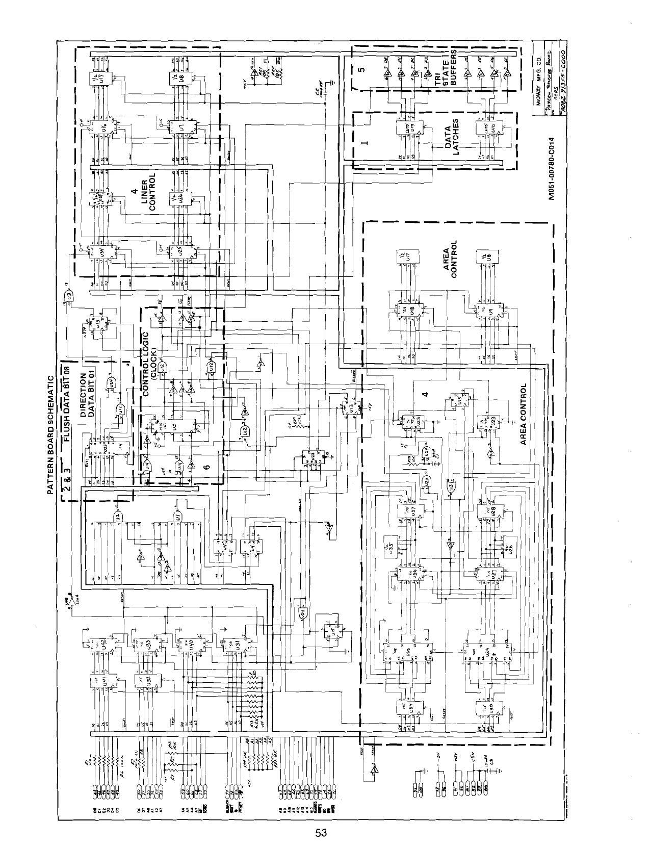
This page is a drawing, shown as the original scan.
TROUBLE SHOOTING CARD RACK SYSTEM
All test points are found on the rear side of the Back Panel Board PC A082-93006-C/ D000.
- +5VDC PINS 87 AND 88.
- +12VDC PINS 91 AND 92.
- -5VDC PINS 95 AND 96.
- LOGIC GROUND PINS 99 AND 100.
. SYSTEM CLOCK 7.1MHZ PINS 97 AND 98.
. VIDEO CLOCL 3.5MHZ PINS 93 (CHROM).
- CPU CLOCK 1.7MHZ PINS 89 AND 90.
- CPU RESET PIN 94 (NORMALLY HIGH).
- DATA BITS (0-7) PINS 44 TO 51.
- ADDRESS BITS (0-15) PINS 55 TO 70.
- COMPOSITE VIDEO PIN 85.
For all Additional Test Points refer to Page #15.
DESIGNATION
MAS 25
WATCHDOG
LIGHTPEN
VERTDR
MXD1 MXD2 MXD3 MXD4 MXDS MXD6 MXDT7 bo DL D2 D3 D4 DS D6 BACK PANEL BOARD PC A082-93006 C/ D000
DESCRIPTION PIN DESIGNATION
Screen RAM Video Load Strobe 51 DT
Write Enable 52 SCREEN
Secial Data 1 53 RMCO Serial Data 0 54 RMCL Row Address Strobe 3 55 AO Row Address Strobe 2 56 AL Row Address Strobe 1 ST Al Row Address Strobe 0 58 A3 Column Address Strobe 59 A4 Data Write Enable 60 AS Multiplexed Address Bit 61 AG Multiplexed Address Bit 62 AT Multiplexed Address Bit 63 AB Multiplexed Address Bit 64 Ag Multiplexed Address Bit 65 ALO Maltiplexed Address Bit 66 AlL Memory Data Bus Bit 67 A12 Memory Data Bus Bit 68 A13 Memory Date Bus Bit 69 Al4 Memory Data Bus Bit 10 Als Memory Data Bus Bit m1 R Memory Data Bus Bit 72 ¥ B W
onamen Memory Data Bus Bit 13 Memory Dats Bus Bit 14 Buffered Address Bit 0 15 B Buffered Address Bit 1 16 NMI Microcycle Data Bus Disable 11 10 Antomatic Reset 18 WREQ Lightpen Interrupt 79 HALT Vertical Sync 80 INT Horizontal Sync 81 +5v Microcycle Control 0 82 +5v Microcycle Control 1 83 R-¥ Read 84 B-Y Machine Opcode Cycle 85 VIDEO Microcycle Data Bus Bit 86 +2, SvREF Microcycle Data Bus Bit 87 +5¥ Microcycle Data Bus Bit 88 +5v Microcycle Data Bus Bit 89 > Microcycle Data Bas Bit 90 3 Microcycle Data Bus Bit 91 +12v Microcycle Data Bus Bit 92 +1lyv Microcycle Data Bus Bit 93 CHROMA Data Bit 94 RESET Data Bit 95 -5v Data Bit 96 -5v Data Bit 97 7M Data Bit 98 ™ Data Bit 99 GND Data Bit 100 GND
renemano onamenon
onamene DESCRIPTION Data Bit 7 Soreen RAM Decode Refresh Microcycle Coatrol 0 Refresh Microcycle Control 1 Address Bit 0 Address Bit 1 Address Bit 2 Address Bit 3 Address Bit 4 Address Bit 5 Address Bit 6 Address Bit 7 Address Bit 8 Address Bit 9 Address Bit 10 Address Bit 11 Address Bit 12 Address Bit 13 Address Bit 14 Address Bit 15 Dynamic RAM Refresh
Wait Bus Acknowledge Write . Bus Request Non-maskable Interrupt Input/Output Request Memory Request Halt CPU stopped Interrupt Request Positive 5 volt Power Supply Positive 5 volt Power Supply Red minus Video Blue minus Video Composite Video 2.5 volt Chroma Center Reference Positive 5 volt Power Supply Positive 5 volt Power Supply CPU Clock 1.7897725 Mhz Opposite phase CPU Clock 1.7891725 Mhz Positive 12 volt Power Supply Positive 12 volt Power Supply 3.519545 Mhz Chroma Subcarrier
Reset Negative 5 volt Power Supply Negative 5 volt Power Supply System Clock 7.15909 Mhz Opposite phase system clock 7.15909 Mhz System Power and Logic Ground System Power and Logic Ground
VERTOR
HORZOR
oc MCI
CUSTOM DATA
(@) Cc D oO = bp iw) oO a m (op) w
VERTDR
AIS
RFSH
Al2 AI3 CUSTOM I/0
1/0 CHIP DESCRIPTION
The Z-80 communicates with the I/O Chip through Input and Output instructions. The state of an 8 x 8 switch matrix can be read through the Switch Scan circuit. When an Input instruction is executed, one of the SO0-SO7 lines will be activated. When a line is activated, the switch matrix will feed back eight bits of data on SI0-S!7. This data is in turn fed to the Z-80 through MUXDO - MUXD7.
The Z-80 can read the position of four potentiometers (pots) through the A-D Converter circuit. The pots are continuously scanned by the A-D Converter and the results of the conversion are stored in a RAM with Input instructions.
Tne Z-80 loads data into the Music Processor with Output instructions. This data determines the characteristics of the audio that is generated.
AODRESS CHIP DESCRIPTION
THE Microcycle Decoder generates twelve bits of Z-80 address from the 8-bit Microcycle Data Bus. This address is then fed through MUX | and MUX II to MAO-5 which go to the RAM. The Scan Address Generator generates a 12-bit address which is used to read video data from the RAM. This address goes from 0 to FFFH once every frame (1/60 sec.).
MUX | sends either the Scan Address of Z-80 Address to its 12 outputs. An output of the Scan Address Generator controls MUX I. If the Scan Address Generator and the Z-80 request a memory cycle at the same time, the Scan Address Gererator will have higher priority and the Z-80 will be required to wait (by the WAIT output). The Scan Address Generator never requires the memory for more than one consecutive memory cycle, so the Z-80 is never required to wait for the memory for more than one cycle. HORIZ DR and VERT OR synchronize the Scan Address Generator with the Data Chip and the TV Scan.
The purpose of MUX {I is to multiplex its 12 inputs to the six address bits in the two time slices required for 4K x 4116 pin RAMS.
The Memory Cycle Generator controis memory cycles generated by either the Z-80 or Scan Address Generator. MREQ, RD, M1, RFSH, and A12-A15 are from the 2-80. A12-A15 are fed directly from the Z-80 because if they were brought out of the Microcycle Decoder, they would arrive too late in the memory cycle. The RASO - RAS3 outputs are used to activate memory cycle and all four RAS’s are used to control four banks of RAM (16K x 8). WRCTL and LTCHD0 are control signals to the Data Chip. WRCTL tells the Data Chip when to place data to be written to memory on the Memory Data Bus. LTCHDO tells the Data Chip when valid data from RAM is present on the Memory Data Bus.
DATA CHIP DESCRIPTION
The TV Sync Generator uses 7M and 7M (7.159090 MHZ square waves) to generate NTSC standard sync and blank to be sent to the Video Generator. It also generates HORIZ DR and VERT DR for synchronization with the Address Chip. HORIZ DR occurs once every horizontal line (63.5 usec), and VERT DR occurs once every frame (16.6 msec).
The Shift Register loads parallel data from the memory data bus (MDO - MD7) and shifts it out of its two serial outputs. The TV Sync Generator controls when data is loaded or shifted. In acommercial game SERIAL 0 and SERIAL 1 are sent through the MUX | to MUX II. The two bits from MUX i select 8 bits to be sent through MUX II to the Video Generator. These 8 bits then determine the analog values of VIDEO, R-Y, and B-Y. 2.5V is a 2.5V DC reference level.
The Clock Generator generates 0G and PX from 7M. These are the clocks for the rest of the system. The frequency of PX is half that of 7M and the frequency of 0G is half that of PX.
The Microcycle Generator generates the microcycle control bits, MCO and MC1, from IORQ, MREQ, RD, and M1, all from the Z-80.
In memory write cycles WRCTL is activated and the Memory Control circuit generates DATEN. The Magic Function Generator takes the data from the Z-80 on MUXD0 - D7 and transfers it to MDO - MD7. If a Magic write is being done, the Magic Function Generator will modify the data as required before it places it on the memory data bus.
Z-80 CPU PIN DESCRIPTION
The Z-80 CPU is packaged in an industry standard 40 pin Dual In-Line Package.
The 1/O pins are shown in figure 3.0-1 and the function of each is described below.
SYSTEM CONTROL
ADDRESS Bus
CPU CONTROL
cPU BUS CONTROL
DATA Bus
Z-80 PIN CONFIGURATION
FIGURE 3.0-1
SERVICE BULLETIN
GAME: WIZARD OF WOR
SUBJECT: NEW 6 CARD Z-80 SYSTEM USING A CARD RACK
GAME CARD (A084-90708-A961) | & OQ CUSTOM CHIP (TWO) TALKING CHIP - SC-01
ROM & RAM CARD (A084-91367-A961) RAMS 2114 ROMS 9316 OR 9332
CPU CARD (A082-91354-F000) Z80 CPU ADDRESS CUSTOM CHIP DATA CUSTOM CHIP CRYSTAL 14, 318
RAM CARD (A082-91356-C000) TWO RAM CARDS 16 RAM EACH (M4027)
PATTERN CARD (A082-91355-C000) SHIFTS INFORMATION AT A FASTER RATE
POWER SUPPLY
ANDY DUCAY SERVICE MANAGER (A082-90411-B000)
WELLS-GARDENER 19” COLOR MONITOR SCHEMATIC DIAGRAM
MOS1!- 00087-A0!!
INTERFACE BOARD P313
VERTICAL RASTER POSITION ADJUSTMENT CENTER ae up “7 DOWN anorie |
<£ MAIN BOARD MQ-29 [service th
Vosc Vose VP RE ORIV! Hise CBMO Y See00 BEcinae: R302 2 ra303 as “P30 aigiey 2548250 ecigss FSC er
HORIZONTAL RASTER POSITION ADJUSTMENT
ERROR AMP
sow L. ase, a3 a. . a |] } EMT «
tee a ; 1a asasnate HOR DRIVE BOARD [Mi
25Ci 1708 OQ) 28c1 196 25Cia34 38e i893 K4616A, K4666A— 5815
VI. T.V. MONITOR MANUAL
R301 R302 R303 R304 R305 R306 R307 R309 R310 R311 R312 R313 R314 R315 R316 R317 R319 R320 R321 R322 R323 R324 R325 R328 R330 R331 R351 R352 R353 R354 R355 R356 R357 R358 R359 R360 R361 R363 R364 R365 R366 R367 R368 R369 R370 Ra71 VR301 R302 VR351
C306
C310 C3 C312
R501 R502 R503 R504 R505 R506 R551 R501
cs01 VERT/HOR BOARD (MT/QJ)
| Description | Ref. No. | Description |
RESISTORS CAPACITORS (CONT.)
| 203X6500-628 | 820 Ohm, + 5%, | 1/8W Carbon | 6313 | 203x0025-087 | 47 UF, 50V Electrolytic | |
| 203X6500-902 | 12k Ohm, + 5%, 1/8W Carbon | C315 | 203X0015-082 | 10 uF, 25V Electrolytic | ||
| 203X6500-927 | 15k Ohm, = 5%, 1/8W Carbon | C316 | 203X1100-220 | 3300 UF, 50V, + 10% Mylar | ||
| 203X6500-886 | 10k Ohm, + 5%, 1/8W Carbon | C317 | 202X8000-616 | 100 pF, 50V, 2 10% Ceramic | ||
| 203X6501-241 | 330k Ohm, * 5%, 1/8W Carbon | C351 | 202X7000-281 | 1500 pF, 50V, * 10% Ceramic | ||
| 203X6500-645 | 1k Ohm, + 5%, 1/8W Carbon | C352 | 202X7000-247 | 1000 pF, 50V, + 10% Ceramic | ||
| 203X6500-689 | C353 | 203X1100-573 | «(0.022 UF, SOV, * 10% | Mylar | ||
| 203X6500-724 | C355 | 203X1100-858 | 0.1 uF, SOV, + 10% Mylar | |||
| 203X6501-285 | C356 | 203x0015-105 | 47 UF, 25V Electrolytic | |||
| 203X6501-065 | C357 | 203X 1201-013 | 0.015uF, 200V + 10% PP | |||
| 203X6501-126 | 100k Ohm, + 5%, 1/BW Carbon | 358 | 203X 1201-034 | 0.018 uF, 200V, + 10% | PP | |
| 203X6001-326 | 10k Ohm, * | 5%, V/8W Carbon | C359 | 203x0040-013 | 47 UF, 160V Electrolytic | |
| 203X6501-044 | 47k Ohm, = 5%, 1/8W Carbon | C360 | 202X7000-482 | 0.01 uF, SOV, + 10% Ceramic | ||
| 203X6500-628 | 820 Ohm, = 5%, 1/8W Carbon | C361 | 203X1100-509 | 0.015 uF; 50V, + 10% Mylar | ||
| 203X6500-420 | 120 Ohm, * 5%, V/8W Carbon | 6362 | 203X0025.058 | 10 uF, 50V Electrolytic | ||
| 203X6206-441 | 2.2 Ohm, | 5%, 1/2W Carbon | C363 | 203X 1205-487 | 0.01 UF, 630V, + 10% | PP |
| 203X6500-169 | 100 Ohm, = | 5%, 1/8W Carbon | C364 | 202X7000-482 | 0.01 uF, 50V, "+ 10% Ceramic |
203X6500-927 15k Ohm, = 5%, 1/8W Carbon 203X6700-509 560 Ohm, + 5%, 1/2W Carbon 203X9100-121 22. Ohm, + 5%, 2W M.O. SEMICONDUCTORS 203X6500-689 1.5K Ohm, +5%, 1/8W Carbon
| 203X6500.988 | 27k Ohm, = 5%, 1/8W Carbon | R301 | 200X4082-614 | Transistor, 2548260 | |
| 203X6500-326 | 47 Ohm, * 5%, 1/8W Carbon | TR302 | 200X317 4-006 | Transistor, 28C17400 | |
| 203X6500-628 | 820 Ohm, * 5%, 1/8W Carbon | TR303 | 200X3174-006 | Transistor, 28417400 | |
| 203X6500-886 | 10k Ohm, = 5%, 1/8W Carbon | TR304 | 200X3174-006 | Transistor, 2SC17400 | |
| 203X6501.209 | 220k Ohm, + 5%, 1/8W Carbon | TR305 | 200X4049-081 | Transistor, 2SA490YLBGLI | |
| 203X6500-724 | 2.2k Ohm, * 5%, 1/8W Carbon | TR306 | 200X3162-538 | Transistor, 28C1625YLBGLI | |
| 203X6500-927 | 15k Ohm, = 5%, 1/8W Carbon | TR307 | 200X3174.014 | Transistor, 2SC1740R | |
| 203X6500-944 | 18k Ohm, * 5%, 1/8W Carbon | TR308 | 200X3174-006 | Transistor, 28C 17400 | |
| 203X6500-783, | 3.9k Ohm, * 5%, 1/8W Carbon | TR351 | 200X4085-415, | Transistor, 2SA854Q | |
| 203X6500-902 | 12k Ohm, * 5%, /8W Carbon | R352 | 200X3172-208 | Transistor, 2801722BKS | |
| 203X6500-561 | 470 Ohm, + 5%, 1/8W Carbon | TR353 | 2003174006 | Transistor, 28017400 | |
| 203X6500-724 | 2.2k Ohm, = | 5%, 1/8W Carbon | TR354 | 200X4082-614 | Transistor, 2548260 |
| 203X6500-666 | 1.2k Ohm, * 5%, 1/8W Carbon | x301 | 201X2010-144 | Diode, (SI) 1S2473-172 | |
| 203X6501-088 | 68k Ohm, 2 5%, 1/8W Carbon | x302 | 201X2010-144 | Diode, (SI) 182473-T72 | |
| 203X5500-471 | 27 Ohm, * 5%, 1/4W Comp. | 303 | 200X€000-026 | Diode, (GE), INGOTVGL | |
| 203X6000-998 | 1.2k Ohm, = | 5%, 1/8W Carbon | X304 | 200X€010-165 | Diode (Sl) ISS81 |
| 203x6500-666 | 1.2k Ohm, = 5%, 1/8W Carbon | X305 | 201X2010-165 | Diode (Si) 1SS81 | |
| 203x9014-988 | 47k Ohm, = 5%, 1W M.O. | X306 | 201X2010-165 | Diode (SI) ISS81 | |
| 203X6700-989, | 56k Ohm, = 5%, 1/2W Carbon | 307 | 200X8010-102 | Diode (SI) MA26W | |
| 203X6001-148 | 3.3k Ohm, #5%, 1/8W Carbon | x308 | 200X€010-094 | Diode (St) 12473, | |
| 340X2222-734 | 2.2k Ohm, * 5%, 1/2W Carbon | X351 | 201X2010-144 | Diode (St) 182473-T72 | |
| 203X6500-785, | 3.9k Ohm, * 5%, 1/8W Carbon | x352 | 201X2010-144 | Diode (Si) 182473-172 | |
| 203X6500-762 | 3.3k Ohm, + | 5%, 1/4W Carbon | X353. | 201X2010-144 | Diode (Si) 1S2473-T72 |
| 302X6 100-961 | 1k Ohm, + 5%, 1/4W Carbon | X354 | 201X2010-144 | Diode (SI) 1S2473-T72 | |
| 203X6104-751 | 2.7k Ohm, * 5%, 1/4W Carbon | X355 | 200X£220-851 | Diode (Zener) RD10EB! | |
| 204X2122-083 | Varistor, 250K Ohm, Vert. Hold | X366 | 200X€100-130 | Diode (HS) RU-1 0.3 US |
204X2114-065, Varistor, 20K Ohm, Vert. Size 204X2114-059 Varistor, 50K Ohm, Hor. Hold MISCELLANEOUS
| CAPACITORS | 4301 | 204X$300-958 | Socket, 6 Pin | ||
| 1100-928 | 0.15 uF, 50V, + 10% Mylar | 4302 | 204X€300-958, | Socket, 6 Pin | |
| 303x1100573 | 0.022 uF. S0V, + 10% | Mylar | P301 | 204X9601-185 | Plug, 6 Pin |
| 203X 1100-858 | 0.1 uF, SOV, + 10% Mylar | P302 | 204x9601-195 | Plug, 6 Pin | |
| 203X0025-026 | 2.2 uF, 50V, Electrolytic | TH301 | 201x0000-534 | Thermistor |
203X1100-928 0.15 uF, 50V, + 10% Mylar 203X1100-858 0.1 uF, 50V, + 10% Mylar 203x0010-011 22 uF, 16V Electrolytic TRANSFORMERS & COILS 203X0020-099 1000 UF, 35V Electrolytic
| 202X7000-69 | 0.0082 uF, 50V, + 10% Ceramic | 13st | 201%5200-091 | Coll, Horiz. Ose. |
POWER BOARD (MV)
| 503 | 203x0010-011 | 22 uF, 16V Electrolytic | |
| RESISTORS | C551 | 203X0005-046 | 220 uF, 10V Electrolytic |
204x1725.052 180 Ohm, + 10%, 15W WW 203X6000-608 100 Ohm, + 5%, 1/8W Carbon SEMICONDUCTORS 203X6000-960 1k Ohm, + 5%, 1/8W Carbon
| 203X6000-879 | 560 Ohm, * 5%, 1/8W Carbon | TRS01 | 200X3174-006 | Transistor, 28017400 |
| 203X9014.965 | 1W M.O. | ’%TR502 | 200X3145-404 | Transistor, 2561454 |
| 203X6500-842 | 178 Carbon | TRS51 | 200X3172-305 | Transistor, 2801723 |
| 203X6500-420 | 11BW Carbon | x501 | 201X2230-042 | Diode, (SI) Zener EQB01-06V |
| 204X2050-001 | Varistor Vert. Adj | x502 | 201X2010-144 | Diode, (Si) 1S2473-T72 |
CAPACITORS MISCELLANEOUS
| 203x0040-020 | 10 UF, 160V Electrolytic | 501 | 204X9300-958 | Socket, 6 Pin |
| 202X7000-281 | 1500 pF, 50V, + 10% Ceramic | P501 | 204X9601-195 | Plug, 6 Pin |
| TH5O1 | 201X0000-618 | Thermistor |
NECK BOARD (MS/QG)
| Ref. No. | Part No. | Description _ | _ | Rel. No. | Part No. | Description |
RESISTORS
| R401 | 203Xx6500-709 | 1.8k Ohm & 5% 118W Carbon | cao | 200x7000-247 | 1000 pF, 50V, 10% Geramie | ||
| Raga | 203%6500708 | 1Bk.Chm = | Siete Carbon | C404 | 202X7110.019 | 1500 pF, 2kV' + 10% Ceramic | |
| R403 | 203X6500-709 | 4.8k Ohm + 5% | 1/8W Carbon | ae | Boer 110008 | 1600 BF 2k | 109 |
‘Ohm 2 5% EW Carbon PF, 12kV, 2 10% Ceramic
| neat | Feces cop | a | ohn | Ca | C406 | 202X7050-483 | 01 uF, 500V, | 10% | Ceramic |
| ee | poaeson aay | oe ony F eve ew Galen | 407 | 202X7110.019 | 1500 pF, 2kV + 10% | Ceramic | |||
| aor | ceexespo sce | 270 Ohm 2 5% VaW Gar | C408 | 202x8000:550 | 68 pF, SOV, = 10% Ceramic |
oe ren Y
| eed | Peateeg a0 | 0 Ota | oe, EW Carbon | C409 | 202X8000-550 | 88 pF, SCV, = 10% Ceramic | |
| ed | 20sXe200800 | amon | 8% | VEW Carbon | caro | 202XB000-550 | 68 pF, 50V, + 10% Ceramic |
| Rat0 | 203X6500-800 | 4.7% Ohm + 5% | 1/8W Carbon | ||||
| Ratt | 203X6500-800 | 4.7k Onm 2 5% 1/8W Carbon | |||||
| Ra12 | 203%9104-809 | 12k Ohm # 5% 2.0W Metal Oxide | f | uct | |||
| R413 | 203X9104-809 | 12k Ohm + 5% 20W Metal Oxide | SEMICONDUCTORS | ||||
| Rata | 203X9 104-809 | 12k Ohm x 5% 2.0W Metal Oxide | |||||
| Rais | 203X5601-313 | 27k Onm & 10% 1/2W Comp. | TRao1 | 200X3206-800 | Transistor, 2862068, 25C1514 | ||
| Rate | 203x5601-313 | 27k Ohm x 10% | 12W Comp. | (F output) | |||
| R417 | 203X5601-313, | 2.7k Ohm # 10% | 1/2W Comp. | R402 | 200%3206-800 | Transistor, 2502068, 2801514 | |
| Rate | 203%5602-254 | 470k Ohm * 10% | 1/2W Comp. | (G output) | |||
| Rag | 203X5602-185 | 330k Ohm + 10% 1/2W Gomp. | 3 | a | Bi: | ||
| R422 | 203X9105-117 | 1.0 Ohm + 10% | 2W Metal Oxide | "409 | bile | Connie sees | |
| RaZ3 | 203X5102-158 | 270k Ohm + 5% | 1/4W Carbon | ||||
| vRao1 | 204x2115.014 | 500 Ohm Varistor R Drive | Dn | opiate 28 | Diode, ig23er (protector | ||
| vrao2 | 204x2115.014 | 500 Ohm Varistor B Drive | me | gonzon | (26: | Diode tezcey hretetion | |
| vR403 | 208x2115-006 | 5k Ohm Varister R Cutoff | |||||
| vRa04 | 204X2115-006 | 5k Ohm Varistor G Cutoff | |||||
| R405 | 204X2115-006 | 5k Ohm Varistor B Cutofi | |||||
| R406 | 204x2000-025 | 1M Ohm Varistor Screen | MISCELLANEOUS | ||||
| CAPACITORS | 1401 | 206X5003-729 | Socket, 5 Pin | ||||
| J402 | 206X5003-983, | Socket, 3 Pin | |||||
| cao1 | 202X7000-247 | 1000 pF, 50V, 10% Ceramic | Paot | 208x9600-329 | Plug, 5Pin | ||
| e402 | 20247000-247 | 3000 pF, 50V, 19% Ceramic | p402 | 204X9600-254 | Plug, 3 Pin |
4* 297X2000-072 HIGH VOLTAGE ASSEMBLY (1701) FINAL ASSEMBLY PARTS
| ATT | 204X1625-058 | 3.3 Ohm, + 10% 10W WW Resistor | 4% 88X-0129:506 | 19VJTP22 Pix Tube |
| vR702 | 204X3901-125 | Focus Contro! | 38A5554-000 | Assy. Purity Shid/Degaussing |
| x701 | Diode (S! HV) | 205X8800-256 | Lateral/Purity Assembly | |
| x702 | Diode (S! HV) } Part of T701 | xk 202X1110810 | Yoke, Defiection | |
| x703 | Diode (Si HV) | 208X2000-946 | CRT Socket |
2972000072 HV Unit (1701) 6A0397 Plug, Line Cord 92753-003 Degaussing Coll (L701)
INTERFACE BOARD (P305) (MODEL 19K 4608) RESISTORS SEMICONDUCTORS
| R201 | 340X3910.934 | 1/2.W Carbon | 7R201 | 86X0121-001 | Transistor (NPN) | |
| R203 | 340X3102.934 | 1/2W Carbon | TR202 | 86X0121.001 | Transistor (NPN) | |
| R204 | 340X2101.934 | _ AW Carbon | TR203 | 86X0121-001 | Transistor (NPN) | |
| R206 | 340X3331-944 | .12W Carbon | TR204 | 86X0066-001 | Transistor (PNP) | |
| F207 | 340x3102-934 | 4/2W Carbon | R205 | ‘86X0086-001 | Transistor (PNP) | |
| R208 | 340X2152-934 | 1/4W Carbon | TR206 | 86X0066-001 | Transistor (PNP) | |
| R209 | 340X2 101-934 | 114 Carbon | TR207 | 86X0121-001 | Transistor (NNP) | |
| R210 | 340X3102.934 | ‘W2W Carbon | TR208 | 86X0121-001 | Transistor (NPN) | |
| Rait | 340X2331-934 | 4/4W Carbon | R209 | 86X0121-001 | Transistor (NPN) | |
| R212 | 340X2331-934 | 1/4W Carbon | 20201 | 66X0040-018 | Diode, Zener, 6.8v, 5%, | 0.5W |
| R213, | 340X2331-934 | 414W Carbon | zD202 | 66X0040.019 | Diode, Zener, 3.9v, 5%, 0.5W | |
| R214 | 340X2201-934 | 14 Carbon | ||||
| R215 | 3402201934 | 200 Ohm, 5%, 1/4W Carbon | ||||
| R216 | 340X2201.934 | 200 Ohm, 5%, 1/4W Carbon | MISCELLANEOUS | |||
| VR201 | 40X0590-017 | 1.5k Ohm, Black Level Control | ||||
| 201 | 204X9300-958 | Socket, 6 Pin | ||||
| 202 | 204X8300-958 | Socket, 6 Pin | ||||
| CAPACITORS | J203 | 206X5019-207 | Socket, 4 Pin | |||
| P201 | 204X9601-195 | Plug, 6 Pin | ||||
| 201 | 45X0524-038 | 1000 uF, i6V Electrolytic | P202 | 204X9601-195, | Plug, 6 Pin | |
| 203 | 204X9600-845 | Plug, 4 Pin | ||||
| P205 | 60393006 | Plug, 6 Pin |
X901 POWER DRIVE 75¢7686 902 ERROR AMP —_25C1870
x04 28cii06A, 25c1454 POWER REGULATOR po) ° " ‘Blue ont4 RED XIO1-XI03 ond XI0S VIDEO AMP. 25C454C fi XIO2.x104 ond XI06 VIDEO AMP. 25A673C
rr
| 1x301,x302,x808,x308 ewe ame Be rig eSeod or eaciess
PLE see xs08 | me RE | vom ot) | f J] x808 ean UMiTER 2sa673 Py [B04 BL aNKina
- | 28casac orticicesr
Gam —+---- — |
i. |
Aci20V 60H2/50H2 #10% o Pie NY mae err m
TER feee eae cur owe om gow —t n°" 7 rs ay fee i
x5O1 ro ay Ties, @] | ea © ta o} ==
+ - wr
Su-11334 ea MAIN PCB ASSY _
7 501 ORV XO) HOUT X70 XRAY PROTECTOR Beisd7 WE, ascesnv 380886 or 25c454C or 25ci685 28czen or 28C26IbBK Es08e9 or 250820
00-4147-04 G07-CBO Schematic Notes Unless otherwise specified Resistance: (Q) (K--KQ, MM), 1/4 (W) carbon resistor Capacitance: 1 or higher-» (pF), less than 1-> (yF) working voltage -» 50 (V) ceramic capacitor Inductance: (» H) Electrolytic Cap: Capacitance Value (y F)/working voltage (V), NP — non-polar (or bipolar) electrolytic cap. Refer to the parts list for additional component information. 2 indicates test point connection ah indicates chassis ground unless otherwise specified Hz _ indicates cycles per second For safety purposes (and continuing reliability) 4 replace all components marked with safety syrnbol with identical type.
Parts identification on circuit boards: e.g. SU1126A (R107 = R1107) $SU3030A (R113 = R3113)
REPLACEMENT PARTS LIST - ELECTROHOME 19”’ MONITOR
special characteristics important to safety. Components identified by the 4. symbol in the PARTS LIST and on the Schematic have
DO NOT degrade the safety of the set through improper servicing.
Abbreviations for Resistors and Capacitors
Resistor Capacitor
| CR | : Carbon Resistor | C Cap. |
| Comp. R | . | Composition Resistor | M Cap |
| OMR | : Oxide Metai Film Resistor | E Cap. |
| VR | : Variable Resistor | BP E Cap. |
MF R : Metal Film Resistor
| CMF R | : Coating Metal Film Resistor | MM Cap. |
| UNF R | : Nonflammable Resistor | PP Cap. |
| FR | : Fusible Resistor | MPP Cap. |
PS Cap Tan. Cap. : Ceramic Capacitor Mylar Capacitor Electrolytic Capacitor Bi-Polar (or Non-Polar) Electrolytic Capacitor : Metalized Mylar Capacitor Polypropylene Capacitor Metalized PP Capacitor Polystyrol Capacitor : Tantal Capacitor
SERVICE REPLACEMENT PARTS LIST
Symbol Description
Main P.C.B. Ass'y CRT Socket P.C.B. Ass'y Purity Shield Ass'y Part Number SU-1133A SU-3032A 07-220083-03
Outside of the P.C.B. Ass’y Symbol Description Picture Tube 19” A AXDefiection Yoke PC Magnet A 2sFlyback Transf. A ASHVR ROS UNF Resistor 220 2,25W K C04 C Capacitor 150pF, AC1.5KV x01 Si. Transistor x02 Si. Transistor sc Screw #8-3% sc Screw % x % Pix Tube Mtg. (4) WA Pyramidal Lock Washer (4) Nut Retainer, Pix Tube Mtg. (4) Clip — P.C.B. Support Standoff Wire Terminal (Gnd. Strap) Terminal Lug (Gnd.) Groundstrap Assy. Grounding Spring Wire Hook (Gnd. Strap) Purity Shield Holddown Clamp Support Brkt. RH Support Brkt. LH Chassis Base Yoke Wedge (3)
Purity Shield Ass’y. Parts List
Symbol Description Degaussing Coil D911, D912 Rectifier 1 Amp 600V (2) Pin Terminal (2) Pin Terminal Housing Purity Shield (2 pcs.) Purity Shield (2 pcs.) cot Capacitor 100nF 10% 400V R921 Resistor, Wirewound 332, 4W Fire Retardent Term. Strip 4 Lug
CRT Socket P.C.B. Ass’y (SU-3032A) Parts List
Resistors Symbol Description
| R3105 | Vv | R |
| R3106 | Vv | R 200 |
| R3113 | Vv | R 5K |
| R3114 | Vv | R SK |
| R3115, | Vv | R 5K |
| R3116 | OM | R 10KQ2W J |
| R3117 | OM | R 10KQ2W J |
| R3118 | OM | R 10K22W J |
R3119 Comp. R 3.3KQ%WK R3120 Comp. R 3.3KQ%WK C3121 Comp. R 3.3KQ%WK
Capacitors Symbol Description C3107 E Cap. 10uF 250VA C3108 C Cap. 1000pF DC1400v P
Coils Symbol Description 3101 Peaking Coit Part Number 17-7198-03 A29779-D = 21-141-01 A75034-B = 29-32-01 A29951-B A46600-A QRF258K-221 QCZ0101-005 2SD870 2SC1106A 31-610818-06 31-601418-12 33-255-01 33-494-01 33-629-02 33-670-010R-02 34-228-03 34-33-04 34-574-02 35-212-03 35-3053-02 35-2348-01 35-3890-01 35-3890-02 38-449-02 39-1233-01
Part Number 21-1007-30 28-22-27 34-708-01 34-709-01 35-3847-01 35-3847-02 48-171544-62 42-113301-03 34-492-09
Part. Number QVZ3234-022 QVZ3234-022 QVZ3234-053 QVZ3234-053 QVZ3234-053 QRG029J-103 QRG029J-103 QRG029J-103 QRZ0039-332 QRZ0039-332 QRZ0039-332
Part Number QEWS53EA-106 QCZ9001-102M
Part Number QQL043K-101
Semiconductors Symbol X3101 X3102 X3103
Miscellaneous Symbol A Description Si. Transistor Si. Transistor Si. Transistor
Description ASCRT Socket
Main PCB Ass’y (SU-1133A) Parts List
Resistors Symbol R1406 R1408 R1410 R1414 R1415, R1421 R1422 AFR1401 AR1503 R1504 R1509 R1512 R1514 R1515 R1522 R1523 R1528 R1534 VR1501 AR1703 A\R1704 ANR1901 R1902 R1903 R1904 R1905 4Q1908 AR1909 R1910 ANFR1901
Capacitors Symbol C1301 1402 C1407 C1411 C1412 C1508 Ac1512 AC1513 AC1514 C1515 1520 1523 1524 AC1531 AC1532 C1904 C1905 Descripti Vv Vv CMF OM OM OM v AF A\CMF Vv OM OM OM CMF CMF OM OM ZN ZN A\CMF A\CMF A\Posistor UNF CMF OM om AXCMF Vv AMF AF R DDDVDVDVVDD DVVVVDVDV DVD VDDVDVVVVVVID tion 2002 2002 6.821W J 3.3K Q1W J 2.7K Q1W J 12KQ2W J 10KQ 6822W K 11.8KQ.4W +1% 5KQ 10K22W J 8.2KQ2W J 82022W J 8.201W J 4701W J 68 22W J 39021W J
392%2W +1% 7.68KQ. AW +1%
2Q7WK 4.703W J 10KQ2W J 18K 21W J AT QW +1% 2KQ 2.74K QW +1% 2202'2W K
Description BPE Tan. E E E PP Na APP APP PP BPE E M ZXPP APP Cap. Cap. Cap. Cap. Cap. Cap. Cap. Cap. Cap. Cap. Cap. Cap. Cap. Cap. Cap. Cap. Cap. 3.3uF 50V A 2.2uF 16V K 4.7uF 6.3V A 100uF 160V A 3.3uF 160V A 5600uF 50V J 2000pF DC1500V J 2000pF DC1500V J 2000pF DC1500V J 0.53uF DC1200V J 3.3uF 50V A 1uF 160V A 0.1uF 200V K 2000pF DC1500V J 1500pF DC1500V J
10uF 250V A Part Number 28C1514VC 2SC1514VC 2SC1514VC
Part Number A76068
Part Number QVZ3230-002 QVZ3230-002 QRX019J-6R8 QRG019J-332 QRGO019J-272 QRGO026J-123Z QVZ3230-014 QRHO024K-680M QRV142F-1182 QVZ3230-053 QRGO26J-103Z QRG026J-822Z QRGO26J-821Z QRX019J-8R2 QRX019J-4R7 QRG026J-680Z QRG019J-391 ERZ-C05ZK471 ERZ-CO5DK271 QRV122F-3902 QRV142F-7681 A75414 QRFO76K-2RO QRX039J-4R7 QRG026J-103Z QRGO019J-183 QRV122F-470Z QVPSA0B-023E QRV142F-2741 QRH124K-221M
Part Number QEN61HA-335Z, QEES1CK-2258 QEWS51JA-475, QEW52CA-107 QEW52CA-335 QFP31HJ-562 QFZ0082-202 QFZ0082-202 QFZ0082-202 QFZ0067-534 QEN61HA-335Z2 QEW62CA-105Z QFM720K-104M QFZ0082-202 QFZ0082-152 QEY0034-001 QEWS2EA-106
Coils Symbol L1502 L1503 L1504
Transtormers Symbol T1501 T1503
Semiconductors Symbol 1C1501
X1101 X1102 X1103 X1104 X1105 X1106 X1301 X1302 X1303 X1304 X1305 X1401 X1402 X1501 X1901 x1902
D1101 D1102 D1103 D1301 D1401 D1402
D1503 D1504 D1505 D1506 D1507 D1508 Ap1701 A\D1901 AD1902 A\D1903 A\D1904 A\D1905
Miscellaneous Symbol AF 1901 A\F1902 Description Linarity Coil Width Coil Heater Choke
Description Hor. Drive Transf. Side Pin Transf.
Description IC
Si. Si. Si. Si. Si. Si. Si. Si. Si. Si. Si. Si. Si. Si. Si. Si.
Si. Si. Si. Si. Si. Transistor Transistor Transistor Transistor Transistor Transistor Transistor Transistor Transistor Transistor Transistor Transistor Transistor Transistor Transistor Transistor
Diode Diode Diode Diode Diode Zener Diode
Si. Si. Diode Diode Zener Diode Si. Si. Si. Diode Diode Diode AZener Diode ASi. ASi. ASi. ASi. Diode Diode Diode Diode AZener Diode
Description AFuse 1.254 AUL Fuse 3A Part Number A39835 C30380-A C30445-A
Part Number A46022-BM C39050-A
Part Number HA11244
2SC1685(R) 2SA673(C) 2SC1685(R) 2SA673(C) 2SC1685(R) 2SA673(C) 2SC1685(R) 2SC1685(R) 2SA673(C) 2SC1685(R) 2SC1685(R) 2SD478 2SD478 2SC2610BK 2SC2688 (K.L.M.) 2SC1890A (E.F.) wo6A WO6A WO6A 1SZ473H 1$Z473H RD10F(C) HF-1 VO9E RD11E(B) WO6A 18S81 18Z473H RD20Ev2 1$1887A 1$1887A 1$1887A 1S1887A RD6.8EV3
Part Number QMF53U1-1R25S, QMF66U1-3ROS
ts Ut XIOL X10 ond XI05 VIDEO AMP 25C454C o 261685, A X102.xi04 ond x106 VIOEO_AMP_2SA673C To noh mas peo vr —_—_—_—_—_—_—_—_—_— 25cz6I! or 2scisia a
crt SOCKET eee! [pce Assy | | a |
303 BEAM LIMITER 252673 + Pxg04 avankine 2scasac
x30a7
\COl POWER REGULATOR ons SU-1103A MAIN PCB ASSY
1402, x01, x402
Schematic Notes Unless otherwise specified Resistance: (Q) (K*KQ, MMQ), 1/4 (W) carbon resistor Capacitance: 1 or higher—» (pF), less than 1 (yF) working voltage» 50 (V) ceramic capacitor Inductance: (v H)
- Electrolytic Cap: Capacitance Value (yF)/working voltage (V), & X701 XRAY PROTECTOR WOLHOWYE oscoamy fobede ey eae sone . NP > non-polar (or bipolar) electrolytic cap. a en) bite BEE oc AE 28C26Il or 2Scz610BK 250869 Refer to the parts list for additional component information. acig0v goms/sont 2 indicates test point connection oh indicates chassis ground unless otherwise specified Hz indicates cycles per second For safety purposes (and continuing reliability) a replace all components marked with safety symbol with identical type.
G07-FBO Parts identification on circuit boards: 00-4147-03. e.g. SU1126A (R107 = R1107) SU3030A (R113 = R3113)
REPLACEMENT PARTS LIST - ELECTROHOME 13”’ MONITOR
Components identified by the A symbol in the PARTS LIST and on the Schematic have special characteristics important to safety. DO NOT degrade the safety of the set through improper servicing.
Abbreviations for Resistors and Capacitors
Resistor Capacitor
| CR | : Carbon Resistor | C Cap. |
| Comp. R | : Composition Resistor | M Cap |
| OM R | : Oxide Metal Film Resistor | E Cap. |
| VR | : Variable Resistor | BP E Cap. |
MF R : Metal Film Resistor CMF R Coating Metal Film Resistor MM Cap.
| UNF R | : Nonflammable Resistor | PP Cap. |
| FR | : Fusible Resistor | MPP Cap. |
PS Cap Tan. Cap. : Ceramic Capacitor Mylar Capacitor Electrolytic Capacitor Bi-Polar (or Non-Polar) Electrolytic Capacitor Metalized Mylar Capacitor Polypropylene Capacitor Metalized PP Capacitor Polystyrol Capacitor : Tantal Capacitor
Symbol
Outside of the P.C.B. Ass’y Symbol Avo1 AXDY01
ARN AROS Aco4a xo1 1co1 Lo1
BR BR sc WA
CH Description Main P.C.B. Ass'y CRT Socket P.C.B. Ass'y
Description APicture Tube A\Deflection Yoke PC Magnet Wedge AFlyback Transf. AsFocus V R UNF Resistor 22052, 25W. K ANC Capacitor 150 pF, AC1.SKV Si. Transistor IC Regulator Degausing Coil Degausing Coil Pin Terminal (2) Degausing Coil Pin Terminal Housing Groundstrap Ass'y. Groundstrap Wire Terminal Groundstrap Spring (2) Support Bracket RH Support Bracket LH SCREW 10-% Pix Tube Mtg. (4) Pyramidal Lockwasher (4) Clip P.C.B. Support (2) Ground Lug Chassis Base Part Number SU-1103A SU-3016A
Part Number 370ESB22(E) C29123-V A7T6366-A 30006 A19183-A A46606-A QRF258K-221 QCZ0101-005 2SD869 STR383 21-1007-31 34-708-01 34-709-01 34-697-04 34-228-03 35-3560-01 35-3919-01 35-3919-02 31-631018-08 33-255-01 33-629-02 34-33-04 38-452-01
Main P.C.B. Ass’y (SU-1103A) Parts List
Resistors Symbol R1406 R1408 R1410 R1414 R1415 R1421 R1422 AXFR1401 2XR1503 R1504 R1509 R1511 R1514 R1515 R1522 R1523 R1528 R1534 VR1501 AXR1703 AXR1704 AXR1901 R1902 R1903 R1904 ASFR1901 Capacitors Symbol C1402 C1411 C1412 C1508 C1511 AxC1512 AC1513 AC1514 C1515 1520 C1524 C1904 C1905 A\C1907
Coils Symbol L1501 L1502 L1503 L1504 L1901
Transformers Symbol 71501 T1503 Description Vv Vv R R CMF R OM OM OM Vv AF R R R R R ASCMF R Vv OM OM OM R R R R CMF R CMF R OM OM ZN ZN R R R R ACMF R ASCMF R AsPosistor UNF R CMF R OM AF R R 2002 2002 6.821W J 3.3KQ 1W J 2.7KQ1W J 12KQ2W J 10KQ 6822W K 11.8KQY“W +1% 5KQ 1OKQ2W J S.6KQ2W J 68022 2W J 8.221W J 4.701W J 5622W J 3902 1W J
39K QW +1% 7.68K QW +1%
2Q7W K 5.623W J 1OKQ2W J 2202%2W K
Description Tan. E E PP E ANPP App App PP. BPE M E E AMM Cap. Cap. Cap. Cap. Cap. Cap. Cap. Cap. Cap. Cap. Cap. 2.2uF 16V K 100uF 160V A 3.3uF 160V A S5600pF 50V J 47uF 160V A 2000pF DC1500V J 2000pF DC1500V J 2500pF DC1500V J 0.53uF DC1200V K tuF 50V A 0.1uF 200V K Cap. Cap. Cap. 10uF 250V A 0.1uF AC150V Z
Description Peaking Coil Liniarty Coil Width Coil Heater Choke Line Filter
Description Hor. Drive Transf. Side Pin Transf. Part Number QVZ3230-022 QVZ3230-022 QRX019J-6R8 QRGO019J-332 QRGO019J-272 QRG029J-123 QVZ3224-014H QRH024K-680M QRV142F-1182 QVZ3230-053 QRGO029J-103 QRGO29J-562 QRGO029J-681 QRX019J-8R2 QRX019J-4R7 ORG029J-560 ORGO19J-391 ERZ-C05ZK471 ERZ-COSDK271 QRV122F-3902 QRV142F-7681 A75414 QRFO76K-2RO QRX039J-5R6 QRGO26J-103Z QRH124K-221M
Part Number
QEES1CK-225B QEWS2CA-107 QEWS2CA-335 QFP31HJ-562 QEWS2CA-476S, QFZ0082-202 QFZ0082-202 QFZ0082-252 QFZ0067-534 QEN61HA-105Z QFM72DK-682M QEY0034-001 QEWS2EA-106 QFZ9008-104
Part Number A75360-6 A39934 C30380-A C30333-A, A39475-J
Part Number A46022-BM C39050-A,
Semiconductors Symbol 101501
X1101 x1102 X1103 X1104 X1105 X1106 X1301 X1302 X1303 X1304 X1305 x1401 x1402 X1501 x1701 D1101 D1102 D1103 01301 01401 D1402 D1503 01504 D1505 D1506 D1507 01508 4xD1701 4\D1901 4xD1902 A\D1903 4801904
Miscellaneous Symbol AF1901 AF 1902 Description ILC.
Si. Si. Si. Si. Si. Si. Si. Si. Si. Si. Si. Si. Si Si. Si. Si. Si. Si. Si. Si. Transistor Transistor Transistor Transistor Transistor Transistor Transistor Transistor Transistor Transistor Transistor Transistor Transistor Transistor Transistor Diode Diode Diode Diode Diode Zener Diode Si Si |. Diode |. Diode Zener Diode Si Si Si . Diode . Diode . Diode A\Zener Diode ASi ASi ASi ASi Diode |. Diode . Diode |. Diode
Description AsFuse 1A ANUL Fuse 3A Part Number HA11244
2SC1685(R) 2SA673(C) 2SC1685(R) 2SA673(C) 2SC1685(R) 2SA673(C) 2SC1685(R) 2SC1685(R) 2SA673(C) 2SC1685(R) 2SC1685(R) 20478 20478 2SC26108K 2SC1685(P-S) Wo6A WO6A WO6A 182473H 1S2473H RD10F(C) HF-1 VOsE RD11E(B) WO6A 18881 182473H RO20EV2 181887A 1S1887A 181887A 1$1887A
Part Number QMF53U1-1ROS QMF66U1-3ROS
CRT Socket P.C.B. Ass'y (SU-3016A) Parts List
Resistors Symbol 3105 R3106 R3113 R3114 R318 R3116 R3117 R3118 R3119 3120 3121
Capacitors Symbol 3107 C3108,
Coils Symbol 13101
Semiconductors Symbol X3101 X3102 X3103
Miscellaneous Symbol A Description 2002 2002 5KQ 5KQ. 5KQ 10K N2W J OK Q2W J OM R 10K22W J Comp. R 3.3K2%W K Comp. R 3.3K2%W K Comp. R 3.3K2%W K OO<<<<< DUDDDDD IM IM
Description E Cap. 10uF 250V A C Cap. 1000pF DC1400V P
Description Peaking coil
Description Si. Transistor Si. Transistor Si. Transistor
Description A\CRT Socket Part Number QVZ3234-022 QVZ3234-022 QVZ3234-053 QVZ3234-053 QVZ3234-053 QRG029J-103 QRGO29J-103 QRG029J-103 QRZ0039-332 QRZ0039-332 QRZ0039-332
Part Number QEWS2EA-106 QCZ9001-102M
Part Number QQL043K-101
Part Number 2SC2611 2SC2611 2S8C2611
Part Number A75522
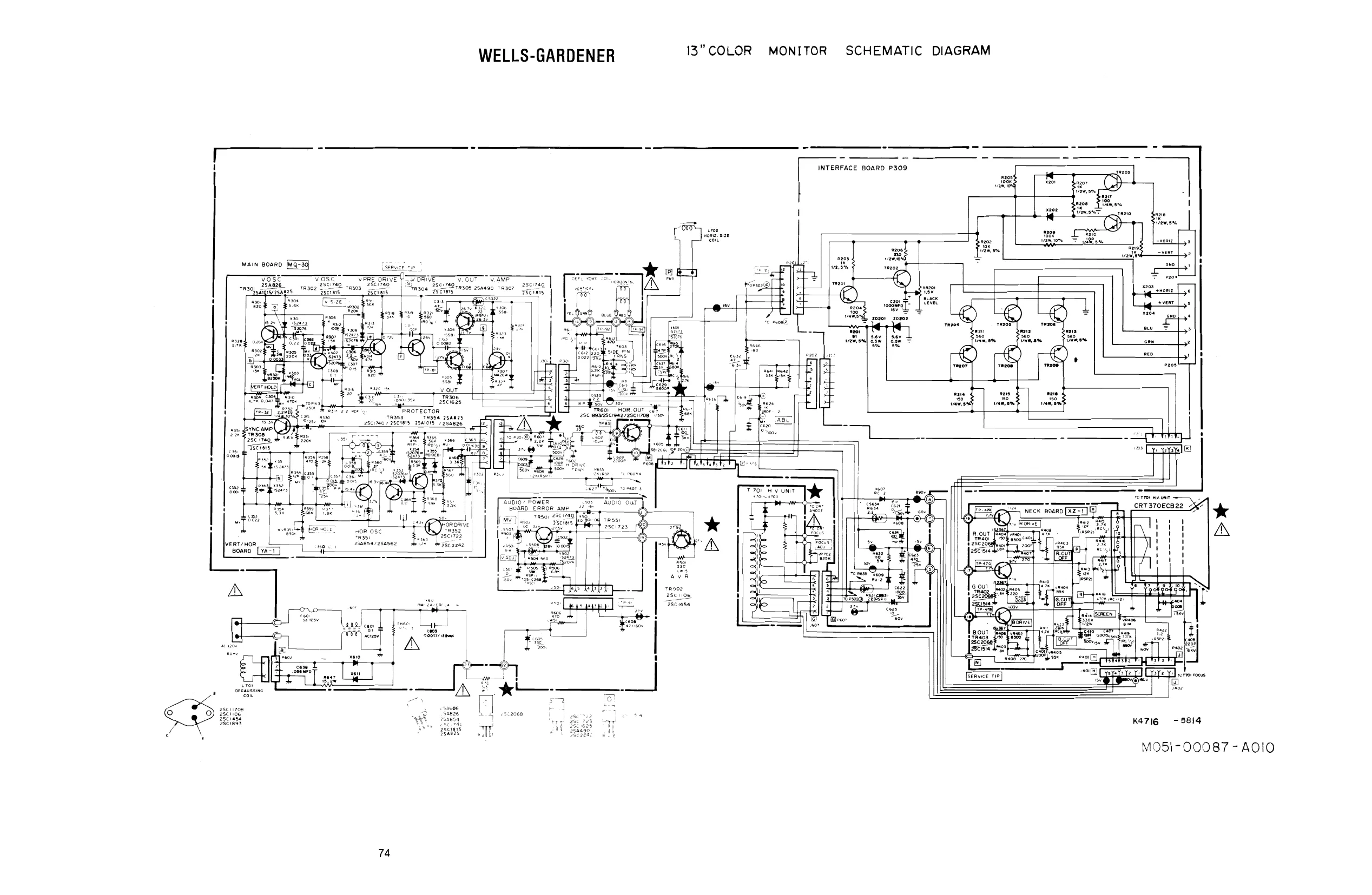
This page is a drawing, shown as the original scan.
WELLS-GARDENER
INSTALLATION AND SERVICE INSTRUCTIONS
COLOR PURITY AND VERTICAL CENTERING ADJUSTMENT
For best results, it is recommended that the purity adjustment be made in the final monitor location. If the monitor will be moved, perform this adjustment with it facing west or east. The monitor must have been operating 15 minutes prior to this procedure and the faceplate of the CRT must be at room temperature. The monitor is equipped with an automatic degaussing circuit. However, if the CRT shadow mask has become excessively magnetized, it may be necessary to degauss it with manual coil. Do not switch the coil OFF while the raster shows any effect from the coil. Purity Magnets are used for Color Purity and V Centering Adjustment. Purity Adjustment procedure is as follows.
- Remove R-G-B signal from monitor.
- Turn Green Cut off Controi (VR404) on the Neck Board fully CCW. Turn Red and Blue Cut off Control (VR405) fully CW.
- Pull the Deflection Yoke backward so that the Magenta belt will appear. (See Fig. 4) 4, Move the two Purity Magnets and bring the Magenta belt to the mechanical center of the screen (See Fig.
- The vertical center position should be set VRS to —5/64” (—2 mm) as shown in Fig. 6. Insert service tip "N" on Neck circuit board to "S” on Vert./Horiz. circuit board (See Fig. 13). To check, use the Green raster at low intensity. Be sure to return the service tips to their original positions for the next check. 5, Push the Deflection Yoke forward gradually and fix it at the place where the Magenta screen becomes uniform throughout.
- Turn Cut off Control, and Drive Control and confirm that each color is uniform.
- If the color is not uniform, re-adjust it moving Purity Magnets slightly.
- Move a pair of Purity Magnets at the same time (do not change the angle of the pair), and adjust the vert. center to center of screen. 9 Obtain the three colors and confirm whether white uniformity is balanced.
- Insert the temporary wedge as shown in Fig. 5 and adjust the angle of Deflection Yoke.
STATIC CONVERGENCE ADJUSTMENT
Arecently developed Deflection Yoke and Electron Guns construction has been used on this equipment in combination with In-Line Guns and Black Stripe Screen to make a barrel-type magnetic-field distribution for vertical deflection and a pin-cushion-type magnetic field for horizontal deflection with which a_ self-converging system can be obtained. This type is different from conventional unity-magnetic field distribution type deflection yoke. 4-Pole Magnets and 6-Pole Magnets are employed for static convergence instead of a Convergence Yoke.
- A cross hatch signa) should be connected to the moniter.
- A pair of 4-Pole Convergence Magnets are provided and adjusted to converge the blue and red beams. When the Pole opens to the left and right 45° symmetrically, the magnetic field maximizes. Red and blue beams move to the left and right oppositely (See Fig. 7-a and 7-b). Variation of the angle between the tabs adjusts the convergence of red and blue vertical lines. When the both 4-Pole Convergence Magnet Tabs are rotated as a pair, the convergence of the red and blue horizontal lines is adjusted.
- A pair of 6-Pole Convergence Magnets are also provided and adjusted to converge the magenta (red + blue) to green beams. When the Pole opens to the left and right 30° symmetrically, the magnetic field is maximized. Red and blue beams both move to the left and right (See Fig. 8c and 8-d). Variation of the opening angle adjusts the convergence of magenta to green vertical lines. When both 6-Pole Convergence Magnet Tabs are rotated as a pair the convergence of magenta to green horizontal lines is adjusted.
PRECISE ADJUSTMENT OF DYNAMIC CONVERGENCE (See Fig. 10 and 11)
1, Feed a cross hatch signal to the monitor.
- insert the temporary wedge and fix Deflection Yoke So as to obtain the best circumference convergence (See Fig. 10 and 11).
- Tilting the angle of the yoke up and down adjusts the crossover of both vertical and horizontal red and blue lines. See Fig. 10 (a) and (b).
- Tilting the angle of the yoke sideways adjusts the parallel convergence of both horizontal and vertical lines at the edges of the screen. See Fig. 11-a and b.
- Use three rubber wedges (thick and thin rubber wedges are used for a purpose).
- The angle of each rubber wedges are shown in Fig. 9.
- After three rubber wedges have been inserted, pull out the temporary wedge.
- Fix the rubber wedges with chloroprene rubber adhesive.
INSTALLATION AND SERVICE INSTRUCTIONS
BLACK AND WHITE TRACKING (With R/G.B. inputs grounded) 4.
- Set Black Level Control (VR201) to mid point. 5.
- Set Red and Blue Drive Controls (VR401 & VR402) to their mechanical center.
- Set the G2 Screen Control (VR406) and the 3 Cut-off Controls (VR403, VR404, & VR405) to minimum
Magenta
FIGURE 4
Temporary Wedge
a Lo FIGURES
—s ~ ts ee Green Beam foam
FIGURE &
FIGURE 9 ee aOR NX NN
A —8 cat fips a a
- es Insert Rubber Weige
cAT oY
FIGURE 10 (CCW). Slowly turn up G2 screen control until the first faint color appears. Slowly turn up the other two color cut-off controls in turn to match the first. Remove ground from R/G/B/ inputs. Adjust Red and Biue Drive Controls (VR401 & VR402) for white screen.
4-Pole Magnets and the Movement of Beams FIGURE7
Insert Rubber Wedge from Lower Side 6-Pole Magnets and the Movement of Beams FIGURE 8
ee yoo
ov BIcIr|
(insert Pubes Werge CRT Screen (trom Lett Side
cat L
oY
lalcle
Insert Rubber Wedge CRT Screen 1) ‘from Lower Side
FIGURE 11
ELECTROHOME MONITOR - GENERAL INSTRUCTIONS
Service Set-Up Procedure
The degaussing effect is confined to the picture tube since the coils are mounted on the ferrous tube shield. Shouldany part of the chassis or cabinet become magnetized, it will be necessary to degauss the affected area by means of a manual degaussing coil. Move the coil slowly around the CRT face area, then slowly withdraw for a distance of six feet before disconnecting the coil from the AC power supply Normally little, if any adjustment should be necessary. However, when a picture tube, yoke or similar component is replaced, preliminary static convergence should be done before attempting purity adjustment, and so on Set up should be done in a north/south direction. Horizontal and vertical centering taps should be set to the centre position if a major component has been changed. 1.0 Purity 1.1 Loosen yoke retaining clamp (figure 2}, remove adhesive material fixing wedges to CRT. Remove wedges completely and clean off dried adhesive from picture tube and wedges.
1.2. Asmail quantity of “nail polish” has been used to lock the purity convergence rings in place. This seal must be broken with a sharp tipped instrument before any adjustments are attempted. Some models also use a locking ring at either end of the purity and convergence rings. This must be loosened before adjustments are made. It goes without saying that upon completion of al! adjustments, the lock must be reset and/or a dab of paint or nail polish must be reapplied to edge of rings to prevent movement. 1.3. Connect an appropriate signal source, eg: Electrohome RGB generator producting a white field plus individual red, green and blue fields.
1.4 Bring the long and short purity tab protrusions in line with each other to obtain near-zero magnetic field (figure 4) (In some cases bring the flat and indented tabs together to obtain zero field). Protrusions can then be vertical, horizontal or at any convenientangle to start.
1.5 Turn off the green and blue fields and adjust setup controls to produce a red field. (See fig. 3) 1.6 Pull the deflection yoke back so that a red band appears in the centre of the screen
1.7 Spread the tabs apart as littie as necessary and rotate both rings together to center the red band horizontally on the face of the CRT (approximate). (See Fig. 5) 1.8 Slide the yoke towards the bell of the picture tube slowly to obtain a uniform red field (pure in color) across the entire tube face. Juggle back and forth slightly as necessary. Lightly tighten yoke retaining clamp. 1.9 Momentarily switch on across-hatch signal and rotate yoke to level the pattern on the face of CRT. 1.10 Return generator to regain red raster. 1.11. Turn off red field and check for pure field for each of
the green and blue fields. Reposition yoke if necessary
to obtain optimum purity on all fields. 1.12 Tighten yoke retaining clamp to prevent yoke shift or rotation. (Do not install wedges at this time.) [ro Siar sont
Figure 2
CRT SOCKET P.C.B.
sercen ve fad)
e) | sue cvrore ve oreen ove | | once curorr va reo one | Ql] Th | seo cutorr va
BE CAREFUL OF “RB” AND "B BOOST VOLTAGES PRESENT OM R.C.B Figure 3
[REAR VIEW]
Long and thort protrusions Short and long protrusiont
Let the protrusions come in fine, Figure 4
Centre Being the green band to the centre, Figure 5
2.2
2.6
2.8
3.0
3.2
3.3
3.4
3.5 Static and Dynamic Convergence
Switch generator to the crosshatch pattern. Adjust convergence around the edges of the picture tube by tilting the yoke up-down and left-right, and temporarily install one wedge at the top of the yoke or in a more optimum position. (Figures 8, 9, 10) Turn off green input and turn on the red and blue input Rotate the 4-pole (middle) pair of magnets as a unit to minimize separation of the red and blue crosshatch lines around the center of the screen (Figure 6). Variation of the angle between the tabs adjusts convergence of red and blue. (Tilt yoke as required to converge red and blue at the edges as in 2.3 above.)
Turn on green input to obtain magenta (red/blue) and green crosshatch lines. Rotate the 6-pole (rear) pair of magnets as a unit to minimize separation of the magenta and green lines (figure 7). Vary angle between the two tabs and further rotate as a unit to finalize.
When converence of 3 colors is optimized (static in center and dynamic around edges) apply stripe of paint or nail polish to converence magnet rings to prevent movement. If applicable, tighten locking ring carefully. Remove temporary wedge from yoke. Tilt yoke in updown and left-right direction for best circumference convergence and install 3 wedges. (It is best to use 3 new wedges since they have adhesive backing. Simply pull off tape, slide wedge in place and press outer flap down firmly. For more permanency apply small quantity of silastic or similar material at junction of wedges and picture tube. Do not disturb while material is setting. (Order wedges by part number 39-1233-01).
White Balance (Grey Scale Tracking) Refer to figure 3. Do the following in subdued light:
Lat the red and blue lines come in line by turning two 4 pole magnate Figure 6
[FRONT VIEW]
Magenta
Let the green and magenta lines come in line by turning two 6-pole magnets Figure 7
[REAR VIEW)
Roughly adjust the circumferential con vergence and instal! one wedge temporarily Figure 8
[FRONT VIEW] Ried Green Biye
Blue Green Red Tilting the yoke uoword will move the lines 2s shown with the sow Figure 9
(FRONT VIEW) Greer Biue
Tilting the yoke fo the right will move the lines as shown with the arrows,
Figure 10
3.6
3.7 Adjust the red and green drive controls for “neutral white” on high white picture areas. Generally these controls will be left at mech. centre.
[REAR VIEW) Anode cap
4.0
5.0
6.0 Power Supply The regulated +B1 control (R909) has been factory adjusted and normally requires no adjustment. However, if any repairs have been made to the chassis it is recommended that this adjustment should be made.
- Allow 5 minutes to warm up.
- No signal applied
- Connect an accurate D.C. voltmeter to TP-91 or the emitter of X04 power regulator transistor
- Adjust R909 for 120V. (See fig. 1)
Focus
Adjust focus control for best overall definition and picture detail an average signal applied. (Highlights should be favoured.)
Color Service Generator for G07 Monitor Electrohome has developed a color service generator that is specifically designed for use with the GO7 color data monitor. it provides the monitor with both horizontal and vertical sync, as well as the following test patterns: 1) 2) 3) Fine cross-hatch pattern Broad bar cross-hatch pattern Complete field Three color selection switches, red, green and blue, provide the ability to display the above patterns in the three primary colors as well as the three secondary colors This product may be ordered from: Contracts Marketing ELECTROHOME Electronics Wellington St. North Kitchener, Ontario Canada N2G 4J6 Telephone: (519) 744-7111, Ext. 567 X-Ray Emission Check Assure the power supply B1 is properly adjusted to 120V DC, See item 4.0 (page 8) Assure that the anode voltage does not exceed max. as per Item 2.0 page 4.
Assure that the high voltage hold down circuit is operating correctly. Use the following procedure.
- Increase the B1 greater than 138.5V by shorting collector/emitter of the power regulator, X04.
- Observe that the anode voltage (EHT) goes to 0. If the EHT does not go to 0, a fault must be located and repaired
- Remove short and set should return to normal operation. (Note, after the short is removed some monitors may not restart. In this case, remove power from monitor momentarily and normal operation will be restored.
$39 Kohn w 01 We uzoLe: OO-O-OO?
te son HaLi2uu Aw 2scus ie eee 7.08 Koon ners KK
Gor Mor WOH6 6.7 Kohn |
8.0
8.1
8.2 Circuit Diagram and Description of High Voltage Hold Down or Safety Circuit
Circuit Diagram of High Voltage Hold Down Circuit.
Operation of High Voltage Hold Down Circuit. The high voltage hold-down circuit protects the high voltage circuit from dangerous voltage with short circuiting between emitter and collector of power regulating transistor. The base voltage of X701 is increased when the B1 voltage is increased more than 138.5 V DC.
When the base of X701 is increased, a short is produced by X701 between pin 11 and ground of IC 501, shutting down the horizontal osc. and high voltage
This page carries no recoverable text. It is a drawing or a photograph. See the original scan.
H
axe ty
1 |
a
NOTES n+ spam
wost-cosers009 WIZARD OF WOR MINI
This page carries no recoverable text. It is a drawing or a photograph. See the original scan.
COMPONENT NO. A14F A15E IN4004 2N3055 M317 79M05 LM339 SG3532 470 UF, 16V. 4,700 UF, 25V. 10,000 UF, 35VDC 20,000 UF, 16VDC 20,000 UF, 35VDC MIDWAY PART NO. 0064-168XX-XXGX 0064-169XX-XXGX 0064-030XX-XXCP 0065-085XX-XXGX 0066-004BX-XXAX 0066-801 AX-XXCX 0066-020BX-XXCX 0066-044BX-XXGX 0061-271DX-5FGX 0061-314EX-5E2X 0061-322GX-5E2X 0061-326DX-5E2X 0061-300GX-5E2X
QUANTITY
(3 PER.) (6 PER.) (4 PER)
DO NOT SCALE WG. COMMERCIAL CARD RA SUPPLY K [=e | MIDWAY MFG. Co. | S 2000 MF 25V ELEC. AX, 4+ 79M05
MO5|-00789-CO2O0 -—2 oe TOMF2: ELEC. V) 470 MF I6V | AX. { 0) eo a SASF
20000 MF 16V ELEC, AX, HEAT SINK 0068 045xx ABOX ja) IN) (5 Pin] 1OO0O MF 35¥ ELEC. AX. AlaF Alar)
VETTE
This page reads as a drawing: its text was drawn rather than typeset, and comes out in fragments. See the original scan.
Vil. SCHEMATICS AND WIRING DIAGRAMS
a! Je Kk-100-F 9 / Gx (ike Cr) + (emer Cx) «7 + 2k }e3 (72K) we za) en i MN
& N
= +
az
MO5I-00873~-BO29 a MIDWAY MFG. CO. —— ne RGB IVER EAE A082 -91363ee ina comm LD Ghee 000
| COMPONENT DESIGNATION | COMPONENT NO. | MIDWAY PART NO. |
| (U1) | TBA530 | 0066-033XX-XX9X |
| (DL1-DL2) | 270NS DELAY | 0069-166XX-XAMX |
| (Q1) | 2N4401 | 0065-213XX-XXCX |
vipeo Cir > TBA-530
KEY
MO51-.00873-B030
NONE NareRAL
laeew :29 MIDWAY MFG. CO
ne
TINTA RGB INTERFACE
Cone Comes [1-5-7 Pep re. ccRS we 9082-91363 -B000
| Liat. Se GL TOA TEE Blas
COMPONENT SIDE
%a,|MIDWAY MFG. CO. vauttealas 24 ¢ mses _|
Maral reef ALDI Brag EE | [or joBd 90907 -A 76)
COMPONENT DESIGN COMPONENT NO.
(CR1-CR2) IN4004 (Q1-02) 2N4403 (Q3-04) TIP-31 (Q5) LM383 MIDWAY PART NO.
0064-030XX-XXCP- 0065-215XX-XXGX 0065-485XX-XXQX 0066-043DX-XXAX
+e
+e at OL % = I faoon SURI AUDIO I #1 Re 0 ae @ AVOIO COMMON ~~ | 294908 TIP 3/ = = Led F324 /W a FUSIBLE
KEY CED
+e
is SPR AP AUDIO it” #2 = a4es hr m3 3 Sea
MUOIG IN 4
a?
SPRRYF
COMPONENT DESIGNATION
(U1-U16) (U17-U20) (U18-U19) (U21-U22) COMPONENT NO.
14027-3 74LS166 741.253 7414 MIDWAY PART NO.
0066-228XE-XXDX 0066-206AX-XXCX 0066-583AX-XXCX 0066-520XX-XXAX aguvog WY
0009-9S¢16-280V LOOD-68L00~-ISOW se Im
vIT, U20 Lsiee!
st imt
- C= 18 ay
(3)-C = .imt RAAA-— = -AAA—a3 WAM SAA La AA ae A A lL) ROMA A=
| 1 | —e | te | —t |
qe tt
4 "
Se
LJ
ee
re al
| m | 0 | ws |
| LJ | LJ | LI |
| 1€ | ¢ | —-¢ |
| re | ry | rm] |
| us | un | us |
LI wu
| omy | 1 | AG | se |
| ry | R2 | 83 | a |
yee. Man R5= 220,—— yee re
| ye | um | U22=08 | ws |
se se se R6 —RI3 = IK
(8)- cz Imf
ule Ulg = 4027
(4)- C= Imf
(4)-C= Imf
(4)- C= Imt
- - C= mf
RI-R4= 110 ()-c=s mt
U2leLSi4
Doe
CEED— BUFAO Caa=D— BuFAI (CAIs — DATEN
> SERO/SERI
+5
a st aD ™
IK
31 O.lmtd CAPACITORS (BP) NOT SHOWN 90 moe tts é A082 — 91356 -C000 MOSI- 00789 -CO02
RAM BOARD
This page reads as a drawing: its text was drawn rather than typeset, and comes out in fragments. See the original scan.
This page reads as a drawing: its text was drawn rather than typeset, and comes out in fragments. See the original scan.
This page reads as a drawing: its text was drawn rather than typeset, and comes out in fragments. See the original scan.
z joos
Lo 10k
“£7 fn Ze
esis [ a] Uy
¥
MOSLO0789-CO14 g |memy oo | MIDWAY MFG. Co. baer fr Paréen Teaseee Bored Cees, - '"AOB2Z-9/355 -COOO *T@80 Abpen
U10 74LS133 0066-061AX-XXDX COMPONENT DESIGNATION COMPONENT NO. MIDWAY PART NO.
U11, U12, U13, U14 74LS138 0066-068AX-XXHX U15 74LS241 0066-464AX-XXHX ust 74LS02 0066-463XX-XXRX OR U2, U3, U4, US 74LS08 0066-493XX-XXCX
74.8244 0066-467AX-XXHX OR U16 14078 0066-301XX-XXDX 74LS32 0066-611XX-XXCX X21 TO X28 2114UCB 0066-131XB-XAAX U6, U7 74LS30 0066-603XX-XXHX U8 74LS32 0066-611XX-XXCX 74LS74 0066-823XX-XXCX
aD En avene,
ub) Ae viz ALS 138
TALS 32 |
as
aausos
¢—— Tass ca Pica ans | fs gy K2 X3 | X4 | XS
mone | 72 o" 4eS0%
MIDWAY MFG. CO.
A082 -W397 ~Anrer i {
i
4/44 -O1
This page reads as a drawing: its text was drawn rather than typeset, and comes out in fragments. See the original scan.
= *
| \ | (e398 | y 745398 | C war) | 745998) | Lo | a) [3 |
| 8 (ut | J 8) Cue | ‘I fp. Pus | _4| xz | & |
Pw zea = Gi cst 2K] ki , wear Ge eles Ty *
| tT Geae Goce (x) P20 | ~ | x3 |
| S) | zones (Jes (Bere | Sg 3h |
eoayee GG) )ce (Be) Ree 1 Be
| GAME BOARD | Gales Der Bales | ' | § | ||
| a | Gear GA | (Zz \ eee | 1 Us | ||
| COMPONENT DESIGNATION | COMPONENT NO. | MIDWAY PART NO. | i | Ex Ge eaar | | |
y grea] Ke «fas (ERK) RCo
| U1, U2, U3, UB | 14539 | 0066-336XX-XXDX | ' | Gar GDe Gxinr | |||||
| U4 | LM368 | 0066-034BX-XXAX | a | Geaeo Geo Eze |) @ | . yb | ula) Pune ure ‘| Lse#] | |||
| Us | 74LS153 | 0066-141AX-XXHX | WY [p Been Gey Ezxi\rer | arg hhh Ota | » © we | BS cues | J | ||
| U6 | 14099 | 0066-311XX-XXEX | ‘ | sealer Cree (izes | IMME | ||||
| rt) | TALS174 | 0066-243AX-XXBX | gales Ges Bzzee | ae BIG BG | |||||
| u10 | 74LS86 | 0066-883XX-XXDX | SS Sit Be | é | |||||
| U11, U12, U18, U19 | 74LS164 | 0066-196AX-XXDX | Gees Cec cao Ce | ne | Of | sie | ise | ||
| u13 | 74LS30 | 0086-603XX-XXHX | Gaaer Ce | . Jb. | 8) uo | 8 use | i B puee | § | |
| UIs Ue | maLsi6t | 0068. 183AK KKH | eee, Cen gatas | | : | |||||
| 5 | = | -) | a | Renee or nN | “ | ||||
| u20 | 74L$257 | 0066-643AX-XXDX | Bag as @) & pa | F | |||||
| U21, U23 | 74LS04 | 0066-473XX-XXAX | ~ ua a RE 3 aS | y | |||||
| U24 | 74LS367 | 0086-700AX-XXBX | = | ee Bove | cH esiet) fa , us7e fp i324 | e | |||||
| Q5, Q6, Q7 | TIP 110 | 0065-491 XX-XXGX | savor | 2, | 9 Cus | un | B eu | ue2 | LS |
| xt | scot | 0066-001XX-XAHX | - | ||||||
| X2, X3 | CUSTOM 1/0 | 0086-117XX-XXYX | N | OVOHO | r |
sym
| e a 8 t peo ee eve | g & i) 8 8 | a | _ ma | fe |
| aR» 4) Nato! | Lsi | “ss | 7 Ey | |
| 4 | aCe gce sce ia: | ©, | ||
| £3530 | L£5/64% | XTX) PX] Bet | ||
| 4 | (@2) | 3 | ||
| 22s. | a | aeege | @ | |
| FICRRECIRIERCIE, | ises71 RIMES | zi |
ale dae 84 LS Bluse “*°7"| TEES, 88.3, Lg Re
OXIXZ,X2 DEWorTES . SOCKETED FosirrodS
1o5I-b AB 9-02 | Dave latlniy laaweiates 27 [Png ale | MIDWAY MFG. CO.
| 9 | fe | : | z | —* aR |
| [ soey sopoe - A96/ | ARE | ae ; | AOBF- 90708 - AHo/ |
MOS!) '961- AC29 [=P [ow MIDWAY MFG. “Wi2ARD oF woe GAME BD. "cease Faced-70700-An7__| a39 oe