PlayStation 2 SCPH-50000 Series Service Manual (2nd Edition) [GH-026]
PlayStation 2 (Sony, 2000) · Service Manual · 26 pages · 2 sections · original scan
SCPH-50000 series
SERVICE MANUAL 2nd edition for GH-026 BOARD (I-chassis)
PDF created with FinePrint pdfFactory trial version http://www.fineprint.com
SAFETY CHECK-OUT
After correcting the original service problem, perform the following safety checks before releasing the set to the customer: 1.Check the area of your repair for unsoldered or poorly-sol-dered connection. Check the entire board surface for solder splashes a nd Bridge. 2.Check the interboard wiring to ensure that no wires are “pinched” or contact high-wattage resistors. 3.Look for unauthorized replacement parts, particularly transistors, that were installed during a previous repair. Point them out to the customer and recommend their replacement. 4.Look for parts which, through functioning, show obvious signs of deterioration. Point them out to the customer and recommend their replacement. 5.Check the line cord for cracks and abrasion. Recommend the replacement of my such line cord to the customer. 6.Check the B+ voltage to see it is at the values specified. LEAKAGE TEST The AC leakage from any exposed metal part to earth ground and from all exposed metal parts to any exposed metal part having a return to chassis, must not exceed 0.5 mA (500 microampers.). Leakage current can be measured by any one of three methods. 1.A commercial leakage tester, such as the Simpson 229 or RCA WT -540A . Follow the manufacturers‘ instructions to use these instruments. 2.A battery-operated AC milliammeter. The Data Precision 245 digital multimeter is suitable for the job. 3.Measuring the voltage drop across a resistor by means of a VO M or battery-operated AC voltmeter. The “limit” indication is 0.75V, so analog meters must have an accurate low-voltage scale. The Simpson 250 and Sanwa SH-63 Trd are examples of a passive VOM that is suitable. Nearly all battery operated digital multimeters that have a 2V AC range are suitable.(See Fig.A) 7.Check the metal trim, ” metallized”knobs,screws,and all other exposed metal parts for AC leakage. Check leakage as described below.
WARNINGII WHEN SERVICING, DO NOT APPROACH THE LASER EXIT WITH THE EYE TOO CLOSELY. IN CASE IT IS NECESARRY TO CONFIRM SAFETY-RELATED COMPONENT WARNINGII LASER BEAM EMISSION, BE SURE TO OBSERVE FROM A DISTANCE COMPONENTS IDENTIFIED BY MARK OF MORE THAN 25 cm FROM THE SURFACE OF THE OBJECTIVE LENS
ON THE OPTICAL PICK-UP BLOCK. LINE WITH MARK OR DOTTED
ON THE SCHMEATIC DIAGRAMS
AND IN THE PARTS LIST ARE CRITICAL TO SAFE OPERATION. REPLACE THESE COM PONENTS WITH SONY PARTS WHOSE PART NUMBERS APPEAR AS SHOWN IN THIS MANUAL .OR IN SUPPLEMENTS PUBLISHED BY SONY.
PDF created with FinePrint pdfFactory trial version http://www.fineprint.com
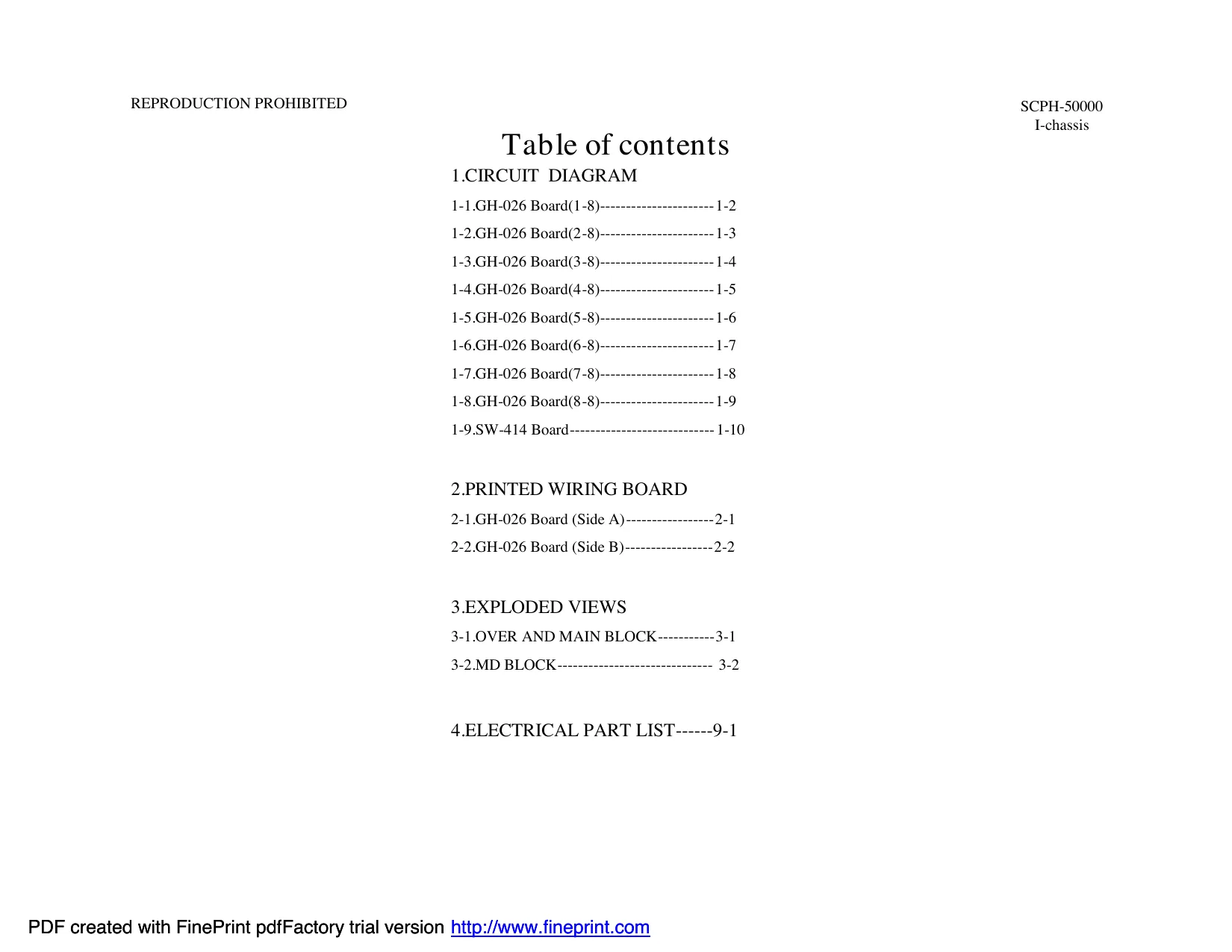
This page is a drawing, shown as the original scan.
SECTION1
CIRCUIT DIAGRAM
Note on Circuit Diagrams
• All capacitors are in μF unless otherwise noted. pF:μμF 50WV or less are not indicated except for electrolytics and tantalums •All resistors are in Ω and ¼ W or lesss unless otherwise specified • % :indicates tolerance
and tantalums.
specified.
- % :indicates tolerance.
The components identified by mark
or dotted line with mark for safety. are critical
Replace only with part number specified.
1-1 PDF created with FinePrint pdfFactory trial version http://www.fineprint.com
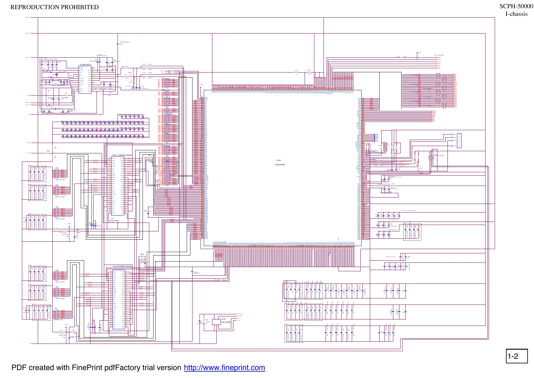
This page is a drawing, shown as the original scan.
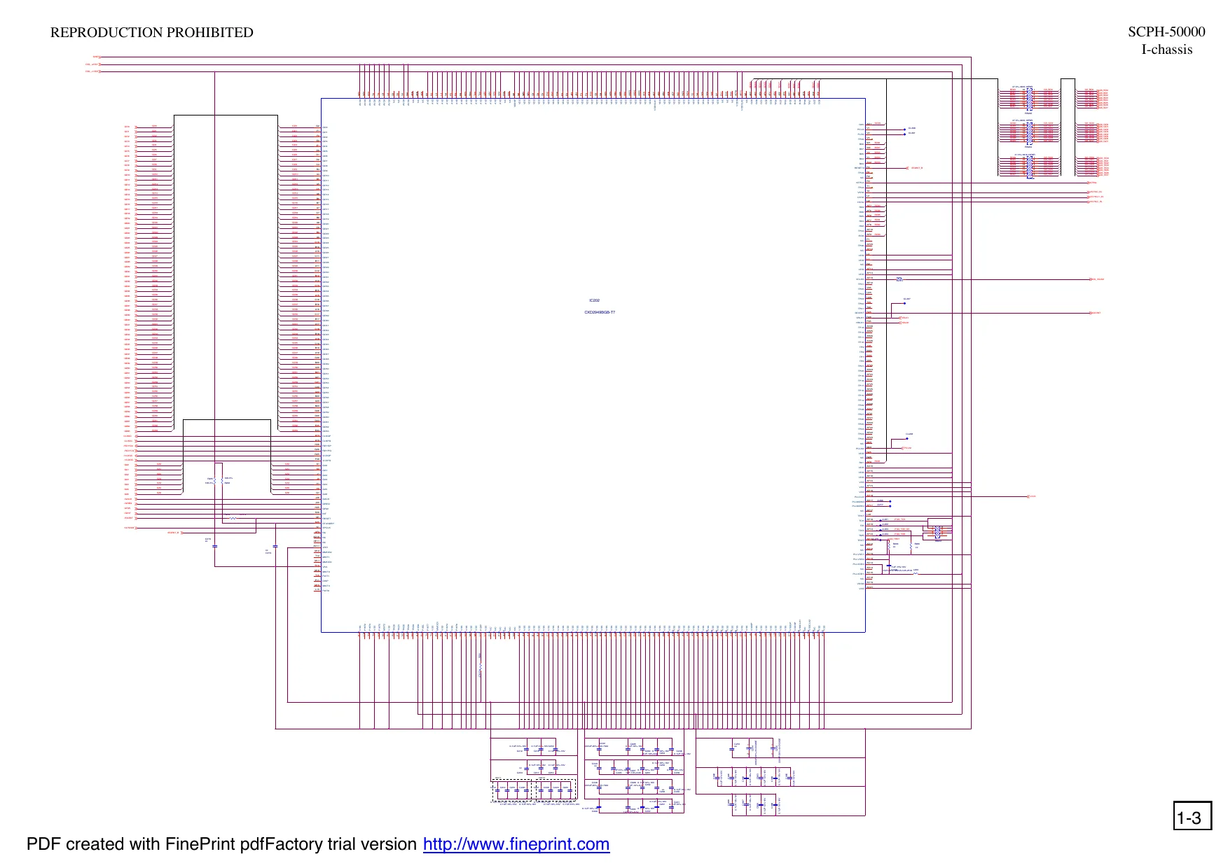
This page is a drawing, shown as the original scan.
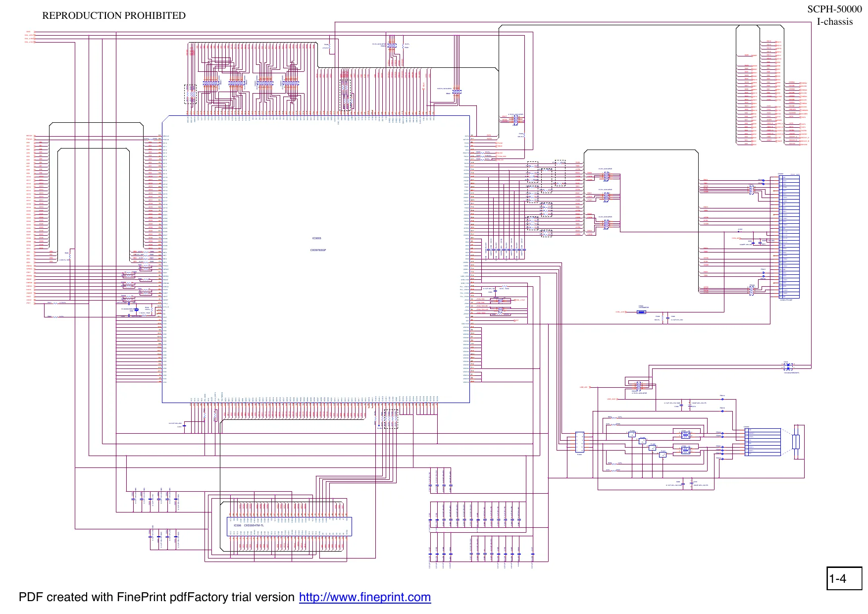
This page is a drawing, shown as the original scan.
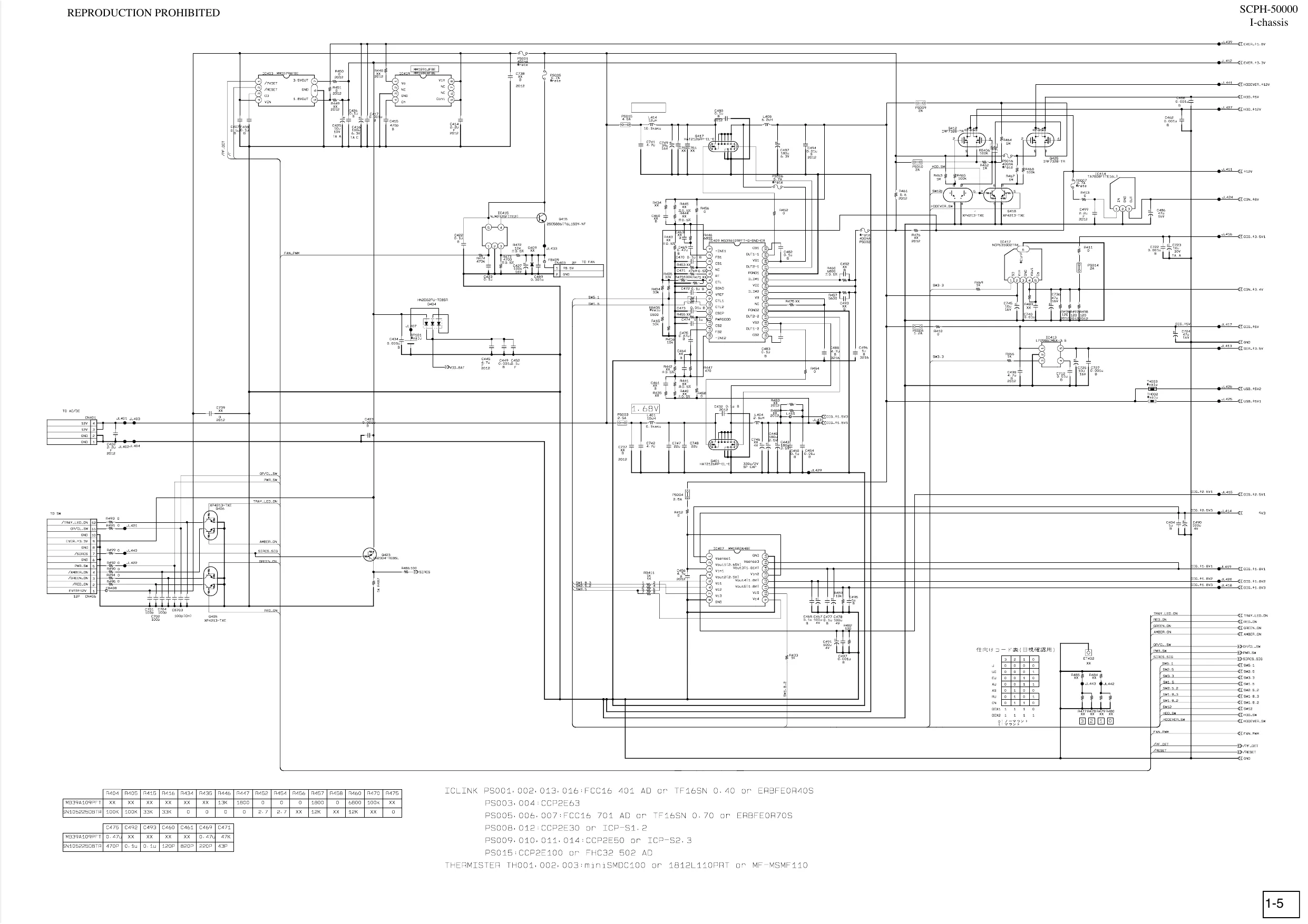
This page is a drawing, shown as the original scan.
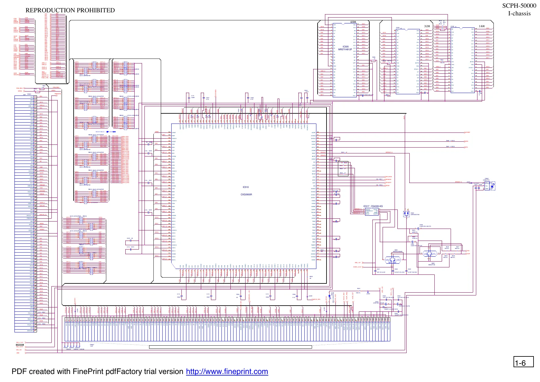
This page is a drawing, shown as the original scan.
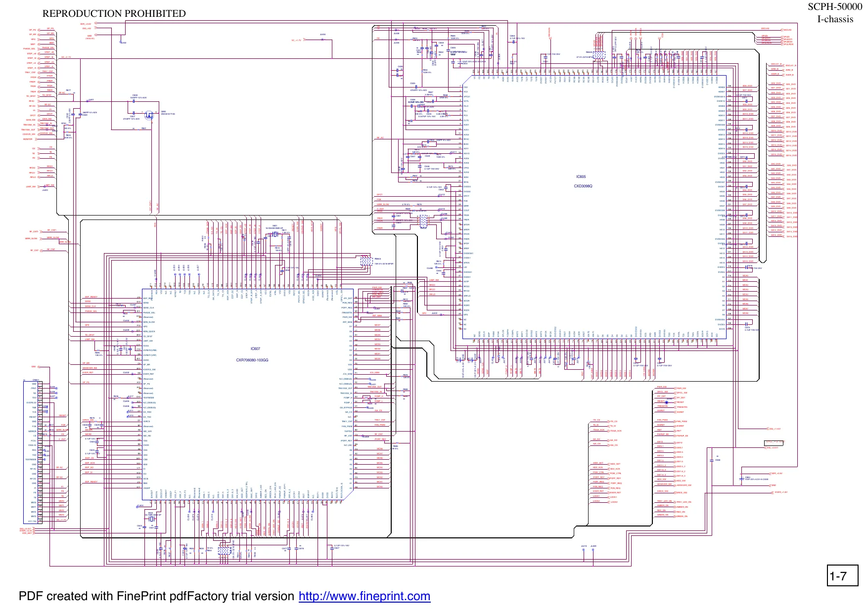
This page is a drawing, shown as the original scan.
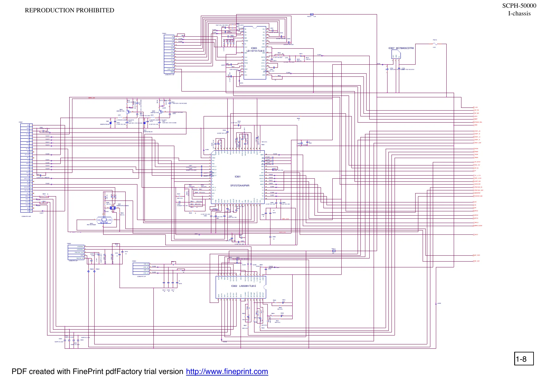
This page is a drawing, shown as the original scan.
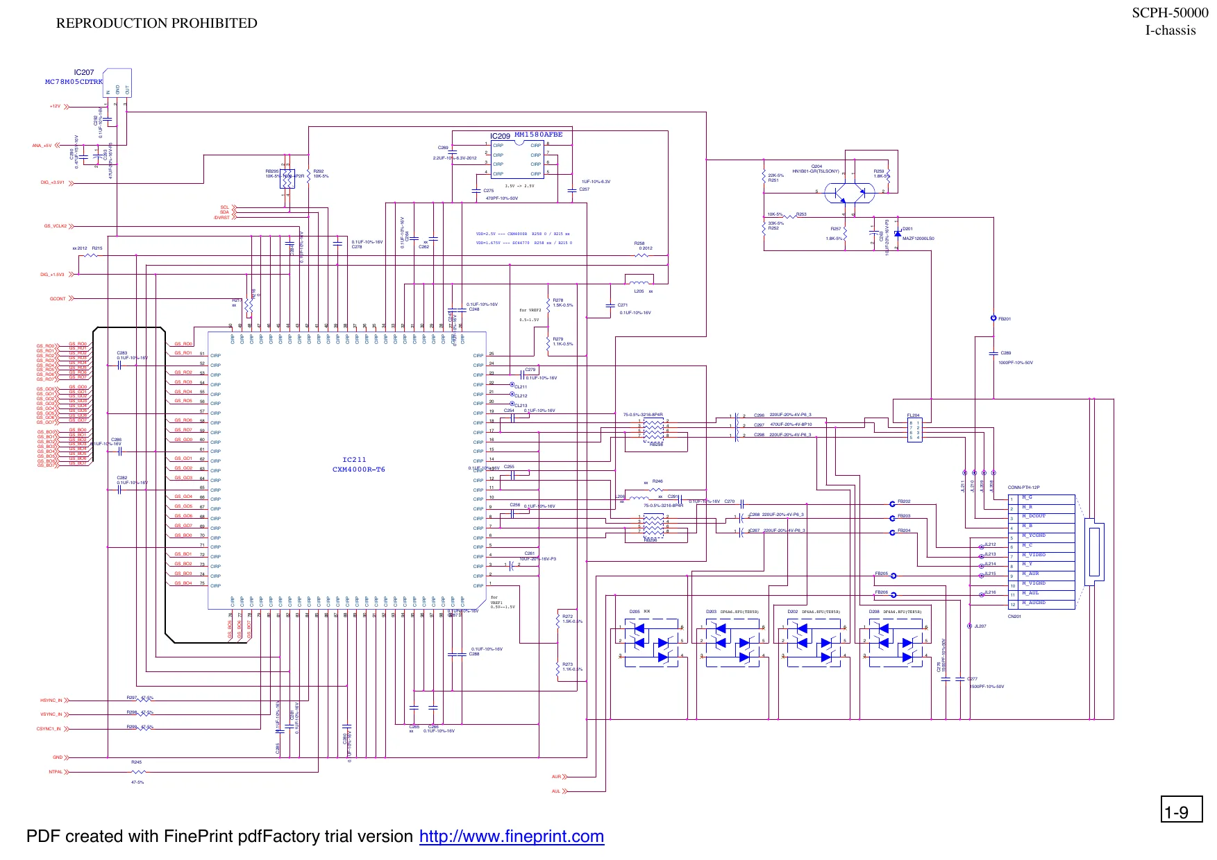
This page is a drawing, shown as the original scan.
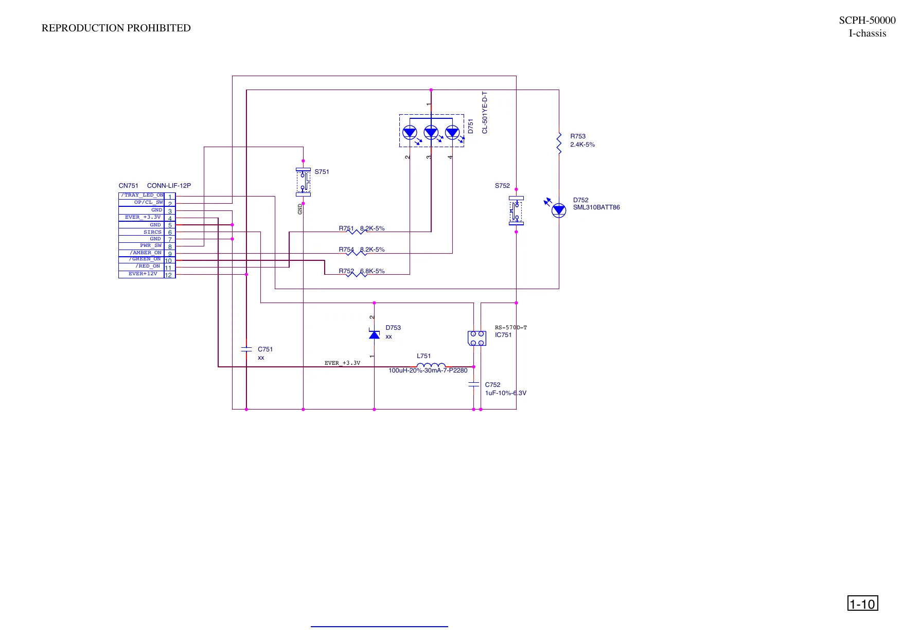
This page is a drawing, shown as the original scan.
2-2.GH -026 BOARD (SIDE A)
GH-026 BOARD (SIDE A)
2-1
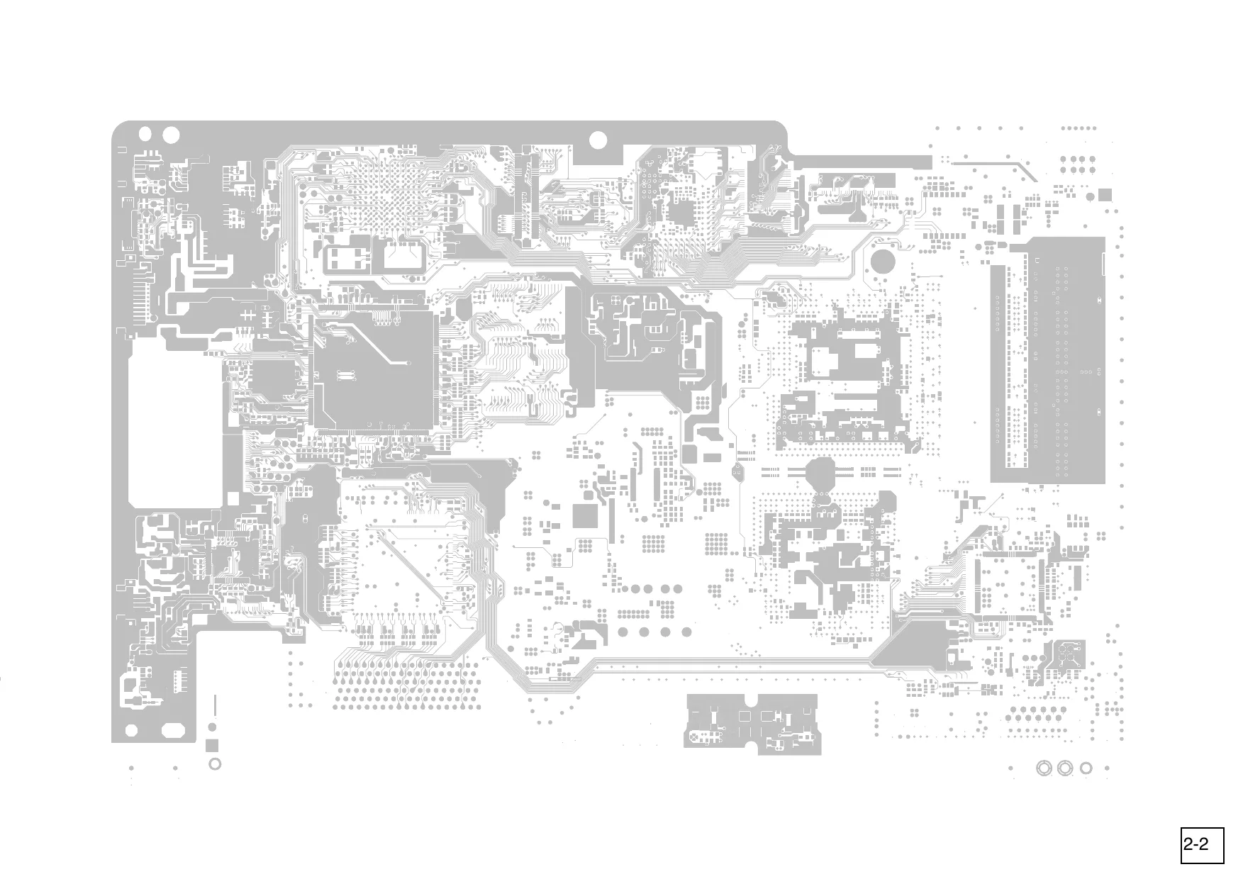
This page is a drawing, shown as the original scan.
OVERALL AND MAIN BLOCK EXPLODED VIEWS
The components identified by mark or dotted line with mark.. are critical for safety. Replace only with part number specified.
OVERALL AND MAIN BLOCK
Ref-No.
BV312
BV312
GH026 Part No. Description 1-468-758-31 1-468-758-41 1-468-759-21 1-468-760-11 1-694-873-11 1-694-874-12 1-694-875-13 1-694-875-21 1-757-934-11 1-757-934-21 1-757-934-31 1-757-934-42 1-757-934-51 1-757-934-61 1-787-009-11 1-787-035-11 1-787-036-11 POWER BLOCK POWER BLOCK POWER BLOCK POWER BLOCK TERMINAL BOARD (FRONT) TERMINAL BOARD (FRONT) TERMINAL BOARD (FRONT) TERMINAL BOARD (FRONT) CABLE, FLEXIBLE FLAT (FFC-011) CABLE, FLEXIBLE FLAT (FFC-011) CABLE, FLEXIBLE FLAT (FFC-011) CABLE, FLEXIBLE FLAT (FFC-011) CABLE, FLEXIBLE FLAT (FFC-011) CABLE, FLEXIBLE FLAT (FFC-011) DC. FAN DC. FAN DC. FAN
1-786-345-51 1-786-209-31 3-084-513-01 3-084-506-01 3-088-455-01 3-088-253-01 3-074-548-01 3-074-549-01 3-074-553-01 3-074-555-01 3-074-555-11 3-084-521-01 3-074-556-01 3-084-509-01 3-060-400-01 3-074-557-01 3-074-558-01 A-6801-026-A SWITCH, POWER (WITH AC INLET) SWITCH, POWER (WITH AC INLET) SHIELD HDD (H) PANEL(H), REAR SHIELD B (I) LABEL, MODEL NUMBER(I) COVER, SCREW CAP TITE (CZN), M3X6 +BV S SCREW, +BV TAPPING SCREW, +BV TAPPING SCREW(M3X27) SCREW, BRAZIER HEAD P TIGHT BUTTON, SWITCH(H) TAPPING (B2X6.5) TAPE, VOID
BV312
P360 BV312 M316 M327 M354
A-6801-138-A
P360
M327 GH026 A-6801-139-A A-6801-140-A A-6801-141-A A-6800-396-A X-3953-585-1 X-3954-056-1 X-3953-586-1 X-3953-587-1 3-074-550-01 M316
M354
3-1
MD BLOCK
Ref-No.
MF6
MF2 MF5
MF3
MF1 MF4
MF9
3-2
SECTION4
ELECTRICAL PART LIST
NOTE:
•Due to standardization , replacements in the parts list may be different form the parts specified in the diagrams or the components used on the set. •RESISTORS METAL :Metal-film resistor. F: nonflammable •SEMICONDUCTORS In each case , u:μ ,for example: uA..:μA.. uPA..: μPA.. uPB..: μPB.. uPC..: μPC.. uPD..: μPD.. •CAPACITORS uF:μF •COILS uH:μH
When indicating parts by reference number. please include the board.
The components identified by mark
or dotted line with mark for safety. are critical
Replace only with part number specified.
•SC Classification S: Supplied parts U: Unsupplied parts
4-1 PDF created with FinePrint pdfFactory trial version http://www.fineprint.com
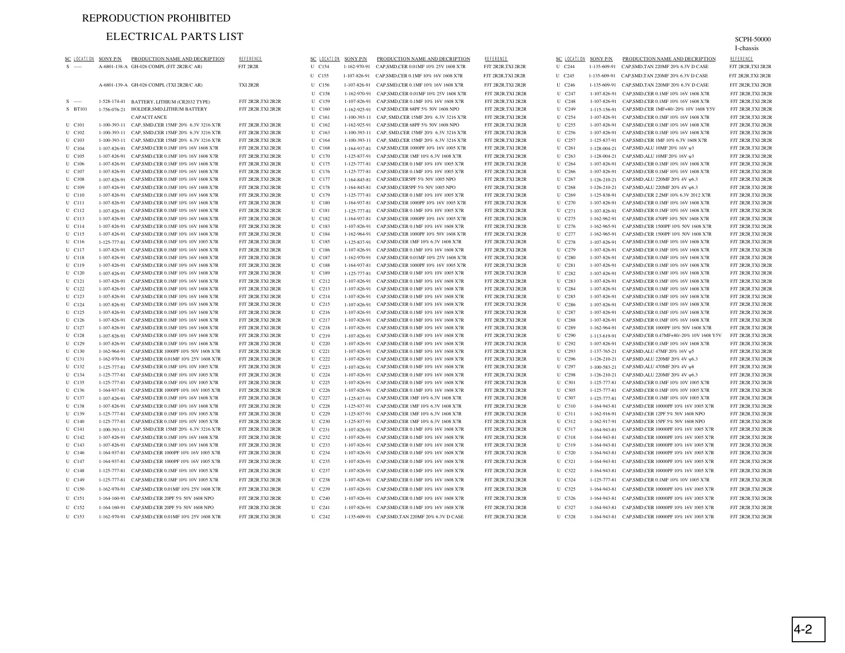
This page is a drawing, shown as the original scan.
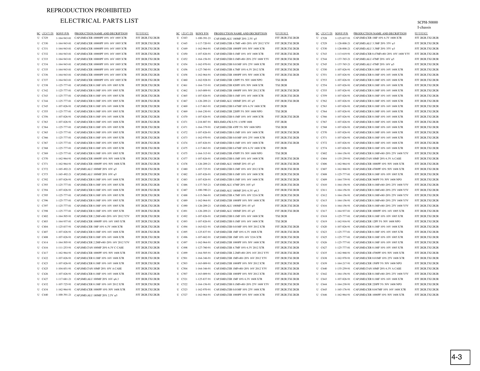
This page is a drawing, shown as the original scan.
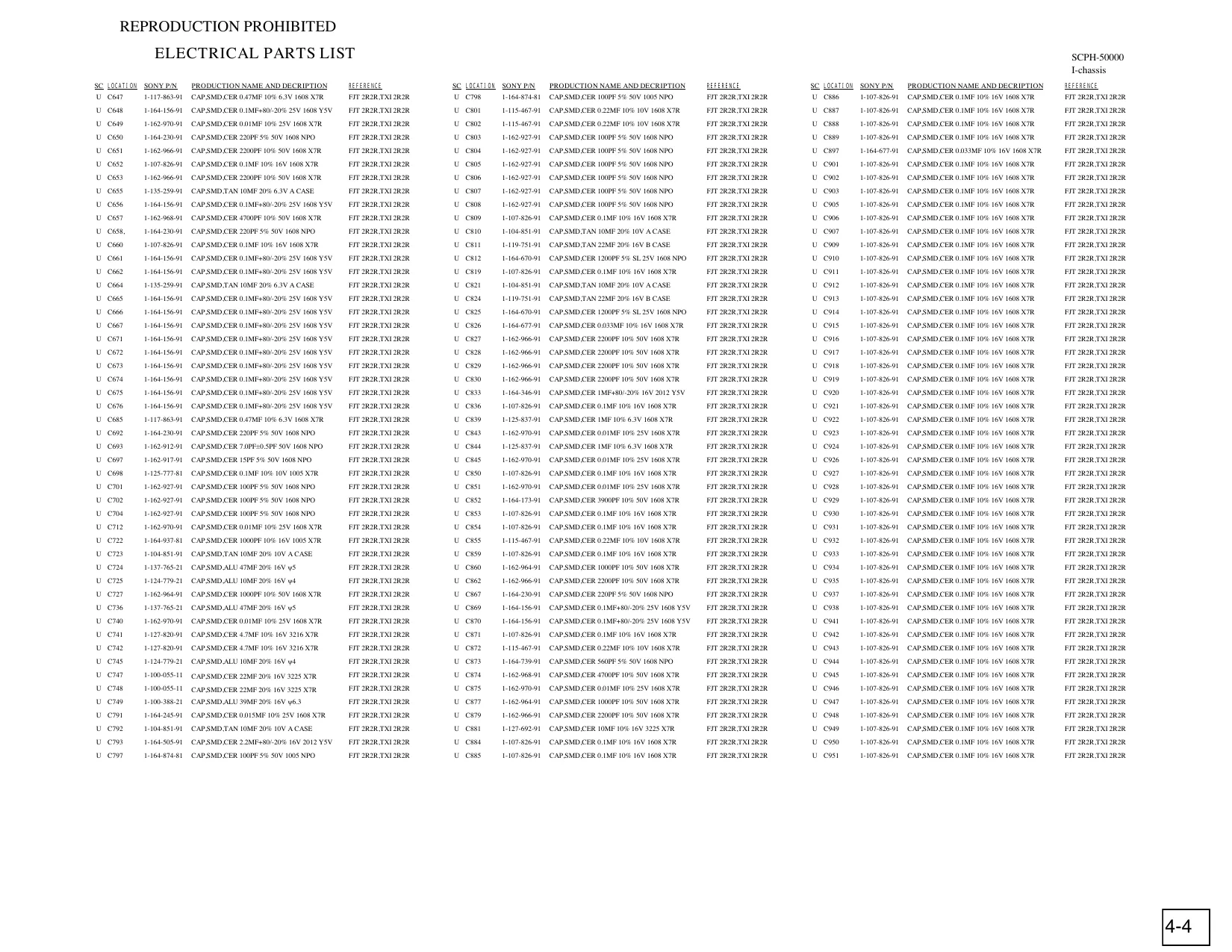
This page is a drawing, shown as the original scan.
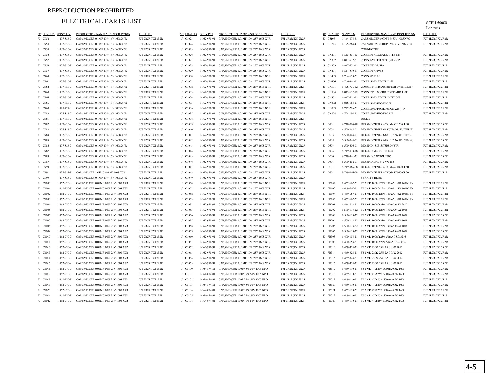
This page is a drawing, shown as the original scan.
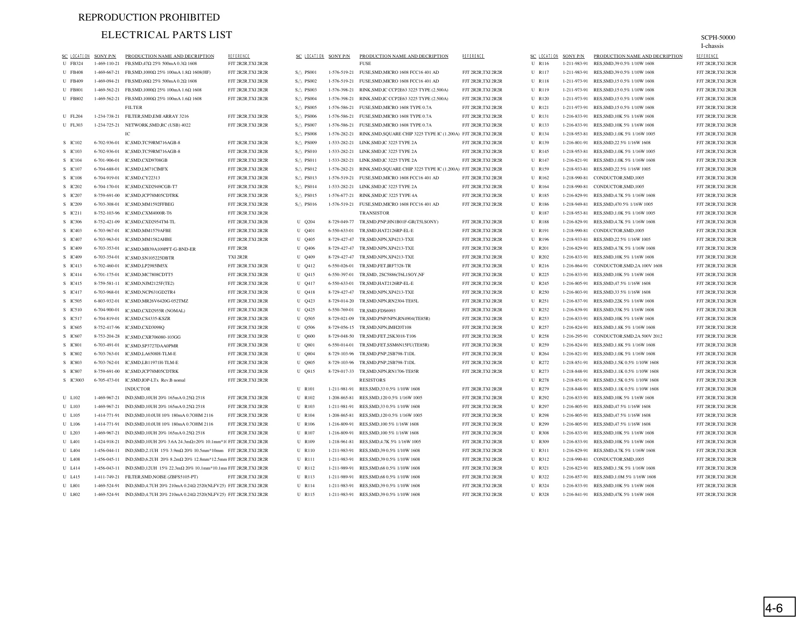
This page is a drawing, shown as the original scan.
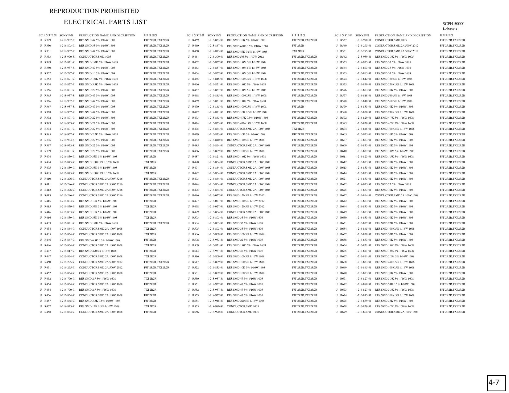
This page is a drawing, shown as the original scan.
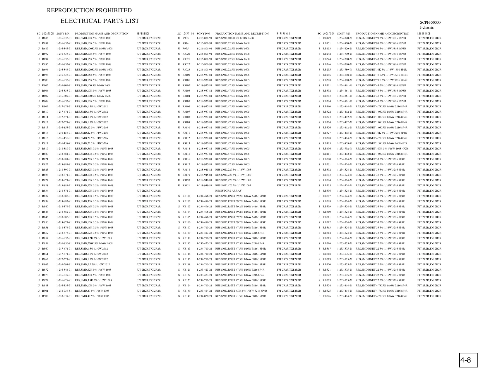
This page is a drawing, shown as the original scan.
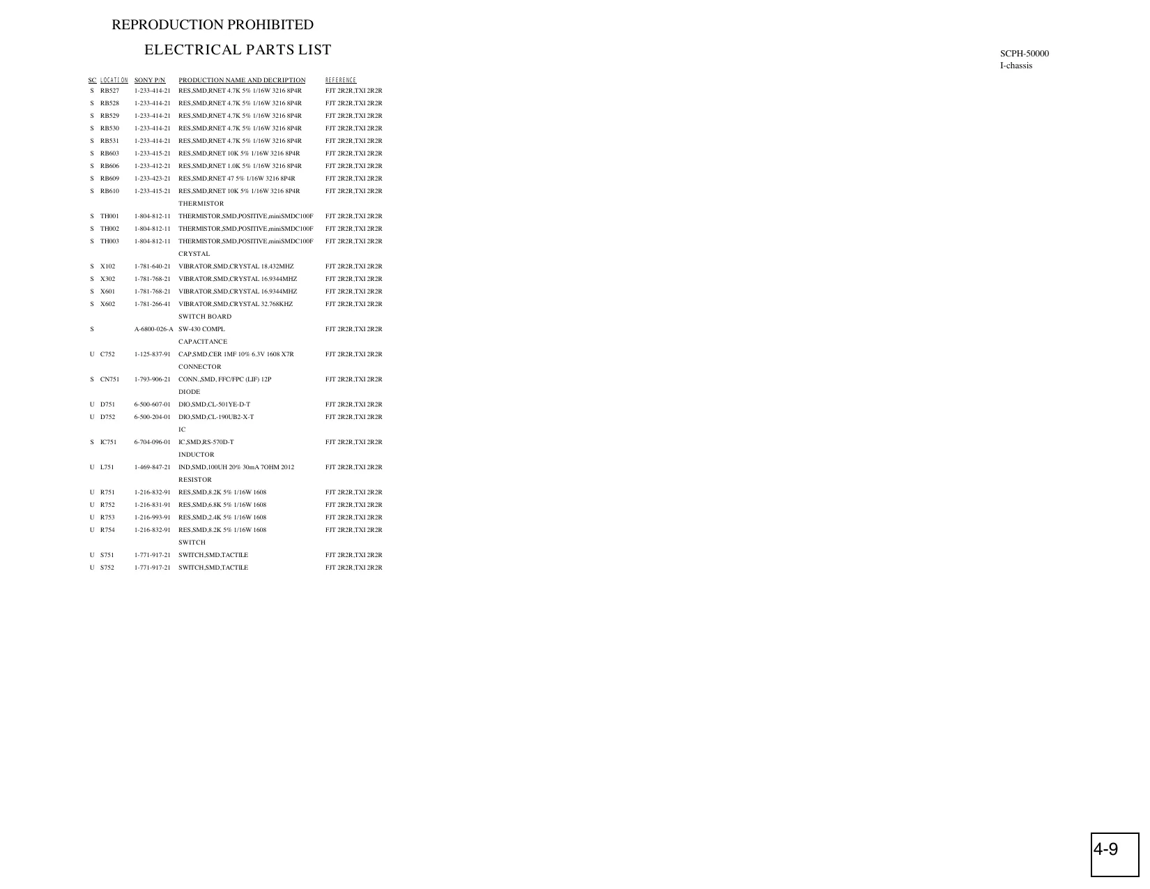
This page is a drawing, shown as the original scan.