Asteroids Cocktail TM-150 3rd Printing
Asteroids (rev 4) (Atari, 1979) · Technical Manual · 48 pages · 33 sections · original scan
This page is a drawing, shown as the original scan.
Sn i a eee oe a
Sine 208
mention this number whenever calling your
located on the outside rear of the
the chassis of the TV monitor,
iter santa a hr distributor for service.
Operation, Maintenance and Service Manual
Complete with Illustrated Parts Lists
Published by: ATARI INC. 1265 Borregas Avenue P.O. Box 427 Sunnyvale, California 94086
Copyright © 1979, 1980 by Atari, Inc. Alli rights reserved
No part of this publication may be reproduced by any mechanical. photographic, or electronic process, or in the form of a phonographic recording, ner may it be sored in a retrieval sysiem, transmitted, or otnerwise Copied for public or private use, without permission ‘rom the publisher ATARI Awarrer Communicators Comer QD Lithographed in the U.S.A MW
Table of Contents
1 Location Setup
Opening the Game Cabinet Game Inspection ....... Game Installation .
- Voltage Selection......... pom>
- Interlock and Power On/Off Switches
- Game Fuses...............00. Adjusting the Table Legs . Self-Test Procedure ... Game Piay....
- AttractMode ...
- Ready-to-Play Mode
- PlayMode.......... amm
- High Score Initial Mode ...............
2° Maintenance and Repair A. Cleaning B. Fuse Replacement .... C. Opening the Control Panel .
- Leaf Switch Replacement ..
- LED Switch Replacement D. TV Monitor Removal .......... £. Printed Circuit Board Replacement
- Game PCB Removal.......
- Regulator/Audio PCB Removal F. Game Operation .........-00.. 00.0 eee
3 Illustrated Parts Lists New Pants 0c cugeer cree eed ceases one OMMDDHAANGTNNYNN=
Figure 1 Figure 2 Figure 3 Figure 4 Figure 5 Figure 6
Figure 7 Figure 8 Figure 9 Figure 10 Figure 11 Figure 12 Figure 13 Figure 14 Figure 15 Figure 164 Figure 16B Figure 17 Figure +8 Figure 19 Coin Acceptor List of Illustrations
Overview of Game ... 0.6. cc eeee eee 2 Installation Requirements . 3 Power Supply 4 Interlock and Power On/Off Switches . 4 Adjusting the Table Legs 5 Location of Self-Test Switch, Volume Control and Option Switches .. . 6 Self-Test Procedure . 7 Option Switch Settings . : 8 Opening the Control Panel and Replacing witches . 13 TV Monitor Removal -14 Printed Circuit Board Removal 15 Power Distribution ........ .17 Signal Distribution - - 18 Final Assembly ..... 20 Control Panel Assembly ...........-..06 - 22 Asteroids Game PCB Assembly (-05 and -06 versions) 24 Asteroids Game PCB Assembly (-03 and -04 versions) . 8B Regulator/Audio PCB Assembly ............- -32 ty Assembly for X-¥ Games
If reading through this manual does not lead to solving a certain maintenance probiem, call Tele-Help™ at the Atari Customer Service office in your geographical area, as shown in one of the two maps below. Order all parts from the California office.
WEST and CENTRAL U.S.A.
Parts for all Atari Customers. Sales and Service
Atari Coin-Op Customer Service 1344 Bordeaux Drive, Sunnyvale, CA 94086 Telex 17-1103 (Monday - Friday, 7:30 - 4:00 pm Pacific Time) ie
= From California, Alaska or Hawaii ™ (408) 745-2900
em From anywhere else in this area toll-free (800) 538-1611
EAST U.S.A.
Sales and Service Only
Atari Inc. New Jersey Customer Service Office Cottontail Lane, Somerset, NJ 08873 Telex 37-9347
(Monday - Friday, 8:30 - 5:00 pm Eastern time)
From New Jersey (201) 469-5993 =
From anywhere else in this area toll-free (800) 526-3849
Lo
A. New Parts
The Cocktail Asteroids game has four new parts. |f you have worked on Atari games in the past, then you should be aware of these important differences. The new parts are:
- Power Supply Assembly. It covers a wider voltage range than before, has higher reliability, a smaller overall size, and all fuse numbers and fuse amperages are marked directly on the metal chassis.
- Game PCB Circuitry and TV Monitor. Most video games to date have used the raster scan method of display. This game uses vector generation with X and Y axes to allow greater contrast, a greater number of moving objects on the screen, and lines at any angle to be “drawn” on the screen,
- Cocktail Table Cabinet. This new cabinet design allows for adjustable height and easy access for servicing. The tempered glass top eliminates the possibility of spilied liquids entering into the cabinet.
- Coin Acceptor. This is the first use of this fixed
Cocktail Astercids™
TABLE TOP.
SUPPORT ARM
START SWITCHES TV MONITOR
CONTROL PANEL
G _A2 | REGULATOR/AUDIO PCB Zi ——— LAO > i POWER SUPPLY COIN ACCEPTOR
SPEAKER
LATCH
COIN COIN SWITCH, COUNTER ACCESS PANEL SELF-TEST SWITCH
AND VOLUME CONTROL
Figure 1 Overview of Game
B. Opening the Game Cabinet
Refer to Figure 1 and do the following:
Unlock and open the access panel.
- Reach inside and unfasten the hook-type latch on each end of the cabinet.
- Lift the table top until the support arm locks into place.
The inside of the cabinet, excluding the two control panels, is fully accessible for servicing.
To close the cabinet, do the following:
- Stand on the access-panel side of the cabinet and grasp the table top with the left hand.
- With the right hand, press the button at the middle of the support arm and pull the support arm toward you.
- Gently lower the table top to the closed position.
- Reach inside the access panel and lock the two latches.
- Close and lock the access panel.
C. Game Inspection
This game is ready to play upon removai from the shipping carton. However, your careful inspection is needed to supply the final touch of quality control. Please follow these steps to help us insure that your new game was delivered to you in good condition.
[compnatmecenenyes | Do not plug the game in yet!
- Examine the exterior of the game cabinet for dents, chips, or broken parts.
- Unlock and open the access panel of the cabinet and inspect the interior of the game as follows: a. Check that all plug-in connectors (on the game harness) are firmly seated. Replug any connectors found unplugged. DON’T FORCE CONNECTORS TOGETHER. The connectors are keyed so they only go on in the proper orientation. A reverse edge connector will damage a PCB. b. Check that ali plug-in integrated circuits on the game PCB are firmly seated in their sockets.
Awaarninc & To avoid possible unpleasant electrical shock, do not touch internal parts of the TV monitor with your hands or metal objects held in your hands!
c. Note the location of the game’s serial number—it is on the metallic label on the speaker side of the cabinet. Verify that the serial numbers also stamped on the Game PCB, Regulator/Audio PCB and TV Monitor are all identical. A drawing of the serial number locations is on the inside front cover of this manual. Please mention this number whenever you call your distributor for service. d. Check all major subassemblies such as the Power Supply, Control Panel and TV Monitor for secure mounting.
D. Game Installation
Figure 2 Installation Requirements
Power 175 waits Temperature 0 to 38°C (32 to 100°F) Humidity Not over 95% relative Space Required 60 x 81 cm (23% x 31% in.) Game Height 61 to 71 cm (24 to 281%. in)
- Voltage Selection
Before plugging in your game, make sure that the voltage selection plug on the power supply (see Figure 3) is correct for your location’s line voltage. Check the wire color on the plug and see if it is correct per the following list.
Line Voltage Range Voltage Selection Plug Color
90-110 VAC (100) Violet 105-135 VAC(120) Yellow 200-240 VAC(220) Blue 220-260 VAC(240) Brown
INTERLOCK SWITCH
BOTTOM VIEW
POWER ON/OFF SWITCH
Figure 4 Interlock and Power On/Off Switches
- Interlock and Power On/Off Switches
To minimize the hazard of electrical shock while working on the inside of the game cabinet, an interlock switch has been installed (see Figure 4). This switch removes all AC tine power from the game circuitry when the access panel is opened.
Check for proper operation of the interlock switch by doing the following:
Unlock and oper the access panel. Plug the AC line power cord into an AC outlet. Close the access panel. Set the power on/off switch to the on position. Within 30 seconds the TV monitor should display a picture.
- Slowly open the access panel. The TV monitor piciure should disappear when the panel is opened approximately 2.5cm (1 inch). Fons
- Game Fuses
For continued protection of your game, as well as. for the safety of the players, fuses must be replaced
USE ALL THREE BOLTS WHEN ATTACHING TABLE LEGS. only with fuses with identical ratings. These ratings are shown in Figure 17. See the schematic Drawing Package for the fuse functions.
information on the TV monitor fuses is contained in the TV monitor manual that is supplied with this game.
E. Adjusting the Table Legs
This cocktail table game is designed for three adjustable heights from 61 to 71 cm (24 to 28 1/2 in.). The table may be set at 61 cm (24 in.), 66 cm (26 1/8 in.) or 71 cm (28 1/2 in). To adjust the table height refer to Figure 5.
Figure 5 Adjusting the Table Legs
COIN SWITCH
VOLUME CONTROL WA
VOLUME DECREASE: TURN CLOCKWISE os OPTION SWITCHES
OFF
SS NOTUSED
SELF-TEST SWITCH
Figure 6 Location of Self-Test Switch, Volume Control and Option Switches
F. Self-Test Procedure
This game will test itself and provide data to demonstrate that the game’s circuitry and controls are operating properly. The data is provided on the TV monitor and the game speaker; no additional equipment is necessary. Part of the self-test procedure includes a display of the operator-selectable game options. Therefore, we suggest you run the self-test procedure anytime you need to change the game’s options.
To run the self-test, follow the instructions outlined in Figure 7.
Cocktail Asieroids™
Figure 7 Self-Test Procedure
(INSTRUCTION
- Set self-test switch to on position (see Figure 6). RESULTS IF TEST PASSES RESULTS IF TEST FAILS TV monitor displays RAM FAILURE is indicated by asequence of from 1 to 6 tones. A low-frequency picture as shown in Figure 8. tone is heard for each good RAM chip. A much lower frequency is heard for a failing RAM chip. The sequence stops with the last failing RAM chip. To restart the sequence, press the Reset pushbutton on the game PCB or set the self-test switch to off, then again to the on position. Identify the bad RAM chip with table below. Example: Three tones, then a tone of much lower frequency indicates failure of RAM chip Ré4.
TONE # RAM CHIP LOCATION
D2 E2 M4 R4 N4 P4 ROMI/PROM FAILURE is indicated by two columns or lines of numbers in the upper left-hand corner of the display. The number in the left column or first line indicates the failing ROM/PROM chip(s). Identify the bad ROM/PROM with table below. The number in the right column or second line indicates the failing data bit of the failing ROM/PROM. Identify the bad bit with the second table below. If more than one bit is failing, the disp\ayed number(s) are hexadecimal combinations of the numbers shown below. Examples:
- If bits D2 and D3 fail, C is displayed.
- If bits D2, D3 and D7 fail, 8C is displayed.
- If bits D4 and D5 fail, 30 is displayed.
- \f bits D1, D3, D5 and D6 fail, 6A is displayed Onsans
DISPLAYED NO. FAILING ROM/PROM
-05 & 06 PCB 03 & -04 PCB
| ° | NIP3 | Nips | K4,L4 |
2 F2,H1
| 5 | v2 | Fl | F2,L1 | 121 |
4 H2,J1
| 5 | H2 | D/E1 | H2,J1 | M2.M1 |
| : | EIF2 | 1 | K1J2 | Ra |
DISPLAYED NO. FAILING BIT "
1 00 2 o1 4 D2 8 D3 10 Da 20 DS 40 D6 30 o7
RAMSEL SIGNAL FAILURE is indicated by a BANK ERROR or PAGE SELECT ERROR message at lower middie of display.
- Activate all contro! panel and coin door switches. When satisfied with test, set self-test Switch to off position. 1 PLAYER START and 2 PLAYER START LEDs are lighted. Highpitched click for each activated switch. 1 PLAYER START and/or 2 PLAYER START LEDs not lighted.
High-pitched click sound is not heard for any particular switch.
Figure 8 Option Switch Settings
To change toggle positions of the switch assembly, you need not remove the game PCB. The switch, usually colored blue, is easily accessible when the game PCB is mounted in place. When changing the options, verify proper results on the TV monitor display during self-test. A switch toggie in the ‘on position is indicated by a 0 for that switch on the TV monitor dispiay. A switch in the off position is indicated by the number 1.
Toggle Settings of 8-Toggle Switch switcH SwiTcH IGNORE THiS TOGGLE 8 ToGate + IGNORE THIS ‘on Game PCB Option
| a | 7 | 6 | 5 | 4 | 2 | 2 | 1 |
| Qn | On | English | |||||
| On | Off | German | |||||
| Off | On | French | |||||
| or | on | Spanish |
On 4Ship Game ort 3.Ship Game
| On | On | Free Play |
| On | Off | 1 Goin tor 2 Plays |
| Off | On | 1 Goin tor 1 Play |
| off | of | 2Coins for 1 Play |
Photograph above shows toggles 1. 2, ‘47 on, and toggles 3 and & ofl
G. Game Play
Atari’s Asteroids game has five possible modes of operation: Attract, Ready-to-Play, Play, High Score Initial, and Self-Test. Self-Test is a special mode for checking the game switches and computer functions. You may enter this mode at any time. When entered, all game credits are cancelled.
- Attract Mode
The attract mode begins when power is applied to the game, after a play or high score initial mode, or after self-test. This mode is continuous and is only interrupted when a coin is inserted and accepted or when in self-test. In this mode, the TV monitor displays two possible pictures. Both pictures have three score values across the top of the screen and a message that states the number of coins for a game. The middle score represents the high score to date. The left score is for player 1. The right score is for player 2.
One picture displays asteroids and an occasional enemy spaceship “‘floating” across the screen. The second picture displays up to 10 of the highest scores since the game was last powered up or since the last self-test. These two displays alternate every 16 seconds.
- Ready-to-Play Mode
This mode begins when sufficient coins have been accepted for a one or two-player game. It ends when the 1 PLAYER START or 2 PLAYER START pushbutton is pressed. When this mode begins, the message PUSH START flashes immediately below ihe center score at the top of the screen. The displayed pictures are otherwise the same as those shown in the attract mode.
- Play Mode
The play mode begins when either start pushbutton is pressed. The mode ends when the player's last ship of the game is lost.
If the 1 PLAYER START pushbutton was pressed, the following picture is displayed: the PLAYER 2's score disappears; the PLAYER 1's score becomes 00, and the number of ships (3 or 4, depending on the operator's setting) for the game appears below that score. The message PLAYER 1 also appears below the high score to date. Two seconds after pressing the 1 PLAYER START button the PLAYER 1 message disappears, and the game ship appears at the center of the display. Four large asteroids appear and drift in from the outer edges of the display.
\f the 2 PLAYER START pushbutton is pressed, ihe following picture is displayed: the PLAYER 1 and PLAYER 2 scores become 00, and the number of ships for the game appears below each score. The player 1 score also flashes as the message PLAYER 1 appears below each score. The player 1 score also flashes as the message PLAYER 1 appears below the high score to date. Two seconds after the 2 PLAYER START pushbutton is pressed, the PLAYER 1 message disappears. The game ship for player 1 appears at the center of the display as four large asteroids appear and drift in from the outer edges of the display.
By pressing the LEFT ROTATE and RIGHT ROTATE pushbuttons on the control panel, the player may aim the spaceship toward any of the asteroids. By pressing the FIRE pushbutton, the player may shoot at the asteroids.
When shot, each large asteroid divides into two medium-sized asteroids and the game adds twenty points to the player’s score. Medium-sized asteroids, when shot, divide into two small-sized asteroids, and the player receives fifty points. Smallsized asteroids, when shot, will completely disappear, and the game awards 100 points to the player. When a player has shot all asteroids, a new set of large asteroids again appear and drift in from the outer edges of the TV monitor dispiay. At the beginning of the game, four large asteroids appear. At the beginning of the next cycle when large asteroids reappear, there are six, the next time eight, and thereafter ten—to increase player challenge.
At any time during game play, a flying saucer may appear from either side of the display. The game awards 200 points for shooting a large saucer and 1000 points for a small saucer. (The latter is a smaller target for players, though not any faster moving than the large one. It also shoots more accurately.)
The player's objective in the game is to shoot and destroy as many asteroids as possible before all his or her spaceships are destroyed. A ship is destroyed if an asteroid or saucer smashes into it, or if a flying saucer shoots it. To prevent losing a ship, the player may press the THRUST pushbutton to move out of the path of an asteroid or saucer. As an emergency maneuver, players can press the HYPERSPACE pushbutton: the ship disappears and reappears at a random location on the display—however, possibly right on top of, or in the path of, an asteroid. The ship may also explode on reentry.
The game awards an exira ship each time a player's score reaches muitiples of 10,000; i.e., one ship is awarded at 10,000 points, another ship at 20,000 points, etc.
When the last ship of the game is destroyed, the message GAME OVER appears below the high score. This message remains for 3 seconds before the high score initial mode begins.
- High Score Initial Mode
At the beginning of the high score initial mode, the player instructions appear at the top of the screen, and A __ __ appears at the lower center of the display. Players enter initials one character ata time. By pressing the LEFT ROTATE pushbutton, the display character steps through the alphabet from A to Z. By pressing the RIGHT ROTATE pushbutton, the character steps through the alphabet from A to a blank, then from Z to A.
Once the game displays the desired letter, players should press the HYPERSPACE pushbutton to record the letter; then an A appears in the next space.
If players need only two letters for their initials, they should use the blank between Z and A in one of the three locations. Pressing the HYPERSPACE pushbutton a third time will cause the initials and game score to be transferred to the “10 highest scores” listing that appears during the attract mode.
This page carries no recoverable text. It is a drawing or a photograph. See the original scan.
This Atari game requires certain maintenance to keep it in good working order. Clean, properly maintained games attract players and earn more profits.
The most important maintenance item is running the self-test every time you collect money from the cash box. Just looking at a game will not tell you if LED switches or leaf switches are broken or if LEDs have burned out. The self-test will inform you of any of these problems.
Second, you should regularly clean the outside of the game and the coin acceptor. In addition, you will need to regularly clean the leaf switch contacts: for details see this chapter. .
Maintenance and Repair
A. Cleaning
The exterior of the game cabinet and the metal and glass surfaces may be cleaned with any nonabrasive household cleaner. If desired, specia! coin machine cleaners that leave no residue can be obtained from your distributor.
B. Fuse Replacement
This game contains six fuses — all on the power supply assembly (not including the TV monitor fuses.) Replace fuses only with the same type as listed in Figure 18 of this manual. See the Quadrascan TV monitor manual, TM-151, for the monitor fuse data.
C. Opening the Control Panel
To open the control panel, simply unscrew the two Allen-head screws at the top of each control panel. Once the screws are removed, tilt the control panel towards you.
- Leaf Switch Replacement
All five of these leaf switches operate on 5 volts at very low current. Therefore, pitting of these switches will be extremely rare. Probably the only reason that pitting would occur is in very highhumidity locations. Don't burnish the switch contacts. Burnishing them removes their plating, thus increasing the corrosion of the contacts. The best method of cleaning ihe switch contacts is to wipe them with a nonabrasive surface. A business card works great.
To replace any switch, remove both of its screws. with a Philips-head screwdriver—see Figure 9.
If the white button itself needs to be replaced, turn the stamped nut with a wrench in a counterclockwise direction, as seen from the inside of the control panel. The white ring on the outside of the contro! panel should not spin, due to its design.
- LED Switch Replacement
The light-emitting diode (LED) switches on the side of the cabinet above the coin machine have a very low failure rate. In case a switch should ever be suspect, first test it per the description that follows. To replace a switch, refer to Figure 9.
Remove the wires from the suspected switch.
- Set ohmmeter to R x 1 scale, then zero the meter.
- Connect ohmmeter leads to appropriate LED switch contacts (see Figure 9 for designation of switch contacts).
- Check contacts (push and release the switch button) for closed and open continuity.
- If the contacts do not operate sharply or always remain closed or open, then replace the LED switch as outlined in the figure.
Cocktai} Asteroids™
COMMON LIGHT-EMITTING CONTACT | QIODE(L.E.0.) CONTACTS
~NORMALLY OPEN (N.O.) CONTACT
NORMALLY CLOSED (N.C.) CONTACT
L.E.D SWITCH: TO REMOVE TURN COUNTERCLOCKWISE
To remove LED switch:
© Remove all wires from the faulty switch. @ Turn the switch counterclockwise while holding the black cone-shaped nut on the outside of the control panel. @ Install a new switch using the reverse procedure. Reconnect the harness wires.
TURN NUT TO REMOVE WHITE BUTTON
Adjust leaf switches for a narrow gap. When a switch button is depressed, the resulting wiping action of the contacts provides a selfcleaning feature.
Figure 8 Opening the Control Panel and Replacing Switches
D. TV Monitor Replacement
Awarninc A
High voltages may exist in any TV monitor, even with power disconnected. Use extreme caution and do not touch electrical parts of the TV yoke area with your hands or with metal objects in your hands! If you drop the TV monitor and it breaks, it will implode! Shattered glass and the yoke can fly 6 feet or more from the implosion. Use care when replacing any TV monitor. If you should need to remove the Quadrascan X-Y TV monitor, follow steps 1 thru 4 as follows. Refer also to Figure 10 below.
Unlock and open the access panel.
- Unfasten and open the table top.
- Locate the 12-pin Molex connector between the game PCB and the TV monitor. Separate this connector.
- Locate the four Phillips-head screws (one at each corner of the TV monitor screen) that attach the TV monitor to the top of the cabinet. Remove these screws.
- Carefully lift the TV monitor up and out of the cabinet.
Figure 10 TV Monitor Removal
E. Printed Circuit
Unlock and open the access panel. »
om Remove the 44-pin edge connector from the Board Replacement = © irsnisie or ine game Poe.
You may wish to remove the game printed circuit c. Locate the two Philips-head screws that exboard (PCB) or the Regulator/Audio PCB for service tend through the PCB and into the two or inspection. To do this, refer to Figure 11 and proceed as follows:
- Game PCB Removal wood blocks at the lock side of the access panel. Remove these two screws.
d. Remove the PCB from the access panel by lifting up and pulling it out of the plastic PCB mounting (extrusion) at the hinge-side of the access panel.
Figure 11 REGULATOR/AUDIO PCB
Printed Circuit Board Removal
e. Reinstall the PCB, making sure that the 44-pin edge connector is properly plugged in. Note that the connector is keyed to fit in only one way, so if it doesn’t slip on easily, don't force it! A reversed connector will probably damage your game and will void the warranty. f. Check that the operation of the game is cortect by performing the self-test. This is especially important with any game when you replace a PCB. Unless you are a qualified technician, do not adjust the knob on the PCB.
- Regulator/Audio PCB Removal
a. Unlock and open the access panel. Remove the three plug-in connectors. Locate the two Philips-head screws that extend through the PCB and into the two wood blocks at the top two corners of the PCB. Remove these two screws. d. Remove the PCB from the wall of the cabinet by pulling it up and out of the wood slot. e. Reinstall the game PCB. f. Check that the operation of the game is correct by performing the self-test. This is especially important with any game when you replace a PCB. Unless you are a qualified technician, do not adjust the knob on the PCB.
F. Game Operation
With this manual you received two large sheets that contain the wiring and schematic diagrams for the Asteroids game. Sheet 1, Side A, includes information that shows the arrangement of these diagrams. These diagrams include information that explains the functions of the circuits and defines inputs and outputs.
Atari’s Asteroids is a microprocessor-controlled game. The microprocessor is contained on the game PCB. The game PCB receives switch inputs from the control panel, coin mechanism and start switches. These inputs are processed by the game PCB and output to the TV monitor, Regulator/Audio PCB and LED switches.
The TV monitor is an X-Y monitor. Therefore, the monitor receives signals for the X,Y and Z axes. Since the location of the beam in the monitor is totally controlled by the X- and Y-axis outputs of the game PCB, the game PCB does not contain a standard sync circuit. The X- and Y-axis inputs to the monitor step in increments of 1024 steps for the X (horizontal) axis and 768 steps for the Y (vertical) axis. The Z axis merely controls the intensity of the beam.
The Regulator/Audio PCB performs two functions: 1) regulates the +10.3 VDC from the power supply to + 5 VDC, and 2) amplifies the audio output from the game PCB. The +5 VDC from the Regulator/ Audio PCB provides most logic power to the game PCB. The audio output from the Regulator‘Audio PCB directly drives the game speakers and is controlled by the volume control locaied inside the access panel and on the floor of the cabinet.
The Power Supply is the source of all voltages in the game. These voltages are protected by five fuses in the fuse block on the Power Supply chassis. The primary winding of the Power Supply transformer is protected by the cartridge type fuse in the power supply chassis.
Figure 12 illustrates the distribution of power in this game. Figure 13 illustrates the distribution of signals.
TV MONITOR INTERLOCK SWITCH
REGULATOR/AUDIOPCB
ON/OFF SWITCH
AC POWER CORD
COIN ACCEPTOR
GAME PCB
POWER SUPPLY
Figure 12 Power Distribution
SPEAKER TV MONITOR
SELF-TEST SWITCH CONTROL PANEL
START SWITCHES REGULATOR/AUDIO I! PCB
i
= SIGNALS TYPICAL FOR BOTH CONTROL PANELS
SLAM SWITCH GAME PCB COIN ACCEPTOR
VOLUME CONTROL
COIN COUNTER
Figure 13 Signal Distribution
Cocktail! Asteroids™
illustrated Parts Lists
The purpose of this chapter is to provide you with the necessary information for ordering replacement parts for your Atari Asteroids game. Please note that, for simplicity, common hardware has been deleted from most of these parts lists. This includes screws, nuts, washers, bolts, etc.
When ordering parts from your distributor, give the part number, part name, applicable figure number of this manual, and serial number of your game. This will help to avoid confusion and mistakes in your order. We hope the results will be less downtime and more profit from your game.
s
Cocktan ASterords'™
NOTICE TO ALL PERSONS RECEIVING THIS DRAWING CONFIDENTIAL: Reproduction forbidden without the specific writien permission of Atari, Inc., Sunnyvale, CA. This drawing 15 only conditionally. issued, and neither receipt nor possession thereat confers or transless any right in, of license to use, the subject matter of the drawing or any design oF technical information shown thereon, nor any faght 10 reproduce this drawing or any part thereot. 0: 7 ‘ 135852-01, 035879-01 ten license, no right to reproduce this drawing is granted or the subject matte: thereof unless by wrilten agreement with or written permission from the corporation,
035911-01 035850-01
A035906-01 OR 02
TM-151 92-045 035867-02 \34487-14 _, CONTROL PANEL ASSEMBLY SEE FIGURE 15
68-002 007882.02
REGULATOR/AUDIO pene1awo PCB ASSEMBLY 82009 SEE FIGURE 17 034536-02 COIN ACCEPTOR ‘A034831.01 MOUNT ASSEMBLY nOsees7 01 SEE FIGURE 19 A035992-01 OR-020R-03 A035840-01 035917-01 A007838-01
48.004 78-3408 . o SD POWER SUPPLY 82-8940 NN a ASSEMBLY
‘SEE FIGURE 18 4036320-01 i) 19-9032 69001 035847-01 even nodaageO1 GAME PCB ASSEMBLY 03574502 SEE FIGURE 16
Figure 14 Final Assembly A035836-xx EE
Figure 14 Parts List
Part No, Description
A002465-01 Coin Counter Assembly A007638-01 Slam Switch Assembly A036320-01 Audio Control/Test Switch and Coin Switch Assembly A034631-01 15 Amp @ 125V (10 Amp @ 250V) DPDT Toggle Switch A035897-01 AC Harness Assembly A035840-01 Main Harness Assembly A035906-01 Top Support Assembly (Right Side) A035906-02 Top Support Assembly (Left Side)
| A035992-01 | Strain Relief Power Cord Assembly | (U.S.A.) |
| A035992-02 | Strain Relief Power Cord Assembly | (European) |
| A035992-03 | Strain Relief Power Cord Assembly | (Australian) |
DP-150-01 Sheet 1 of Schematic Drawing Package DP-150-02 Sheet 2 of Schematic Drawing Package ST-150 Self-Test Label TM-151 Quadrascan™ “X-Y" Monitor Manual 19-9032 50-Ohm, 12.5 Watt, Wire-Wound Rheostat 48-004 16-Ohm, 4-Watt, 4-inch General Loudspeaker 62-039 SPDT Momentary-Contact Pushbutton Switch 68-002 30-Amp Interlock Switch 69-001 DPDT Slide Switch 71-2110 Panel Cartridge Lock Mechanism 75-9910W0 15/32-32 Steel Stamped Nut 78-3408 Spring Draw Latch 82-8940 #3/8-16 x 22" Button-Head Hex Socket Machine-Thread Screw 92-045, 15” X-Y Monitor 007882-02 Interlock Switch Cover 03312701 Black Molded Polycarbonate Switch Bushing 034487-14 #10-32 x 7/8" Button-Head Hex-Head Machine-Thread Screw with Thread Lock Compound 034536-02 Foam Vibration Damper 035745-02 18" PCB Retainer 035845-01 Coin Box Lid 035847-01 Coin Box 035850-01 Latch Bracket 035852-01 Corner Bracket 035867-02 Bronze-Color Acrylic Overlay 035879-01 Glass Top with Graphics 035911-01 Monitor Beze! 035917-01 On/Off Switch Cover
035878-01
NOTICE TO ALL PERSONS RECEWING THIS CONFIDENTIAL: Reproduction forbidden without the specific written permission of Atari, Inc., ‘Sunnyvale, CA. This drawing is only conditionally issued, and neither receipt nor possession thereot confers or transfers any fight in, or license to use, the subject matter ofthe crawing or any design ot tegnnical information shown thereon, nor any right to reproduce this drawing or any part thereo! Except for manufacture by vendors of Atari, Inc., and for manufacture under the corporation's writ: Jen license, no right to reproduce this drawing is granted of the subject matter thereo! unless by ‘written agreement with or written permission from the corporation. A035842.01
Figure 15 Control Panel Assembly A035910-01 D
Parts List
Part No. Description
A035842-01 Contro} Panel Harness Assembly A036046-01 Button Assembly 75:9910NO 5/8-11 Steel Stamped Nut 035878-01 Controt Panel with Graphics 160001-001 Leaf Switch with Button Holder 160004-001 Leaf Switch Only
This page carries no recoverable text. It is a drawing or a photograph. See the original scan.
This page is a drawing, shown as the original scan.
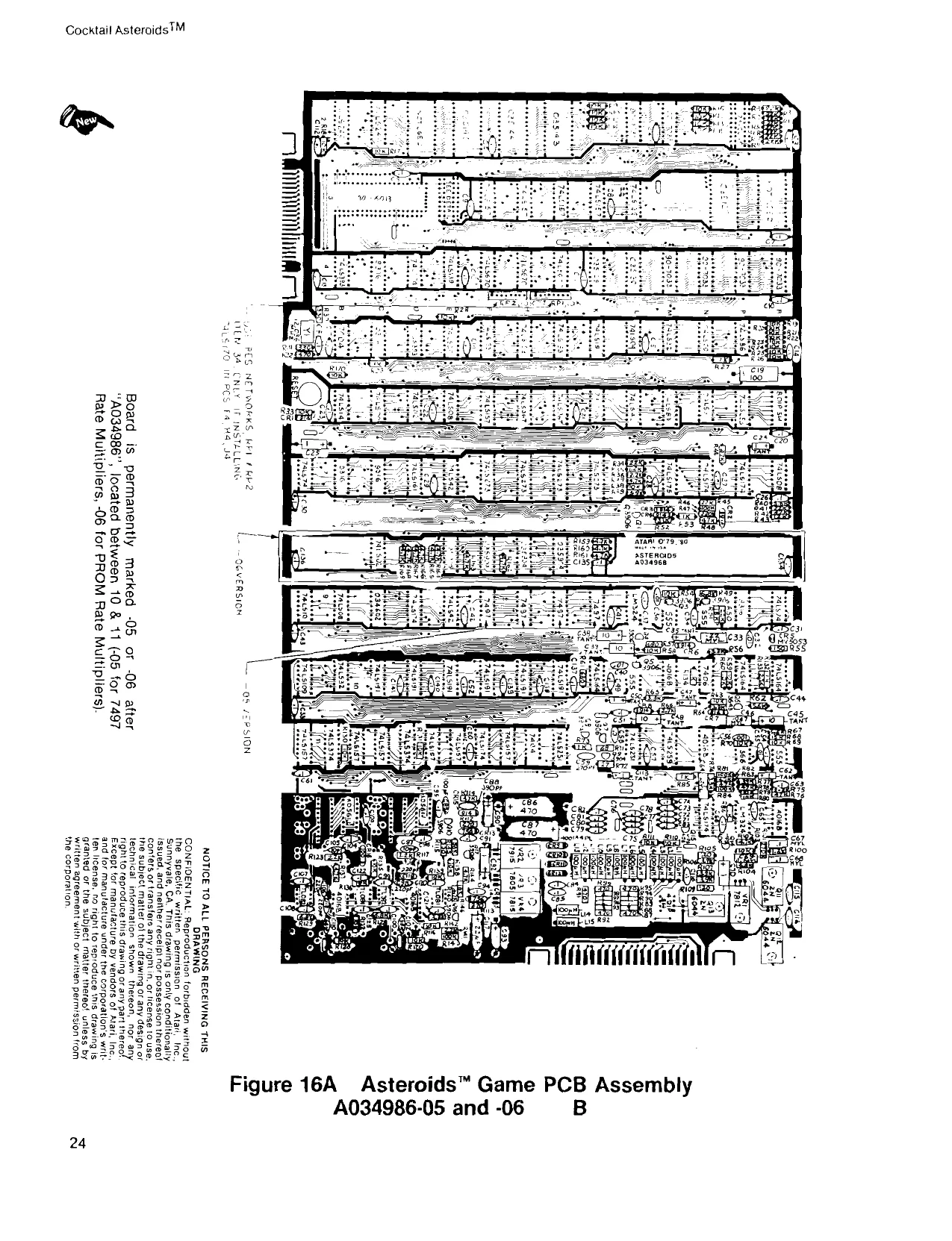
Figure 16A Asteroids™ Game PCB Assembly Parts List
| tem | Part No. | Description (Reference Designations and Locations in Bold) |
| 2 | 110000-270 | 27 Ohm, +5%, %W Resistor (R72) |
| 3 | 110000-680 | 68 Ohm, +5%, YW Resistor (R71) |
| 4 | 410000-121 | 120 Ohm, +5%, %W Resistor (R105, 109) |
| 5 | 110000-151 | 150 Ohm, +5%, ¥W Resistor (R55) |
| 6 | 410000-331 | 330 Ohm, +5%, YaW Resistor (R30, 31, 115) |
| 7 | 110000-471 | 470 Ohm, +5%, ¥4W Resistor (R32, 87-99) |
| 8 | 110000-681 | 680 Ohm, +5%, %4W Resistor (R57, 61) |
| 9 | 1410000-102 | 1K Ohm, +5%, %W Resistor (R27, 29, 53, 73, 85, 86, 132, 134) |
| 10 | 110000-271 | 270 Ohm, +5%, %W Resistor (R112, 113) |
| "1 | 110000-122 | 1.2K Onm, +5%, YW Resistor (R35, 100) |
| 12 | 110000-222 | 2.2K Ohm, +5%, YW Resistor (R36, 75, 117, 123, 133,141) |
| 13 | 110000-272 | 2.7K Ohm, +5%, YW Resistor (R66) |
| 14 | 110000-332 | 3.3K Ohm, +5%, YW Resistor (R56, 65, 74, 142) |
| 15 | 110000-392 | 3.9K Ohm, +5%, %W Resistor (R39, 64, 106-108) |
| 16 | 110000-472 | 4.7K Ohm, +5%, YW Resistor (R37, 82, 102, 137, 140, 144 [R159-169 used on -06 |
PCB only)
| 7 | 110000-562 | 5.6K Ohm, +5%, YaW Resistor (R40, 62, 67) |
| 18 | 110000682 | 68K Ohm, +5%, YW Resistor (R49, 104, 128, 129) |
| 20 | ~ 110000-103 | 10K Ohm, +5%, %W Resistor (R9-26, 28, 33, 38, 54, 58-60, 63, 69, 70, 79, |
80, 103, 110, 111, 116, 122, 130, 131, 135, 136, 138, 139, 170)
| 21 | 110000-123 | 12K Ohm, +5%, YW Resistor (R43) |
| 22 | 110000-153 | 15K Ohm, +5%, %W Resistor (R68) |
| 23 | 119000-183 | 18K Ohm, +5%, %W Resistor (R51, 146) |
| 24 | 110000-223 | 22K Ohm, +5%, %W Resistor (R1-8, 34, 41, 45, 50) |
| 25 | 410000-333 | 33K Ohm, +5%, %W Resistor (R52) |
| 26 | 110000-473 | 47K Ohm, +5%, “%W Resistor (R42, 44, 48, 76, 78, 83, 114) |
| 27 | 110000-563 | 56K Ohm, +5%, YW Resistor (R145) |
| 28 | 110000-104 | 100K Ohm, +5%, YW Resistor (R46, 81, 84, 143) |
| 29 | 110000-224 | 220K Ohm, +5%, ‘W Resistor (R47) |
| 30 | 110000-274 | 270K Ohm, +5%, %W Resistor (R101) |
| 33 | 110000-393 | 39K Ohm, +5%, YW Resistor (R77) |
| 34 | 19-007 | 40K Ohm, 8-Pin Resistor Network. Used only with 74LS170 at position F4, H4, J4. |
| 35 | 19-315103 | 10K Ohm Vertical-Mounting Cermet Trimpot, Bournes Series |
3352V-1-10K (R106, 126)
| 39 | 21-101104 | -luf, | 10%, Radial-Lead Epoxy-Dipped 100V Mylar Capacitor (C64, 67-69) |
| 41 | 21-101473 | .047 uf, + 10%, Radial-Lead Epoxy Dipped 100V Mylar Capacitor (C46) | |
| 44 | 24-250105 | 1.0 uf Aluminum Electrolytic Fixed Axial-Lead 25V Capacitor (C25, 70, 90, 92, |
93)
| 45 | 24-250107 | 100 uf Aluminum Electrolytic Fixed Axial-Lead 25V Capacitor (C19) |
| 46 | 24-250477 | 470 uf Aluminum Electrolytic Fixed Axial-Lead 25V Capacitor (C86, 87) |
| 47 | 24-250226 | 22 uf Aluminum Electrolytic Fixed Axial-Lead 25V Capacitor (C117) |
| 49 | 422002-102 | 001 uf Ceramic-Disc 25V Radial-Lead Capacitor (C56) |
| 50 | 100015-403 | 01 uf Ceramic-Disc 25V Radial-Lead Capacitor (C27, 32, 36, 40, 55, 58) |
| 51 | 29-088 | -1 uf Ceramic-Disc 25V Radial-Lead Capacitor (C3-18, 20-23, 26, 28-31, 34, 37, |
41-44, 49, 51-54, 57, 60, 61, 63, 65, 66, 71-85, 91, 94-96, 99, 100, 103, 104, 107, 108, 112, 114-116, 120-123, [134-136 used on 06 PCB only], 137-141)
| 53 | 28-101100 | 40 pf Radial-Lead Epoxy-Dipped 100V Mica Capacitor (C97, 105) |
| 54 | 28-101680 | 68 pf Radial-L.ead Epoxy-Dipped 100V Mica Capacitor (C102, 110) |
| 55 | 28-101101 | 100 pf Radial-Lead Epoxy-Dipped 100V Mica Capacitor (C89) |
| 56 | 28-101221 | 220 pf Radial-Lead Epoxy-Dipped 100V Mica Capacitor (C98, 106, 118, 119) |
| 57 | 28-101271 | 270 pf Radial-Lead Epoxy-Dipped 100V Mica Capacitor (C59) |
| 58 | 28-101391 | 390 pf Radial-Lead Epoxy-Dipped 100V Mica Capacitor (C88) |
| 61 | 29-006 | 1.0 uf, + 10%, 35V Tantalum Capacitor (C24, 35, 47, 50, 62, 113) |
| 63 | 29-046 | 10 uf, + 10%, 20V Tantalum Capacitor (C38, 39, 45, 48) |
65 31-1N100 100V Type-1N100 Switching Diode (CR16)
Cocktail Asteroids™M
Figure 16A Asteroids™ Game PCB Assembly, continued Parts List
Part No. Item Description (Reference Designations and Locations in Bold)
| 66 | 31-1N914 | 75V Type-1N914 Switching Diode (CR1-4, 6-8, 15) |
| 67 | 31-1N4001 | SOV Type-1N4001 Silicon Rectifier Diode (CR9-12) |
| 68 | 31-1N756A | 8.2V, +5%, 1N756A Zener Diode (CR13, 14) |
| 71 | 33-2N3906 | Type-2N3906 PNP Switching and Amplifying Transistor (Q1-5, 7, 10, 16, 17) |
| 72 | 34-2N3643, | Type-2N3643 NPN Silicon Transistor (Q6) |
| 73 | 34-2N3904 | Type-2N3904 NPN 60V 1-Watt Transistor (Q8, 9) |
| 74 | 34-2N6044 | Type-2N6044 Darlington NPN Transistor (Q11-13) |
| 75 | 34-MPSA06S, | Type-MPSAO6S NPN 80V 500ma Transistor (Q14, 15) |
| 78 | 37-74LS00 | Type 74LS00 Integrated Circuit (N5, C6) |
| 79 | 37-74LS02 | Type 74LS02 Integrated Circuit (D6, [C8 used only on -06 PCB) |
| 80 | 37-7404 | Type 7404 Integrated Circuit (B5, 11) |
| 81 | 37-74LS04 | Type 74LS04 Integrated Circuit (L5) |
| 82 | 37-7406 | Type 7406 Integrated Circuit (N10) |
| 83 | 37-74LS08 | Type 74LS08 Integrated Circuit (E6, K6, R7, B9) |
| 84 | 37-74LS10 | Type 74LS10 Integrated Circuit (A9) |
| 85. | 37-74LS14 | Type 74LS14 Integrated Circuit (B6) |
| 86 | 37-74LS20 | Type 74LS20 Integrated Circuit (E5) |
| 87 | 37-74LS32 | Type 74LS32 Integrated Circuit (M5, N6, B10) |
| 88 | 37-74LS42 | Type 74LS42 Integrated Circuit (L6, E7, E9) |
| 89 | 37-74LS74 | Type 74LS74 Integrated Circuit (D4, A7, R9) |
| a1 | 37-74LS83 | Type 74LS83 Integrated Circuit (M6) |
| 92 | 37-74LS86 | Type 74LS86 Integrated Circuit (P5) |
| 93 | 37-7497 | Type 7497 Integrated Circuit. Used only on -05 PCB = (F9, H9, J9, K9) |
| 94 | 37-74LS109 | Type 74LS109 Integrated Circuit (A10) |
| 95 | 37-74LS139 | Type 74LS139 Integrated Circuit (L3, E4) |
| a7 | 37-74LS157 | Type 74LS157 integrated Circuit (F3, H3, J3, K3, Fé, A11, B/C11, C11, D/E11, E11, |
FIH11)
| 98 | 37-74LS161 | Type 74LS161 Integrated Circuit (D7) | |
| 99 | 37-74LS164 | Type 74LS164 integrated Circuit (K10, P10, R10) | |
| 104 | 37-74LS174 | Type 74LS174 Integrated Circuit (N7, P7, D9, N12, F11) | |
| 102 | 37-74LS175 | Type 74LS175 Integrated Circuit (M7) | |
| 104 | 37-74LS191 | Type 74LS191 integrated Circuit | (K5, C10, D10, E10, F10, H10, J10) |
| 105 | 37-74LS193, | Type 74LS193 Integrated Circuit (F5, HS, J5) | |
| 106 | 37-74LS244 | Type 7415244 Integrated Circuit (B2, C2) | |
| 107 | 37-74LS245 | Type 74LS245 integrated Circuit | (P2, E3) |
OR .
| 108 | 37-8304B | Type 8304B Integrated Circuit—substitute for item 107 (P2, €3) |
| 110 | 37-74LS251 | Type 74LS251 Integrated Circuit (J11, L11) |
| 111 | 37-74LS253 | Type 74LS253 Integrated Circuit (P6) |
| 12 | 37-74LS259 | Type 74LS259 Integrated Circuit (M11) |
| 113 | 37-74LS273 | Type 74LS273 Integrated Circuit (F7, H7, J7, K7) |
| 114 | 37-74LS367 | Type 74LS367 Integrated Circuit (H6, J6) |
| 116 | 37-74LS393 | Type 74LS393 Integrated Circuit (84, D5) |
| 117 | 37-74L8374 | Type 74LS374 Integrated Circuit (B11, D141) |
OR
| 118 | 37-74LS272 | Type 74LS273 Integrated Circuit—substitute for item 117 (B11, D411) |
| 119 | 37-74LS670 | Type 74L9670 Integrated Circuit (F4, H4, J4) |
OR
| 120 | 37-74LS170 | Type 74LS170 Integrated Circuit—substitute for item 119 (F4, H4, Ja) |
| 121 | 37-9316 | Type 9316 Integrated Circuit (C4, C5, P9, 87, C7) |
| 122 | 37-LM324 | Type LM324 integrated Circuit (L9, P12) |
| 124 | 37-585 | Type 555 Timer Integrated Circuit (M9, N9, L10, R11) |
| 125 | 37-566 | Type 566 Function Generator Integrated Circuit (P11) |
| 127 | 37-4016B | Type 4016B Integrated Circuit (M10, N11, R12, B13, D13) |
| 128 | 37-TLOB2CP | Type TLO82CP Integrated Circuit (A13, C13) |
| 129 | 37-AD561J | Type ADS561J Integrated Circuit (B12, D12) |
| 130 | 137108-001 | Type TLO81CP Operational Amplifier Integrated Circuit (B/C13, E13) |
| 132 | 37-7805 | + 5V Voltage Regulator (VR3) |
Cocktail Asteroids™M
Figure 16A Asteroids™ Game PCB Assembly, continued Parts List
37-7812 37-7815 37-7915 38-MV5053 41-3003 62-001 66-118P 17 66-114P1T 79-42C40 81-4302 020670-01 90-102 90-6013 90-7033 034602-01 035127-02
935129-02 035130-02 035904-01
035905-01 035143-02 035144-02 035145-02 79-42024 Description (Reterence Designations and Locations in Boid)
+12V Voltage Regulator (VR1) + 15V Voltage Regulator (VR4)
- 15V Voltage Regulator (VR2) Type MV5053 Light-Emitting Diode (CR5) 100 uH, +5%, Hot-Molded Plastic Fixed R.F. Choke (L1-15) SPST Pushbutton Switch (A6) 8-Station Single-Throw, Duat-Inline-Package Bit Switch (R6) 4-Station Single-Throw, Dual-Inline-Package Bit Switch (M13) 40-Contact Medium-insertion-Force Integrated Circuit Socket (C3) Nylon Snap-in Fastener Test Point 12.096 MHz, + .005%, Crystal (¥1) Microprocessor (C3) Random-Access Memory (L2, M2, M4, N4, P4, Ra) Programmable Read-Only Memory (C9) Read-Only Memory (NIP3) OR THE FOLLOWING TWO ITEMS: Programmable Read-Only Mernory, MSB—substitute for half of item 157 (K4) Programmable Read-Only Memory, LSB—-substitute for half of item 157 (L4) Rate Multiplier Programmable Read-Only Memory. Used on -06 PCB only. (F8, H8, J8) Rate Multiplier Programmable Read-Only Memory. Used on -06 PCB only. (E8) Programmable Read-Only Memory. (J2) Programmable Read-Only Memory. (H2) Programmable Read-Only Memory. (E/F2) 24-Contact Medium-Insertion-Force Integrated Circuit Socket (J2, H2, E/F2, N/P3)
Cocktail Asteroids
INSTA S1 version fe) 24825 AT e (PROP : am d334e ay pz
= a € o n os . a Come BS <
3 ox ar 9 : a 5s o 2e es oy so? yi Ov Ze 2 §& Soe nH © 2G Ot ess 52 2gz 2e B35 3D nn 2.) ges =) “es mt 3 = corte 386 r
ats g
in See the aeons AERTS GROUND A
OTICE TO ALL PERSONS REC
reohe aerate, ae PLANE g
Cocktail Astcroids™
Figure 16B Asteroids™ Game PCB Assembly Parts List
| Item | Part No. | Description (Reference Designations and Locations in Bold) |
| 2 | 110000-270 | 27 Ohm, +5%, %4W Resistor (R72) |
| 3 | 110000-680 | 68 Ohm, +5%, %W Resistor (R71) |
| 4 | 4110000-121 | 120 Ohm, +5%, %W Resistor (R105, 109) |
| 5 | 140000-151 | 150 Ohm, +5%, %W Resistor (R55) |
| 6 | 110000-331 | 330 Ohm, +5%, %W Resistor (R30, 31, 115) |
| 7 | 110000-471 | 470 Onm, +5%, %4W Resistor (R32, 87-99) |
| 8 | 110000681 | 680 Ohm, +5%, %W Resistor (R57, 61) |
| 9 | 110000-102 | 1K Ohm, +5%, %W Resistor (R27, 29, 53, 73, 85, 86, 132, 134) |
| 10 | 110000-271 | 270 Ohm, +5%, “WW Resistor (R112, 113) |
| 1 | 110000-122 | 1.2K Ohm, +5%, %W Resistor (R35, 100) |
| 12 | 110000-222 | 2.2K Ohm, + 5%, %W Resistor (R36, 75, 117, 123, 133, 141) |
| 13 | 110000-272 | 2.7K Ohm, +5%, %W Resistor (R66) |
| 14 | 110000-332 | 3.3K Ohm, +5%, YW Resistor (R56, 65, 74, 142) |
| 15 | 110000-392 | 3.9K Ohm, +5%, YW Resistor (R39, 64, 106-108) |
| 16 | 110000-472 | 4.7K Ohm, +5%, YW Resistor (R37, 82, 102, 137, 140, 144) |
| 17 | 110000-562 | 5.6K Ohm, +5%, %W Resistor (R40, 62, 67) |
| 18 | 110000-682 | 6.8K Ohm, +5%, %W Resistor (R49, 104, 128, 129) |
| 20 | 110000-103 | 10K Ohm, +5%, %W Resistor (R9-26, 28, 33, 38, 54, 58-60, 63, 69, 70, 79, |
80, 103, 110, 111, 116, 122, 130, 131, 135, 136, 138, 139)
| 21 | 110000-123 | 12K Ohm, +5%, YW Resistor (R43) |
| 22 | 110000-153 | 15K Ohm, +5%, %W Resistor (R68) |
| 23 | 110000-183 | 18K Ohm, +5%, %W Resistor (R51, 146) |
| 24 | 110000-223 | 22K Ohm, +5%, YW Resistor (R1-8, 34, 41, 45, 50) |
| 25 | 110000-333 | 33K Ohm, +5%, “W Resistor (R52) |
| 26 | 110000-473 | 47K Ohm, +5%, YW Resistor (R42, 44, 48, 76, 78, 83, 114) |
| 27 | 110000-563 | 56K Ohm, +5%, Y4W Resistor (R145) |
| 28 | 110000-104 | 100K Ohm, +5%, %W Resistor (R46, 81, 84, 143) |
| 29 | 110000-224 | 220K Ohm, +5%, YW Resistor (R47) |
| 30 | 110000-274 | 270K Ohm, + 5%, %W Resistor (R101) |
| 33 | 110000-393 | 39K Ohm, +5%, YW Resistor (R77) |
| 34 | 19-007 | 10K Ohm, 8-Pin Resistor Network, Use with the LS170 only, item 120. (RP1, 2) |
| 35 | 19-315103 | 10K Ohm Vertical PCB-Mounting Cermet Trimpot, Bournes Series |
3352V-1-10K (R120, 126)
| 39 | 21-101104 | 1uf, + 10%, Radial-Lead Epoxy-Dipped 100V Mylar Capacitor (C64, 67-69) |
| 40 | 21-101224 | .22 uf, + 10%, Radial-Lead Epoxy-Dipped 100V Mylar Capacitor (C33) |
| Al | 21-101473 | .047 uf, + 10%, Radial-Lead Epoxy-Dipped 100V Mylar Capacitor (C46) |
| 44 | 24-250105 | 1.0 uf Aluminum Electrolytic Fixed Axial-Lead 25V Capacitor (C25, 70, 90, 92, |
93)
| 45 | 24-250107 | 100 uf Aluminum Electrolytic Fixed Axial-Lead 25V Capacitor (C19) |
| 46 | 24-250477 | 470 uf Aluminum Electrolytic Fixed Axial-Lead 25V Capacitor (C86, 87) |
| 47 | 24-250226 | 22 uf Aluminum Electrolytic Fixed Axial-Lead 25V Capacitor (C117) |
| 49 | 122002-102 | .001 uf Ceramic-Disc 25V Radial-Lead Capacitor (C56) |
| 50 | 27-250103 | .01 uf Ceramic-Disc 25V Radial-Lead Capacitor (C27, 32, 36, 40, 55, 58) |
| 51 | 29-088 | .1 uf Ceramic-Disc 25V Radial-Lead Capacitor (C1-18, 20-23, 26, 28-31, 34, 37, |
41-44, 49, 51-54, 57, 60, 61, 63, 65, 66, 71-85, 91, 94-96, 99-100, 103-104, 107-108, 111-112, 114-116, 120-123)
| 53 | 28-101100 | 10 pf Radial-Lead Epoxy-Dipped 100V Mica Capacitor (C97, 105) |
| 54 | 28-101680 | 68 pf Radial-Lead Epoxy-Dipped 100V Mica Capacitor (C102, 110) |
| 56 | 28-101101 | 100 pi Radial-Lead Epoxy-Dipped 100V Mica Capacitor (C89} |
| 56 | 28-101221 | 220 pf Radial-Lead Epoxy-Dipped 100V Mica Capacitor (C98, 106, 118-119) |
| 57 | 28-101271 | 270 pf Radial-Lead Epoxy-Dipped 100V Mica Capacitor (C59) |
| 58 | 28-101391 | 390 pf Radial-Lead Epoxy-Dipped 100V Mica Capacitor (C88) |
| 61 | 29-006 | 1.0 uf, + 10%, 35V Tantalum Capacitor (C24, 35, 47, 50, 62, 113) |
| 63 | 29-046 | 10 uf, + 10%, 20V Tantalum Capacitor (C38, 39, 45, 48) |
| 65 | 31-1N100 | 100V Type-1N100 Switching Diode (CR16) |
31-1N914 75V Type-1N914 Switching Diode (CR1-4, 6-8, 15)
Figure 16B Asteroids” Game PCB Assembly, continued Parts List
| Item | Part No. | Description | (Reference Designations and Locations in Bold) |
| 67 | 31-1N4001 | 50V 1N4001 Silicon Rectifier Diode | (CR9-12) |
| 68 | 32-1N746A, | 8.2V, +5%, IN756A Zener Diode | (CR13, 14) |
| 71 | 33-2N3906 | Type 2N3906 PNP Switching and Amplifying Transistor | (01-5, 7, 10, 16-17) |
| 72 | 34-2N3643 | Type 2N3643 NPN Silicon Transistor | (Q6) |
| 73 | 34-2N3904 | Type 2N3904 NPN 60V 1-Watt Transistor (Q8, 9) | |
| 74 | 34-2N6044 | Type 2N6044 Darlington NPN Transistor | (Q11-13) |
| 7 | 34-MPSA06S | Type MPSAO6S NPN 80V 500ma Transistor (Q14, 15) | |
| 78 | 37-74LS00 | Type 74LS00 Integrated Circuit | (N5, C6) |
| 79 | 37-74LS02 | Type 74LS02 Integrated Circuit | (D6) |
| 80 | 37-7404 | Type 7404 Integrated Circuit | (H10) |
| 81 | 37-74LS04 | Type 74LS04 Integrated Circuit | (B5, L5) |
| 82 | 37-7406 | Type 7406 Integrated Circuit | (NS) |
| 83 | 37-74LS08 | Type 74LS08 Integrated Circuit | (E6, K6, R7, B8) |
| 84 | 37-74LS10 | Type 74LS10 Integrated Circuit | (A8) |
| 85 | 37-741S14 | Type 74LS14 \ntegrated Circuit | (B6) |
| 86 | 37-74LS20 | Type 74LS20 Integrated Circuit | (E5) |
| 87 | 37-74LS32 | Type 74LS32 Integrated Circuit | (M5, N6, B9) |
| 88 | 37-74LS42 | Type 74LS42 Integrated Circuit | (L6, E7, E8) |
| 89 | 37-74LS74 | Type 74LS74 Integrated Circuit | (D4, A7, R8) |
| at | 37-74LS83 | Type 74LS83 Integrated Circuit | (M6) |
| 92 | 37-74LS86 | Type 74LS86 Integrated Circuit | (P5) |
| 93 | 37-7497 | Type 7497 Integrated Circuit | (F8, H8, J8, K8) |
| 94 | 37-74LS109 | Type 74LS109 Integrated Circuit | (A9) |
| 95 | 37-74LS139 | Type 7418139 Integrated Circuit | (L3, £4) |
| or | 37-74LS157 | Type 74LS157 Integrated Circuit | (F3, H3, J3, K3, F6, A10, B/C10, F/H10, C10, |
D/E10, E10)
| 98 | 37-74LS161 | Type 74LS161 Integrated Circuit | (D7) |
| 99 | 37-74LS 164 | Type 74LS164 Integrated Circuit | (K9, P9, R9) |
| 401 | 37-74LS174 | Type 74LS174 Integrated Circuit | (N7, P7, D8, N11, F10) |
| 102 | 37-74LS175 | Type 74LS175 Integrated Circuit | (M7) |
| 104 | 37-74LS191 | Type 74LS191 Integrated Circuit | (K5, C9, D9, E9, F9, H9, J9) |
| 105 | 37-74LS193 | Type 74LS193 Integrated Circuit | (FS, H5, J5) |
| 106 | 37-74LS244 | Type 74S244 Integrated Circuit | (B2, C2) |
| 107 | 37-74LS245 | Type 74LS245 Integrated Circuit | (R2, E3) |
OR
| 108 | 37-8304B | Type 8304B Integrated Circuit—substitute for item 107 (P2, €3) | |
| 110 | 37-74LS251 | Type 74LS251 Integrated Circuit | (J40, L10) |
| 4141 | 37-74LS253, | Type 74LS253 Integrated Circuit | (P6) |
| 112 | 37-74LS259 | Type 74LS259 Integrated Circuit (M10) | |
| 113 | 37-74LS273 | Type 74LS273 Integrated Circuit | (F7, H7, J7, K7) |
| 114 | 37-74LS367 | Type 74LS367 integrated Circuit | (H6, J6) |
| 116 | 37-74LS393 | Type 74LS393 Integrated Circuit | (B4, D5) |
| v7 | 37-74LS374 | Type 74L.S374 Integrated Circuit | (B10, 010) |
OR
| 118 | 37-74LS273 | Type 74LS273 Integrated Circuit—-substitute for item 117 | |
| 119 | 37-74LS670 | Type 74LS670 Integrated Circuit | (F4, H4, J4) |
OR
| 120 | 37-74LS170 | Type 74LS170 integrated Circuit—-substitute for item 119 | |
| 121 | 37-9316 | Type 9316 Integrated Circuit | (C4, C5, P8, B7, C7) |
| 122 | 37-LM324 | Type M324 Integrated Circuit | (L8, P11) |
| 124 | 37-555 | Type 555 Timer Integrated Circuit | (M8, N8, L9, R10) |
| 125 | 37-566 | Type 566 Function Generator Integrated Circuit | (P10) |
| 127 | 37-4016B | Type 4016B Integrated Circuit | (M9, N10, R11, B12, 012) |
| 128 | 37-TLO82CP_ | Type TLO82CP Integrated Circuit | (A12, C12) |
| 129 | 37-AD561J | Type AD561J Integrated Circuit | (B11, D11) |
| 130 | 137108-001 | Operational Amplifier Integrated Circuit | (B/C12, E12) |
Figure 16B Asteroids” Game PCB Assembly, continued Parts List
| Item | Part No. | Description (Reference Designations and Locations in Bold) |
| 132 | 37-7805 | +5V Voltage Regulator (VR3) |
| 133 | 37-7812 | +12V Voltage Regulator (VR1) |
| 134 | 37-7815 | +15V Voltage Regulator (VR4) |
| 135 | 37-7915 | — 15V Voltage Regulator (VR2) |
| 137 | 38-MV5053, | Type MV5053 Light-Emitting Diode (CRS) |
| 139 | 41-3003 | 100 uH, + 5%, Hot-Molded Plastic Fixed R.F. Choke (L1-L15) |
| 141 | 62-001 | SPST Pushbutton Switch (A6) |
| 142 | 66-118P1T | 8-Station Single-Throw, Dual-Inline-Package Bit Switch (R6) |
| 143 | 66-114P1T | 4-Station Single-Throw, Dual-Inline-Package Bit Switch (M12) |
| 144 | 79-42C40 | 40-Contact Medium-Iinsertion-Force integrated Circuit Socket (C3) |
| 146 | 81-4302 | Nylon Snap-In Fastener |
| 148 | 020670-01 - | Test Point |
| 150 | 90-102 | 12,096 MHz, + 005%, Crystal (¥1) |
| 151 | 90-6013 | Microprocessor (C3) |
| 152 | 90-7033 | Random-Access Memory (D2, £2, M4, N4, P4, R4) |
| 155 | 034602-01 | Programmable Read-Only Memory (C8) |
| 157 | 035127-02 | Read-Only Memory (N/P3) |
OR THE FOLLOWING TWO ITEMS:
| 159 | 035129-02 | Programmable Read-Only Memory, MSB—substitute for half of item 157 (K4) |
| 159 | 035130-02 | Programmable Read-Only Memory, LSB—substitute for half of item 157 |
For remaining memory components and their part numbers, see listing below.
Memory Components and Their Equivalents (Locations Shown in Bold)
-03 P.C. Boards Alternate -03 P.C. Boards -04 P.C. Boards (PROMs) (PROMs) (ROMs)
03513102 J2
03513202 N2 035150-02 J2
035143-02 C1 035137-02 K1
035138-02 N1 035153-02 K1
035133-02 H2
03513402 M2 03515102 H2
03514402 D/E1 035139-02 J1
035140-02 M1 035154-02 Ji
035135-02 F2
035136-02 L2 03515202 F2
03514102 H1
035142.02 Li 03514502 F1
03515502 L1
Cocktail Asteroids'™
io PCB Assembly G A034485-01 Figure 17 Regulator/Aud
Figure 17 Regulator/Audio PCB Assembly Parts List
Description (Reference Designations in Bold) Item Part No.
| 2 | 110000-010 | 1 Ohm, + 5%, ‘4W Resistor (R10, 19) |
| 3 | 110000-100 | 10 Ohm, + 5%, %W Resistor (R11, 20) |
| 4 | 140000-330 | 33 Ohm, + 5%, YW Resistor (R3) |
| 5 | 110000-104 | 100 Ohm, + 5%, AW Resistor (R4, 12, 17, 18, 22) |
| 6 | 110000-271 | 270 Ohm, + 5%, YW Resistor (R1) |
| 7 | 110000-102 | 1K Ohm, + 5%, VW Resistor (R2) |
| a | 110000-272 | 2.7K Ohm, + 5%, YW Resistor (R23) |
| 9 | 110000-752 | 7.5K Ohm, + 5%, %W Resistor (R7) |
| 10 | 110000-103 | 10K Ohm, + 5%, YW Resistor (R13, 14) |
| "1 | 110000-392 | 3.9K Ohm, + 5%, %W Resistor (R6) |
| 13 | 110001-221 | 220 Ohm, + 5%, ¥2W Resistor (R9, 21) |
| 15 | 12-52P7 | 2.7 Ohm, + 5%, 1W Resistor (R5) |
| 16 | 19-100P1015 | .10hm, + 3%, 7W Wirewound Resistor (R24) |
| 17 | 19-315102 | 1K Ohm Vertical PCB-Mounting Cermet Trimpot (R8) |
| 20 | 24-250106 | 10 uf Aluminum Electrolytic Fixed Axiai-Lead 25V Capacitor (C6, 15) |
| 22 | 24-250477 | 470 uf Aluminum Electrolytic Fixed Axial-Lead 25V Capacitor (C1, 4, 12) |
| 23 | 24-250108 | 100 uf Aluminum Electrolytic Fixed Axial-Lead 25V Capacitor (C9, 10, 13) |
| 25 | 10015-103 | .01 uf Ceramic-Disc 25V Radial-Lead Capacitor (C5, C14) |
| 26 | 27-250104 | -1 uf Ceramic-Disc 25V Radial-Lead Capacitor (C3, C11) |
| 27 | 27-250224 | -22 uf Ceramic-Disc 25V Radial-Lead Capacitor (C8, 17) |
| 29 | 122002-102 | .001 uf Ceramic-Disc 25V Radial-Lead Capacitor (C2, 7, 16) |
| YW | 31-A14F | 50V 2.5A Miniature Axial-Lead High-Current Rectifier (CR1, CR4) |
| 32 | 31-1N4001 | 50V Silicon Rectifier 1N4001 Diode (CR2-3) |
| 34 | 33-TIP32 | PNP Power Transistor, Type TIP32 (Q2) |
| 35, | 34-2N3055 | NPN Silicon Transistor, Type 2N3055 Q3) |
| 36 | 34-2N3904 | NPN Silicon Transistor, Type 2N3904 (Q4, 6) |
| 38 | 37-LM305 | 5V Linear Voltage Regulator (Q1) |
| 39 | 137151-002 | Type TDA2002A 8W Linear Audio Amplitier Integrated Circuit (Q5, 7) |
| 44 | 79-58308 | 9-Position Connector Receptacle (J7) |
| 45 | 79-58306 | 6-Position Connector Receptacle (J6) |
| 46 | 79-58305 | 4-Position Connector Receptacle (J8) |
| 48 | 034531-01 | Heat Sink |
| 49 | 72-1608C | #6-32 x V2" Cross-Recessed Pan-Head Corrosion-Resistant Steel Machine Screw |
| 50 | 75-99516 | #6-32 Nut/Washer Assembly |
| 52 | 020670-01 | Test Point |
| 53 | 75-F60805 | #632 x %" Binder-Head Nylon Screw (Q2, Q5, Q7) |
| 57 | 78-16008 | Thermally Conductive Silicon Insulator for Q3 |
| 58 | 78-16014 | Thermally Conductive Silicon Insulator for Q2 |
Cocktail Asteroids'™
A
TOP VIEW 034482-01 79-4411006 46-2017002
142000-001 034544-01 46-2013002
29-053
NOTICE TO ALL PERSONS RECEIVING THIS DRAWING CONFIDENTIAL! Reproduction forbidden without the soetitic written permission of Atari, Inc., Sunnyvale, CA This drawing 1s only conditionally’ issued, and neither receipt nor possession thereot conters or transfers any Tight in, ef license to use, the subject matter of ihe draw: ing or any design or lechnical information shown thereon, nor any right to reproduce Ins drawing or any part thereof, Excent for manufacture by vendors of Atari, inc., and for manulacture under the corporation's. written license, no right to reproduce this Grawing is granted or the subject matter thereo! uniess by wrilten agreement with OF written permission from the corporation
BOTTOM VIEW
Figure 18 Power Supply Assembly for X-Y Games A034561-03 E
Figure 18 Power Supply Assembly for X-Y Games y.) Parts List
Part No. Description
A006555-01 Rectifier Printed Circuit Board Assembly A034623.03 Power Supply Harness Assembly, includes Shielded Power Transformer A034629-01 AC. Harness Assembly A034630-01 RFI Filter Assembly A035674-01 Voltage Plug Assembly (set of four plugs) 29-053 26,000 uf 15 V Electrolytic Capacitor 46-2013002 3-Amp. 250 V 3AG Slow-Blow Glass Cartridge-Type Fuse 46-2017002 7-Amp. 250 V 3AG Slow-Blow Glass Cartridge-Type Fuse 78-2708 Nylon Type 6/6 Hole Bushing with 5/8” Inside Diameter x 55/64" Outside Diameter x 4" Thick 78-70501SC 2” Diameter Capacitor Mounting Bracket 79-15021001 2-Circuit Single-Row Terminal Block 79-3206 5Position 3AG Fuse Block with 4" Quick-Disconnect Terminals 79-4411006 Panel-Mounting Non-Indicating 3AG Cartridge-Type Fuse Post 034482-01 Power Supply Chassis 034544-01 Fuse Biock Cover 142000-001 Shielded Power Transformer
eS
onde
Figure 19 Coin Acceptor Mount Assembly A035912-xx £E [- AQ35837-xx
J NOTICE TO ALL PERSONS RECEIVING THIS DRAWING. CONFIDENTIAL: Reproduction forbidden without the specific written permission of Atari, Inc., Sunnyvale, CA. This drawing is only conditionally issued, and neither receipt nor possession thereof conters or transfers any tight in, of license ta use, the subject mater of the drawing or any design oF technical information shown therecn, nor an) right to reproduce this drawing of any part thereo! Except for manufacture by verdors of Atari, Inc., and for manufacture under the corporation's writ: ten license, no right to reproduce this drawing is. granted or ‘the subject matter thereof unless by ‘written agreement with or written permission from the corparation.
Parts List
Part No. Description
| A035837-01 | Coin Acceptor Face Plate | (25¢ U.S.) |
| A035837-02 | Coin Acceptor Face Plate | (100 Yen) |
| A035837-03, | Coin Acceptor Face Plate | (10 Pence) |
| A035837-04 | Coin Acceptor Face Piate | (1 DM) |
| A035837-05 | Coin Acceptor Face Plate | (2 DM) |
| A035837-06 | Coin Acceptor Face Plate | (100 Lire) |
| A035837-07 | Coin Acceptor Face Plate | (1 Kr) |
| A035837-08 | Coin Acceptor Face Plate | (20¢ Australian) |
| A035837-09. | Coin Acceptor Face Plate | (1 Fr French) |
| A035837-10. | Coin Acceptor Face Plate | (5 Fr Belgian) |
| A035837-12 | Coin Acceptor Face Plate | (25¢ U.S. and Canada) |
A035838-01 Coin Mechanism Harness 035872-01 Coin Acceptor Mount
| 71-10401F F | Coin Acceptor | (1 Fr French) |
| 71-10401KS | Coin Acceptor | (1 Kr Swedish) |
| 71-10401MG | Coin Acceptor | (1 DM) |
| 71-10402MG | Coin Acceptor | (2 DM) |
| 71-10405FB | Coin Acceptor | (5 Fr Belgian) |
| 71-10410PE. | Coin Acceptor | (10 Pence) |
| 71-104100LI | Coin Acceptor | (100 Lire) |
| 71-104100YJ | Coin Acceptor | (100 Yen) |
| 71-10420CA, | Coin Acceptor | (20¢ Australian) |
| 71-10425CD | Coin Acceptor | (25 U.S. and Canada) |
| 71-10425CU | Coin Acceptor | (25¢ U.S.) |
poe TM-150 3rd printing
YOUR COMMENTS, PLEASE!
Your comments will assist Atari in improving the usefulness of our publications. They are an important part of preparing for revisions of manuals and parts catalogs. No postage stamp is necessary if mailed in the U.S.A
lf you have any technical questions about certain Atari or Kee Games producis, of are requesting additiona! publications, we will immediately forward your note to the appropriate person.
Page: Commenis:
Fill in if you wish a reply:
| Name | = | - | — | |||
| Firm | _ | _ | _ | _ | — | (3 Distrioutor |
| Addiess | — | . | pe | = | — | U Operator |
City ~ Stale. Zip (jOther
Area Code _. Phone =
First fold
No Postage Necessary if masled in the United States
FIRST CLASS PERMIT NO. 1004 SUNNYVAL
POSTAGE WILL BE PAIL) BY ADDRESSEE.
Atari, tnc. Attn.: Field Service/Coin-Op Division P. O. Box 427 Sunnyvale, California 94086
Second fold
98066 VO “J TIWAANNNS
abpa sign ade,
This page carries no recoverable text. It is a drawing or a photograph. See the original scan.
This page carries no recoverable text. It is a drawing or a photograph. See the original scan.
Seller warrants that its printed circuit boards and parts thereon are free from defects in material and workmanship under normal use and service for a period of ninety (90) days from date of shipment. Seller warrants that its television monitors (in games supplied with monitors) are free from defects in material and workmanship under normal use and service for a period of thirty
- days from date of shigment. None of the Seller's other products or parts thereof are warranted. If the products described in this manual fail to conform to this waranty, Sellers’ sole liability shall be, at its option, to repair, replace, or credit Buyer's account for such products which are yeturn~
ed to Seller during said warranty period, provided:
- Seller is promptly notified in writing upon discovery by Buyer that said products are
- Such products are returned prepaid to Sellers’ plant; and
- Seller's examination of said products discloses to Seller's satisfaction that such repair, installation or improper testing. In no event shall Seller be liable for loss of profits. loss of use, incidental or consequential damages.
ee contract between Seller and Buyer
which contract supersedes the terms of this order, this warranty is expressed in lieu of all other warranties expressed or implied, including the implied warranties of merchantability -and fitness for a particular purpose, and of all other obligations or liabilities on the Seller's part, and it neither assumes nor authorizes any other person to assume for the Seller any other liabilities in connection with the sale of products under this order.
The use of any non-Atari parts may void your warranty, according to the terms of the warranty. The use of any non-Atari parts may also adversely affect the safety of your game and cause injury to yourself and others. Be very cautious in using non-Atari-supplied components with our games, in order to insure your safety. Atari distributors are independent, being privately owned and operated. In their judgment they ‘may sell parts or accessories other than Atari parts or accessories. Atari cannot be responsible for the quality, suitability or safety of any non-Atari part or any modification including labor which is perfomed by such distributor. This document is and contains confidential trade secret information of Atari, Inc. This document is loaned under confidential custody for the sole purpose of operation, maintenance or repair of Atari equipment and may not be used by or disclosed to any person for any other purpose whatever, and remains the property of Atari, Inc. Neither it nor the information it contains may be reproduced, used, or disclosed to persons not having aneed to know consistent with the purpose of the loan, without written consent of Atari, Inc.
This page carries no recoverable text. It is a drawing or a photograph. See the original scan.