Centipede Cocktail DP-188-1st-01A
Centipede (revision 4) (Atari, 1980) · Drawing Package · 1 pages · original scan
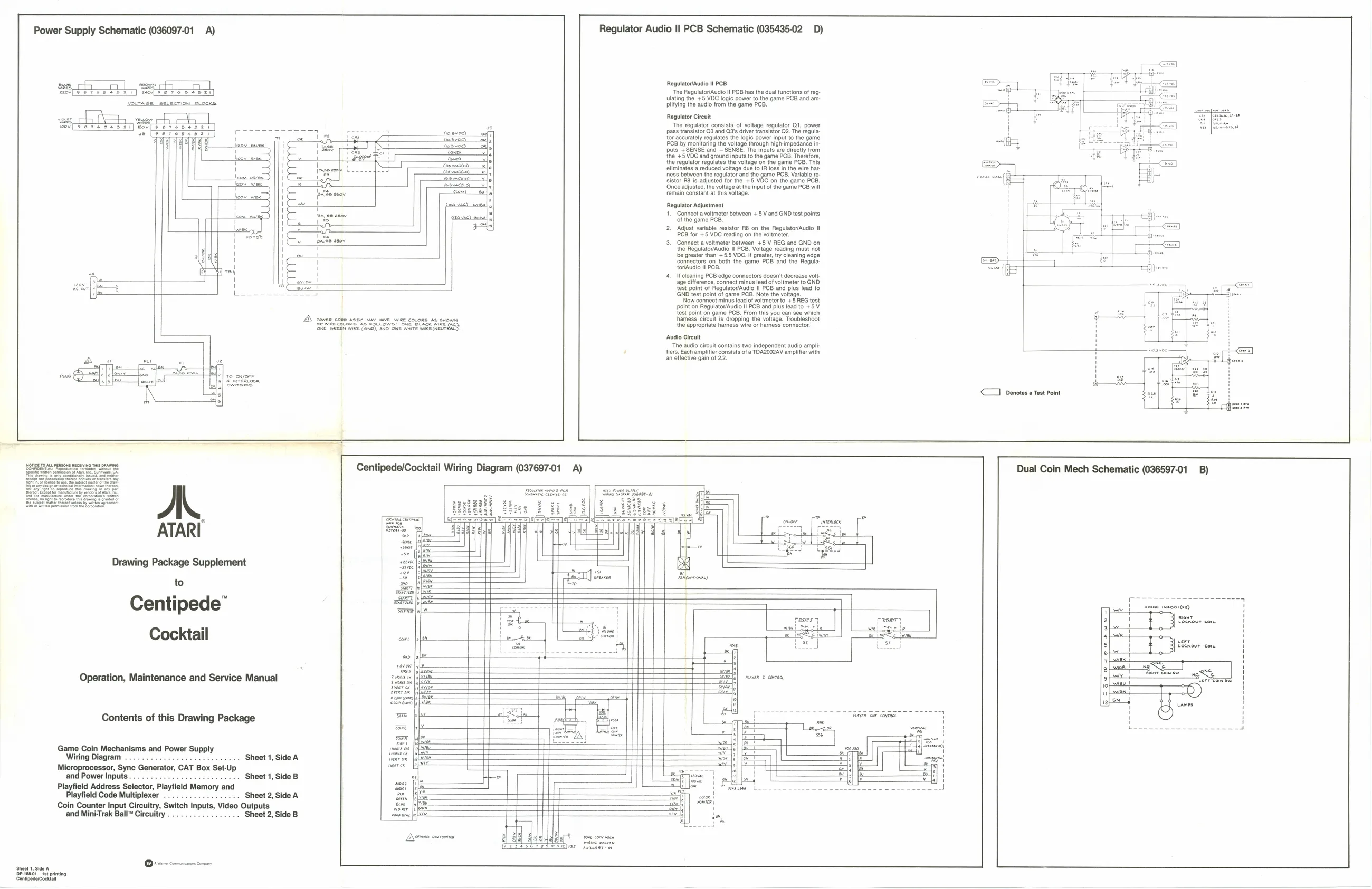
Power Supply Schematic (036097-01 A)
2 Sor| fee
DD sowee cone nosy Ar nave WIRE COLORS AS sxown Gre SeeeN ike Cen}, AND ONE miTe Wik (NEUTEALD,
AL
ATARI
Drawing Package Supplement
to
Centipede”
Cocktail
Operation, Maintenance and Service Manual
Contents of this Drawing Package
Game Coin Mechanisms and Power Supply Wiring Diagram . Sheet 1, Side A Microprocessor, Sync Generator, CAT Box Set-Up and Power Inputs . Sheet 1, Side B Playfield Address Selector, Playfield Memory and Playfield Code Multiplexer -++ Sheet 2, Side A Coin Counter Input Circuitry, Switch Inputs, Video Outputs and MiniTrak Ball™ Circuitry ........ 0. sce. ‘Sheet 2, Side B
‘Sheet, Side A Deriee fat piting ‘Centipedicocktal zoe) eon zal Regulator Audio Il PCB Schematic (035435-02 D)
Rogulator/Audio Il PCB. ‘The Regulator/Audio Il PCB has th Ulating the +5 VDC logic power to plitying the audio from the game PCE Inctions of reg PCB and am-
Regulator Circuit The regulator consists of voltage regulator Q1, power pass transistor Q3 and Q3's driver transistor Q2. The regula tor accurately regulates the logic power input to the game PCB by monitoring the voltage through high-impedance inputs +SENSE and ~ SENSE. The inputs are directly from the +5VDC and ground inputs tothe game PCB. Therefore, the regulator regulates the voltage on the game PCB. This eliminates a reduced voltage due to IR loss in the wire harness between the regulator and the game PCB. Variable resistor RB is adjusted for the +5 VDC on the game PCB. ‘Once adjusted, the voltage atthe input of the game PCB will remain constant at this voltage.
Regulator Adjustment
- Connect a voltmeter between +5 V and GND test points of the game PCB.
- Adjust variable resistor R& on the Regulator/Audio I PCB for +5 VDC reading on the voltmeter.
- Connect a voltmeter between +5 V REG and GND on the Regulato”/Audio Il PCB. Voltage reading must not 'be greater than +5.5 VDC. It greater, try cleaning edge ‘connectors on both the game PCB and the RegulatovAuaio Il PCB. If cleaning PCB edge connectors doesn't decrease volt: age dtference, connect minus lead of voltmeter to GND test point of Regulator/Audio Il PCB and plus lead to GND test point of game PCB. Note the voltage. Now connect minus lead of voltmeter to +5 REG test ppoint on Regulator/Audio ll PCB and plus lead to +5 V {est point on game PCB. From this you can see which hhamess circuit is dropping the voltage. Troubleshoot the appropriate harness wire or harness connector. ‘Audio Circuit ‘The audio circuit contains two independent audio ampli fiers, Each amplifier consists of a TOAZOO2AV amplifier with an eifective gain of 22.
Centipede/Cocktail Wiring Diagram (037697-01 A)
raver 2 cnTRa. <1 denotes a Tost Point
Dual Coin Mech Schematic (036597-01 B)
pigBe msoor (x8)