Centipede Caberat DP-189-1st-01A
Centipede (revision 4) (Atari, 1980) · Drawing Package · 1 pages · original scan
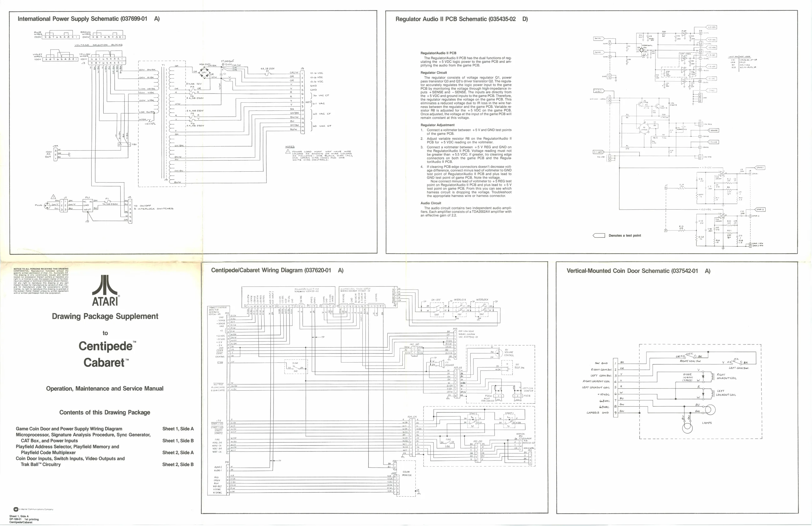
Intemational Power Supply Schematic (037699-01 A) Regulator Audio Il PCB Schematic (035435-02 D)
Sars CT Oo ees fal vownee segcrion eLocKs,
| oer | PS | yewaw | Regulator/Audio Il PCB |
ea tet ety ev[eeteeebes “Te Regulatr/Auco Il PCB has the dual functions of reg-
| uo | (etessser | poe eee | Lesa | ulating the +5 VOC logic power to the game PCB and am- |
3 4 Or5eConw plifying the audio from the game PCB. oar Regulator Creat oes The regulator consists of volage regulator 1, power ree pass tanaisto 09 and G8 caver ansator G2, Th ropa pa {er accuraoly epustes the togie power Input io te game < C8 by menitonng the vltago though hghmpedanee in fits YSENBE ard “SENSE The nputogre ect rom Joe weer the +5 VOC and ground inputs ioe ge PCB, Theetore, the ‘epuatorragultes th wage on he game POD. Tis ae tlimirats a reducod voltage Gus toh loss nine we ar toss batweon the fogultey and the game BCD, vandble te sistor RB is adjusted for the +5 VOC on the eo vac er ‘Once adjusted, the voltage atthe input of the g remain constant at this voltage. jame 12 PCE wil Je vac er Regulator Adjustment
- Connect a voltmeter between +5 V and GND test points ofthe game PCB.
- Adjust variable resistor Ron the Regulator/Audi I PGB for #8 VDC reading on the voltmeter. sons 3. Connect a voltmeter between +5 V REG and GNO on Need coe roe oS ers cr the RegulatorAuclo II PCB. Voltage reading must nat SO ea, Sr es es be greater than +55 VDG. I greater ry cleaning edge eee Se Connectors on both the game PCB and the Hegule torAudlo il PCB
| 4. | Ifcleaning PCB edge connectors doesnt decrease vol | - | - | spies | co |
‘ge ciference, connect minus ead ot voltmeter to GNO test point of Regulator/Audio Il PCB and plus lead to i GND test point of game PCB. Note the voltage. " ‘Now connect minus lead of voltmeter to +5 REG test i point on Regulator/Audio il PCB and plus lead to +5 V test point on game PCB. From this you can see which hamess circle dropping the voltage. Tovbleshoot
| aA» | of | we | tho appropiate hemese wie or hamess connector, |
bre
‘Audio Cireuit The audio circuit contains two independent audio amy fiers. Each amplifier consists of a TDA2002AV amplifier an effective gain of 22. faaict
<7 Denotes a test point
| pes | : | Centipede/Cabaret Wiring Diagram (037620-01 | A) | Vertical-Mounted Coin Door Schematic (037542-01 | A) |
Drawing Package Supplement
to
| Centipede | (a | =o | a | 1 | |
| Cabaret | = | ae | - | Tce | |
| wr conse | |2 | H | 1 | ||
| Operation, Maintenance and Service Manual | cas | Gale | 1 | eer | ! |
| swvoe | [oY | : | | cocnourcou. | \ | |
| eau | [7/4 | “ | ! | ||
| esc | |S a | 4 | Be |
Contents of this Drawing Package a mses one fpf | 7 <0)
| y | . | canes | i | |||||
| Game Coin Door and Power Supply Wiring Diagram | Sheet 1, Side A | 1 | i | |||||
| Microprocessor, Signature Analysis Procedure, Sync Generator, | C | Hy | 3 | |||||
| CAT Box, and Power Inputs | Sheet 1, Side B | SS | SS | TSH | 1G PQS ZO | OF A | en can | rr |
Playfield Address Selector, Playtield Memory and Playfield Code Multiplexer ‘Sheet 2, Side A Coin Door Inputs, Switch Inputs, Video Outputs and -
| Trak Ball™ Circuitry | Sheet 2, Side B | wor Phe | =| |