Sente SACMAN Field Conversion Kit for Upright (M051-00139-A009)
SAC-MAN (Bally Sente) · Field Conversion Kit · 54 pages · 27 sections · original scan
FIELD CONVERSION KIT FOR VIDEO GAME UPRIGHT MODEL
SSS SE =" TM.
10601 W Belmont Avenue Franklin Park. Illinois 60131 USA Phone (312) 451-9200 Cable Address MIDCO TelexNo 72-1596
MO051—00139-A009
THIS GAME MUST BE GROUNDED. FAILURE TO DO SO MAY RESULT IN DESTRUCTION TO ELECTRONIC COMPONENTS.
ELECTRICAL BULLETIN: FOR ALL APPARATUS COVERED BY THE CANADIAN STANDARDS ASSOCIATION (CSA) STANDARD C22.2 NO. 1, WHICH EMPLOYS A SUPPLY CORD TERMINATED WITH A POLARIZED 2-PRONG ATTACHMENT PLUG.
ATTENTION: POUR PREVENIR CHOCS ELECTRIQUES NE PAS UTILISER CETTE FICHE POLARISEE AVEC UN PROLONGATEUR. UNE PRISE DE COURANT OU UNE AUTRE SORTIE DE COURANT, SAUF SI LES LAMES PEUVENT ETRE INSEREES A FOND SANS EN LAISSER AUCUNE PARTIE A DECOUVERT.
Inwiles You To Use
OUR TOLL FREE NUMBERS FOR SERVICE INFORMATION CONCERNING THIS GAME, OR ANY OTHER BALLY/SENTE™ GAME YOU NOW HAVE ON LOCATION.
CALL US FOR PROMPT, COURTEOUS ANSWERS TO YOUR PROBLEMS
ANSWERS TO YOUR PROBLEMS.
Video - Continental U.S. 800-323-7182
10601 West Beimont Averiue Franklin Park, Illinois, 60131 phone (312) 451-9200
®COPYRIGHT MCMLXXXV!I BY BALLY SENTE INC. ALL RIGHTS RESERVED
NO PART OF THIS PUBLICATION MAY BE REPRODUCED BY ANY MECHANICAL, PHOTOGRAPHIC, OR ELECTRONIC PROCESS, ORIN THE FORM OF A PHONOGRAPHIC RECORDING, NOR MAY IT BE TRANSMITTED, OR OTHERWISE COPIED FOR PUBLIC OR PRIVATE USE, WITHOUT PERMISSION FROM THE PUBLISHER. THIS MANUAL IS FOR SERVICE USE ONLY, AND NOT FOR GENERAL DISTRIBUTION. FOR PERMISSION REQUESTS, WRITE BALLY/SENTE INC., 10601 W. BELMONT AVE., FRANKLIN PARK, IL 60131
Printed in U.S.A.
TABLE OF CONTENTS
I. Sac-man System Conversion Information
- Safety, Warnings and Cautions ............ nde eavoceess ot means weel- 1
- Sac-man Mainframe Conversion Procedure 3
- Ground Strapping Procedure ..........+ 4
- Sac-man Game Conversion Instructions . 7
- Decal Instructions .......cceeeecececeseceeecnvece 9
Il. Illustrated P.C.B. Parts ListS ......cceceeeseceeeee nr ny os |
- PCB Assembly, CPU, SAC 1 ...ccceccceseeceeesecvarace o 22-2
- PCB Assembly, Audio, 6VB ("B" Version P.C.B. Bal 2-5
- PCB Assembly, Trackball Converter ........ 2- 8
- PCB Assembly, Linear Power Supply ..... 2-9
- PCB Assembly, Cartridge, SAC-1, Generic ..... eee 2-11
- PCB Assembly, 128K Cartridge, SAC-1, Generic .....++... 2-12
- PCB Assembly, 128K Cartridge with Secure, SAC-1, Generic .... 2-13
- PCB Assembly, 256K Cartridge with Ultra Secure, SAC-1, Generic 2-14
- PCB Assembly, Audio, 6VB ("C" Version P.C.B.) ..sccceesececececere 2-15
III. P.C.B. Schematics ....... Sede cece eect nn ce cere ete c ee teee cesses eeseesees 3-1
- Schematic for PCB Assembly, CPU ...cscsceccseescuecetceeveeesceees 3- 2
- Schematic for PCB Assembly, Audio 6¥B ("B" Version P.C.B.) .. 3-12
- Schematic for PCB Assembly, Trackball Converter . 23-15 4, Schematic for PCB Assembly, Linear Power Supply
- PCB Schematic, Cartridge, SAC-1, Generic .......
- PCB Schematic, 128K Cartridge, SAC- 1, Generic ....... .
- PCB Schematic, 128K Cartridge with Secure, SAC-1, Generic wee eree e321
- PCB Schematic, 256K Cartridge with Ultra Secure, SAC-1, Generic ..3-22
- PCB Schematic, Audio, 6VB, ("C" Version P.C.B) ..cecseeeeseseaeees 3-23
LIST OF ILLUSTRATIONS
Figure A. Sac-man Grounding Procedure ......cceeeccccecceceescscereeeunees 1-5 Figure B. Sac-man Grounding Procedure (Cont'd.) . 1- 6 Figure C. CPU Board/Option Switches ........ 1- 8 Figure D. Decal Instructions .....cecccereecerererecenrensnccseeteeeses 21-9
-i-
The parts contained in this field conversion kit must be installed without deviation from the instructions contained in this manual and kit. Failure to follow these instructions in every detail may result in the creation of illegal interference to radio and TV reception.
BALLY SENTE has verified that this field conversion kit, when installed in the game(s) specified in this manual, complies with the requirements in Part 15 of the FCC rules for a Class A computing device. Operation of this equipment in a residential area may cause unacceptable interference to radio and TV reception, requiring the operator to take whatever steps are necessary to correct the interference.
BALLY SENTE will not be responsible for incomplete or improper conversions, or installation ina game for which this field conversion kit is not intended. If this field conversion kit’ is installed in a game that is not specified in this manual or in a previously converted game, the operator is required to take whatever steps are necessary to insure compliance with the requirements in Part 15, Subpart J, of the FCC Rules for a Class A computing device.
Please be advised that when converting a game it is advisable that all former trademark and copyright registrations be removed in the conversion process.
SPECIAL NOTE:
THE PARTS REMOVED, WHILE MAKING MODIFICATIONS
EXPLAINED IN THIS MANUAL, WILL NOT BE REUSED
The word "discard", as used in this manual, makes reference to this fact. All parts removed may be considered usable for other purposes.
-ii-
I. SAC-MAN SYSTEM CONVERSION INFORMATION
SAFETY
The following safety hints apply to all game operators and service personnel. Specific warnings and cautions will be found throughout this manual where they apply.
WARNINGS
AC POWER CONNECTION. Before connecting the game to the AC power source, verify that the proper voltage-selection plug is installed on the electronic chassis assembly.
PROPERLY GROUND THE GAME. Customers may receive an electrical shock if this game is not properly grounded! To avoid shocks, do not plug in the game until it has been inspected and properly grounded. Sente game should only be plugged into a grounded 3-wire outlet. Customers may receive an electrical shock if the control panel is not properly grounded!. After servicing any parts on the panel, check that the grounding wires are secure. Only then should you lock up the game.
DISCONNECT POWER DURING REPAIRS. To avoid electrical shock, disconenct the game from the AC power source before removing or repairing any part of the game. When removing or repairing the monitor, extra precautions must be taken to avoid electrical shock because high voltages may exist within the display circuitry and cathoderay tube (CRT) even after power has been disconnected. Do not touch internal parts of the display with your hands or metal objects! Always discharge the second anode from the CRT before servicing this area of the game. To discharge the CRT: attach one end of a large, well-insulated, 20-kY jumper to ground. Momentarily touch the free end of the grounded jumper to the anode by sliding it under the anode cap. Wait two minutes and discharge the anode again.
USE THE PROPER FUSES. To avoid electrical shock, use replacement fuses which are specified in the parts list for this game. Replacement fuses must match those replaced in fuse type, voltage rating, and current rating. in addition, the fuse cover must be in place during game operation.
HANDLE FLUORESCENT TUBE AND CRT WITH CARE. If you drop a fluorescent tube or CRT and it breaks, it may implode! Shattered glass can fly eight feet or more from the implosion.
PROPERLY ATTACH ALL CONNECTORS. Make sure that the connectors on each printedcircuit board (PCB) are properly plugged in. If they do not slip on easily, do not force them. A reversed connector may damage your game and void the warranty.
1-1
1-2
OLD UPRIGHT GAME TO SAC-MAN MAINFRAME CONYERSION PROCEDURE
To convert your OLD UPRIGHT GAME to a SAC-MAN mainframe is not a difficult operation. Just follow each step and the illustrations given in each figure in this general information manual and also the NEW GAME ASSEMBLY OF INFORMATION SHEETS. Also refer to the wiring diagram(s) provided in the NEW GAME ASSEMBLY OF INFORMATION SHEETS.
REMOVAL OF OLD GAME HARDWARE
- Turn the power off to your game and disconnect it from its wall outlet.
- Unlock and open Coin Mech door.
- Unlock and remove rear access door.
- Disconnect and remove all OLD GAME P.C. Boards and their mounting hardware and discard.
- Remove OLD GAME'S attract Art (Header) & discard.
Wote: Before removing old cabling, mark cable locations in game cabinet. Most of the corresponding new cabling (except for Master Cable Harness) should be routed as old cabling was unless noted otherwise. Therefore, leave all cable clamps where they are in game cabinet until new cabling is to be installed.
At this point, please refer to NEW GAME ASSEMBLY OF INFORMATION SHEETS to complete OLD GAME HARDWARE removal procedure.
INSTALLATION OF SAC-MAN HARDWARE
1-3
SAC-MAN FIELD CONVERSION KIT GROUND STRAPPING PROCEDURE FOR FIELD CONVERSIONS
Referring to Figure A, secure 3 large yellow Ground Straps to Transformer Power Chassis (as shown in figure) using 6-32 x 5/32" self-threading screw in a small hole in chassis.
Secure shortest yellow Ground Straps of three to CPU Board Mtg. Plate (back side) as shown in Figure A using 6-32 hex nut fastened to 6-32 X 1 phil. screw.
Secure shorter of two remaining Ground Straps to Power Supply and Audio Board Mtg. Plate as shown in Figure B using 6-32 hex nut fastened to 6-32 x 3/4" phil. rnd. hd. screw.
Route long yellow Ground Strap up to the Coin Door area. Locate green/white #22 AWG ground wire (part of Master Cable Harness). Secure these along with a very short yellow Ground Strap and a 7" long black Ground Strap to weld stud on Coin Door frame (located on Coin Door's hinge side). Secure the two straps and wire with a 10-32 hex nut.
Secure very short yellow Ground Strap to any stud or bolt on Control Panel. Secure strap to inside of Control Panel with nut already being used with stud or bolt.
7" Black Ground Strap is secured to Coin Door in one of two ways as follows:
A. Remove screw securing any metal component to Coin Door. Place other end of the black Ground Strap between component and inside (bare metal area) of Coin Door and secure using the same screw.
B. Use any available screw to secure end of black Ground Strap to inside (bare metal area) of Coin Door.
The Monitor Assembly is to be grounded as follows: Locate a small hole (near the A.C. outlet) on Monitor Assembly's Chassis. There may or may not be a 6-32 or 8-32 self-threading screw in that hole (depending on your original game's cabinet). If there is not, then use the #6-32 X 5/32" slotted (w/washer) thread forming screw to secure green ground wire (part of Monitor Cable Assembly) to Monitor Assembly's Chassis.
SAC-MAN GROUNDING PROCEDURE (CONT'D)
STEP 3: SECURE SHORTER OF 2 REMAINING YELLOW GROUND STRAPS TO P.8. & AUDIO BOARD MTQ, PLATE USING 6-32 HEX NUT FASTENED TO 6-32 x1 PHIL. SCREW.
TO COIN DOOR FRAME
P.8. & AUDIO BOARD MTQ. PLATE
MTQ, PLATE
TRANSFORMER POWER CHASSIS. STEP 1: SECURE 3 YELLOW GROUND STRAPS TO TRANSFORMER POWER CHASSIS WITH SELF THREADING SCREWS.
FIGURE A
1-5
SAC-MAN GROUNDING PROCEDURE
TO COIN DOOR FRAME
c.P.U, BOARD MOUNTING PLATE
STEP 2: SECURE SHORTEST OF 3 YELLOW GROUND STRAPS TO TO P.8. & AUDIO C.P.U. BOARD MTG, PLATE (BACK BOARD MTQ. PLATE SIDE) USING 6-32 HEX NUT FASTENED TO 6-32x1 PHIL. SCREW.
FIGURE B
1-6
SAC-MAN GAME CONVERSION INSTRUCTIONS
The following instructions will cover the conversion of games used in SAC-MAN mainframes. These instructions apply to the SAC-MAN mainframe converted from your OLD GAME. Additional instructions will be provided, when needed, for special conversions. Each new game conversion kit used in the SAC-MAN mainframe should contain the following material: 1 control panel insert assembly 1 attract art 1 game cartridge with ROMS 1 option switch setting/game description sheet 1 control panel schematic If a new game conversion kit does not contain all of this material or if the material included is not for the correct game, contact your distributor.
NAOPWNE SIMPLIFIED INSTRUCTIONS
Power off SAC-MAN unit. Change attract art. Change control panel insert. Change game cartridge. Check option switch settings. Power on SAC-MAN unit. Play game.
BE SURE TO SAVE GAME CARTRIDGE, CONTROL PANEL INSERT, AND ATTRACT ART FOR REUSE.
DETAILED INSTRUCTIONS
To Change Attract Art: 1.
2. 3.
4. 5. 6. Remove bolts holding in Attract Retaining Bracket located at top front of cabinet. Remove Attract Retaining Bracket. Slide Attract Glass up and out of cabinet. Remove old Attract Art from back of Attract Glass. Replace with new Attract Art by centering and taping it to clear area of Attract Glass backside. Slide attract Glass containing new art back into cabinet. Replace and secure Attract Retaining Bracket. Clean front of Attract Glass.
To Change Panel Insert: 1. 2. 3. Power off SAC-MAN unit using switch located on top of cabinet. Unlock and open Coin Mech door at front of cabinet. Release the Control Panel Latches (at each end of the Control Panel) located inside cabinet above the Coin Mech door.
1-7
To Change Panel Insert: 4.
9. 10. ll. If your Control] Panel is connected to the cabinet with a continuous hinge, swing the panel up and out. If your Control Panel is NOT connected to the cabinet with a continuous hinge, lift the panel up. Disconnect cabling of Control Panel from Master Cable Harness by pulling plugs apart. Control Panel without continuous hinge is now loose. Remove bolts from Control Panel insert and remove Control Panel insert from Control Panel. Place new Control Panel Insert in Control Panel and secure with bolts. Replace Control Panel after plugging Control Panel Harness into Master Cable Harness. Latch Control Panel into place. Close and lock Coin Mech door. Power on SAC-MAN unit using switch on top to left rear of cabinet. Play game to check if all switches and controls are operating properly.
To Change Game Cartridge: 1. 2. 3. Power off SAC-MAN unit using switch located on top of cabinet. Unlock and remove rear access door. Find interlock Switch located on right wall of cabinet just inside rear access door. This switch may be used to power unit on and off in place of switch at top | rear of cabinet. To power unit on, pull out plunger of switch to its "extended" position. To power off, push plunger back in. Slide old Game Cartridge out of C.P.U. Board Assembly (see Figure C). Slide new Game Cartridge between runners to plug into C.P.U. Board Assembly. Be sure Game Cartridge is securely plugged in. ROMS on the Game Cartridge should be facing to the left as you look into the cabinet through the rear access opening. Check game option switch settings. Close and lock rear access door. Power on SAC-MAN unit using switch on top (to left rear) of cabinet. Play game to test if unit is working properly.
CARTRIDGE,
GAME [0 Sv IND. ‘BOTTOM
Figure G. CPU Board/Option Switches
1-8
FIGURE D
Cabinet T-Molding
Insert blade between edge of
side panel and T-molding. Follow edge and cut away excess.
Bottom of Decal
TYPICAL MOUNTING SUGGESTIONS Mount the decal either on a horizontal (A) or ona (B) angle. The bottom of the "gente" should always be centered on the cabinet. Angled
DECAL INSTALLATION INSTRUCTIONS
IMPORTANT NOTE:
READ THE FOLLOWING INSTRUCTIONS THROUGH COMPLETELY AT LEAST ONCE BEFORE ATTEMPTING TO
INSTALL THE DECAL(S) THEY CONCERN! !
THE DECAL(S) ARE COMPOSED OF THREE (3) PARTS: 1)A HEAVY WAXED BACKING SHEET WHICH COVERS THE STICKY SIDE OF THE DECAL, 2) THE DECAL ITSELF, AND 3)A THIN MASKING SHEET WHICH IS ON THE FRONT SIDE OF THE DECAL TO PROTECT IT AND TO AID IN ITS INSTALLATION.
ee ee Ke & * ® * TO INSTALL THE DECAL(S), PROCEED AS FOLLOWS: * * * * * # # RR RH
1. BE SURE THE AREA WHERE YOU ARE GOING TO APPLY THE DECAL IS CLEAN AND FREE OF ALL DIRT, GREASE, AND GRIME.
USING ANY SPRAY-ON GLASS CLEANER, THOROUGHLY WET DOWN THE AREA WHERE YOU INTEND TO PUT THE DECAL.
REMOVE THE HEAVY WAXED BACKING SHEET FROM THE DECAL BY POSITIONING IT FACE UP ON A FLAT SURFACE; GOING TO ANY CORNER; AND BENDING THIS CORNER UP SLIGHTLY TO SEPARATE THE DECAL AND THIN MASKING SHEET FROM THE HEAVY WAXED BACKING SHEET.
SLOWLY AND CAREFULLY PEEL THE HEAVY WAXED BACKING SHEET AWAY FROM THE DECAL AND MASKING SHEET.
PLACE THE DECAL ON THE GAME CABINET OVER THE WET GLASS CLEANER YOU JUST APPLIED. (THIS WILL ALLOW A SMALL AMOUNT OF FINAL POSITIONING TO BE DONE AFTER THE DECAL 1S APPLIED TO THE GAME CABINET.)
SMOOTH THE DECAL.
ALLOW THE DECAL TO BECOME FIRMLY AFFIXED TO THE GAME BEFORE PROCEEDING TO THE NEXT STEP.
II. ILLUSTRATED P.C.B.
PARTS LISTS
see oem AN
SEE DETAIL B
| a
MOTES: UNLESS OTHERW
['] Yi (ITEM 90) TO HAVE 20 AWG WIRE WRAPPED
AROUND BODY AND SOLDERED IN HOLES PROVIDED. ISE SPECIFIED 25, REV] ECONO, REVISIONS DESCRIPTION
# ROW Tres 2Pl Ca) 1990 | SEETES TEM TS" ADDED TEM SS SHG QTY ON ITEMS 18.19
(REF)(88 YY
cera AN (1)(Rer) SCALE? 2/1
PIN |
- REF)
a a 5 =
CREF)
DETAIL B
SCALE 2/1
P WES 2ftios MO51-00C52-C013 DESCRIPTION/MATERTAL
[OOO=BOIH1O_f ascuus DRAWING [or earne. x DAWN BY Date SURFACE FINISH USED ON
SEE LIM Lifeere */2/aq Lip bene th PCB ASSEMBLY , CPU, SAC-I
i “iB COIDNBWHH NERMEPRPEWRENWw
DWIPRPRPNEN UPR RH ar urN
Nw
Be PCB ASSEMBLY, CPU (006-8001-10-0C) (M051—00C52-C013) PARTS LIST - SHEET 2 of 4
PART NO.
007-8001~-01-0C
200-0039-01 200-0040-01 200-0041-01 200-0042-01 200-0043-01 200-0044-01 200-0075-01 200-0045-01 200-0046-01 200-0047-01 200-0048-01
200-0052-01 200-0076-01 200-0053-01
200-0032-01 200-0055-01
200-0056-01 200-0057-01
200-0078-01 200-0058-01 200-0059-01 200-0077-01 200-0060-01
200-0061-01 200-0062-01 200-0063-01 200-0064-01 200-0065-01 200-0066-01 200-0067-01 200-0068-01 200-0069-01
200-0070-01 200-0082-01
210-0005-01 230-0007-01 REFERENCE
U1IF,14D,14C U14E,15B U16C U13E U8F,9F,14B U17B U10H ul6éD U13F,14F ULOF U17D,U20E
U12C,13C Ul1H UL0B,11B,15C,17G, 18G U19A,15D,19E U18B,20B,12E,18E, 17E,16E,15F U19B U11D,11C, 26,36, 46,56 U12A U9H U1IA U11G U10C,10D, 9D, 9C, 1lE
U17A,15A U1L6A U12G,18A U1OF U1OE UL2F U2E-6E,1F,2F U12B,13B,13A U3F ,4F,5F,6F,13D, 12D U9E,14A,10A U20A,U16G
U18D ULSE DESCRIPTION
PCB, FABRICATION, CPU,SAC-1
IC,DIG, TIL, 74LS00,NAND GATE IC,DIG, TIL, 74LS02,NOR GATE IC,DIG, TTL, 74LS04,HEX INVERTER IC,DIG, TTL, 74LS20,4-IN NAND IC,DIG, TTL, 74LS32,OR GATE IC,DIG, TIL, 74LS74,DUAL D F/F IC,DIG, TTL, 74LS86,QUAD X-OR IC,DIG, TTL, 74LS96,5 BIT SHIFT IC,DIG, TTL, 74LS109,DUAL JK F/F IC,DIG, TTL, 74LS125,QUAD BUFFER IC,DIG, TTL, 74LS138,3-8 DECODER
IC,DIG, TTL, 74LS163,4 BIT COUNT IC,DIG, TIL, 74LS164,8 BIT SHIFT IC,DIG, TTL, 74LS174,HEX D F/F
IC,DIG, TTL, 74LS175,QUAD D F/F IC,DIG, TIL, 74LS244,8TS BUFFER
IC,DIG, TIL, 74LS245,8 BUS XCVR IC,DIG, TIL, 74LS253,DATA SELECT
IC,DIG, TTL, 74LS257,4 2-1 MUX IC,DIG,TIL,74LS259,8 BIT LATCH IC,DIG, TTL, 74LS273,OCTAL D F/F IC,DIG, TIL, 74LS299,8 BIT SHIFT IC,DIG, TTL; 74LS374,OCTAL D F/F
IC,DIG, TIL, 74S00,NAND GATE IC,DIG, TTL, 74S02,NOR GATE IC,DIG, TTL, 74S04,HEX INVERTER IC,DIG, TIL, 74S08,AND GATE IC,DIG, TTL, 74S32,OR GATE IC,DIG, TTL, 74S74,DUAL D F/F IC,DIG, TTL, 74S151,8-1 MUX IC,DIG,TTL,74S157,4 2-1 MUX IC,DIG, TTL, 74S163,4 BIT COUNT
IC,DIG, TTL, 74S174,HEX D F/F IC, DIG, TTL, 74S86 ,QUAD X-OR
IC,DIG,CMOS, 4049UB,HEX INVERTER IC,DIG,NOV RAM,X 2212,256 X 4 PCB ASSEMBLY, CPU (006-8001-10-0C) (M051—00C52-C013) PARIS LIST - SHEET 3 of 4
| QTy. | PART NO. | REFERENCE | DESCRIPTION | |
| 44 | 3 | 240-0003-01 | U18F,17F,16F | IC,DIG,RAM,2148,1K X 4,70NS |
| 45 | 32 | 240-0004-01 | U1A-BA, 1B-8B, | IC, DIG, RAM,4116,16K X 1,150NS |
1C-8C,1D-8D
| 46 | 1 | 260-0002-01 | U8H | IC,DIG, INT, ULN2003, DRIVER |
| 47 | 1 | 015-8001-10-0B | U20F | PAL, SAC=1 |
| 48 | 1 | 250-0010-01 | U9G | IC,DIG,MPS,68B50,ACIA, .75MHZ |
| 49 | 1 | 250-0006-01 | U17C | IC,DIG,MPU, 68A09E |
| 50 | 1 | 260-0030-01 | U6G | IC,SP,,ADC 8 BIT,ADC0809 |
| 51 | 1 | 320-0006-01 | cls? | CAP, MIC, RAD, 12PF,500V, 5% |
| 52 | 1 | 320-0007-01 | C158 | CAP,MIC,RAD, 100PF ,500V,5% |
| 53 | 172 | 300-0009-01 | C1,3,5,7,9,11,13, CAP,CER,AXL,0.1UF,50V, 208 |
15,17-95,97,98, 100,102,103,105, 106,108,109,111, 112,114,115,117, 118,120,121-156, 159-185,190-195
| 54 | 2 | 340-0015-01 | C96,186 | CAP, ELEC, AXL, 1.OUF ,63V,50/-10% | |
| 55 | 2 | 340-0011-01 | C187,C188 | CAP, ELEC ,AXL, 100UF ,16V,50/-10% | |
| 56 | 1 | 340-0018-01 | c189 | CAP, ELEC, AXL, 470UF | ,6.3V,50/ |
| 57 | 8 | 310-0013-01 | C2,6,10,14,101, | CAP,TAN,AXL,2.2UF,10V, 20% |
107,113,119
| 58 | 8 | 310-0014-01 | C4,8,12,16,99, | CAP, TAN ,AXL,4.7UF,20V, 20% |
104,110,116
| 59 | 4 | 460-0015-01 | RP11,RP13,RP15, | RES,PAK,SIP,8 PIN,4X,33 OHM |
RP16
| 60 | 2 | 460-0016-01 | RP12,RP14 | RES, PAK,SIP,10 PIN,5X,33 OHM |
| 62 | 1 | 400-1500-01 | R63 | RES ,CF,1/4W,5%,150 OHM |
| 63 | 1 | 400-2200-01 | R29 | RES ,CF,1/4W,5%,220 OHM |
| 64 | 3 | 400-4700-01 | R32-34 | RES,CF,1/4W,5%,470 OHM |
| 65 | 37 | 400-1001-01 | R7,8,9,11,14,15, RES,CF,1/4W,5%,1K OHM |
18-21,27,28,35-57 62,64
| 66 | 1 | 400-2701-01 | R12 | RES,CF,1/4W,5%,2.7K OHM |
| 67 | 6 | 400-4701-01 | R13,31,58-61 | RES,CF,1/4W,5%,4.7K OHM |
| 68 | 2 | 400-1002-01 | R26, 30 | RES,CF,1/4W,5%,10K OHM |
| 69 | 2 | 400-1003-01 | R16,17 | RES ,CF,1/4W,5%,100K OHM |
| 70 | 5 | 460-0011-01 | RP4-8 | RES,PAK,DIP,16 PIN, 8X,2.2K OHM |
| 7 | 2 | 460-0012-01 | RP9, 10 | RES, PAK,SIP,10 PIN,9X,470 OHM |
| 72 | 1 | 460-0014-01 | RP3 | RES,PAK,SIP,8 PIN,7X,1.0K OHM |
| 73 | 2 | 460-0013-01 | RP1,2 | RES,PAK,SIP,10 PIN,9X,10K OHM |
| 74 | 1 | 400-2700-01 | R1O | RES ,CF,1/4W,5%,270 OHM |
| 76 | 1 | 510-0019-01 | UG | SOCKET, IC, 24P, LOW PROF,PC |
| 77 | 1 | 510-0020-01 | U6G | SOCKET, IC, 28P, LOW PROF , PC |
| 78 | 1 | 510-0021-01 | U17C | SOCKET, IC,40P, LOW PROF,PC |
2-3
2-4 PCB ASSEMBLY, CPU (006-8001-10-0C) (M051-00C52-C013) PARTS LIST - SHEET 4 of 4
| ITEM | ory. | PART NO. | REFERENCE | DESCRIPTION |
| 82 | 1 | 550-0063-01 | J22 | CONN, AMP 1-102589-7 |
| 83 | 1 | 500-0016-01 | LL | INDUCTOR, FER ,AXL, 100UH, 108 |
| 84 | 1 | 100-0002-01 | CRI | D10,SI,10MA,75 PIV,IN914 |
| 87 | 4 | 120-0003-01 | Q1,2,3,4 | XSTR,SI,NPN, 2N3904 |
| 88 | 1 | 260-0011-01 | VRI | 1C, LIN, VR,7905,5V NEG |
| 90 | 1 | 820-0004-01 | Yl | CRYSTAL, 20.000MHZ |
| 91 | Z | 840-0036-01 | Dsl | OPT, DSP, LED, SNG, RED |
| 92 | 2 | 570-0036-01 | U1G,1H | SW,DIP,8 PST |
| 94 | 1 | 801-0440-06-01 | SCREW PH PH 4-40 xX 3/8" | |
| 95 | 1 | 812-0440-00-01 | NUT , HEX, 4-40 | |
| 96 | 1 | 822-0004-00-01 | WASHER, SPLIT LOCK #4 | |
| 97 | 1 | 800-00237-01 | Dsl | SPACER, LED |
| 102 | 2 | 200-0079-01 | U7F ,U16B | IC,DIG, TTL, 74F175,QUAD D F/F |
| 103 | 2 | 200-0080-01 | U7E,U9B | IC,DIG, TTL, 74F374,OCTAL D F/F |
NC REV
eS | REVISIONS DESCRIPTION PROTOTYPE PRODUCTION RELEASE ADDED NOTE 3, REVERSED POLARITY OF C8. ADDED 2 HEATSINKS, ITEMS 62 £ 70)
mete)
are. 183 SENTE TECHNOLO
ca
f ‘aooooo
FASTEN U40 (ITEM 53) TO HEATSINK (ITEM 62) , HEATSINK (ITEM TO), AND WITH HARDWARE (ITEM 66,67 & ©8 ) BEFORE SOLDERING TO PCB. APPLY HEATSINK COMPOUND TO HEATSINK (ITEM 62) 4 HEATSINK (ITEM 70) FRIOR TO MOUNTING.
SHORT PIN | TO PIN2 OF U2B, AND MOUNT c®@ AS SHOWN TO USE AMI 2688 (S837 EQUIV). (TEM ©9), MO51-00C52-B015 DESCRIPTION MATERIAL, RELEASED BY: WES /2/1'
“DIMENSIONS ARE IN INCHES. DO NOT SCALE [OOO-BOlI=1O | mvcues DEBATING NEXT ASSY NO. &E waa] oe i _——— USED ON 1289 Anvilwood Ave._Sunnyvale, CA 4089. i L fore “M/s ""bog ASSEMBLY, AUDIO, 6VB aa
Project eNcINeER |
PCB ASSEMBLY, AUDIO 6VB (006-8002-10-0B) (M051—00C52-B015) PARTS LIST - SHEET 2 of 4
DESCRIPTION
RES ,CF,1/4W,5%,1K OHM RES ,CF,1/4W,5%,68K OHM RES,CF,1/4W,5%,100K OHM RES ,CF,1/4W,5%,1.0M OHM RES, CF,1/4W,5%,330 OHM RES ,CF,1/4W,5%,2.0K OHM RES ,CF,1/4W,5%,4.7K OHM RES ,CF,1/4W,5%,47K OHM RES, CF,1/4W,5%,33 OHM RES ,CC,1/4W,5%,10M OHM RES ,MF,1/8W,1%,301K OHM RES ,MF,1/8W,1%,19.6K OHM RES ,MF,1/8W,1%,20.0K OHM RES ,MF,1/8W,1%,4.02K OHM RES ,MF,1/8W,1%,1.00K OHM RES ,MF,1/8W,1%,121 OHM RES ,MF,1/8W,1%,499 OHM RES ,MF,1/8W,1%,10.0K OHM
CAP, PES, RAD,0.001UF, 100V,10%
CAP, PST,AXL,0.002UF, 100V,5% CAP, PES,RAD,0.01UF,100V, 10%
CAP, PES, RAD, 0.033UF,100V 10%
CAP, CER, RAD, 33PF, 50V, 10% CAP, CER, RAD, 680PF, 50V,5%
CAP, CER, RAD, 0.1UF,50V, 20%
CAP, TAN, RAD, 1.0UF, 25V, 20%
| ITEM | Ory. | PART NO. | REFERENCE |
| 1 | 2 | 400-1001-01 | R1,R44 |
| 2 | 1 | 400-6802-01 | R3 |
| 3 | 5 | 400-1003-01 | R4,5,42,45,51 |
| 4 | 12 | 400-1004-01 | R6,7,/12,13 |
| 5 | 3 | 400-3300-01 | R8,9,11 |
| 6 | 6 | 400-2001-01 | R15,16,17,20,22,50 |
| 7 | 3 | 400-4701-01 | R25,41,46 |
| 8 | 2 | 400-4702-01 | R48,49 |
| 9 | 1 | 400-3307-01 | R43 |
| 10 | 1 | 401-1005-01 | R47 |
| ll | 6 | 450-3013-01 | R2,10,14,21,26,29 |
| 12 | 1 | 450-1962-01 | R40 |
| 14 | 1 | 450-2002-01 | R30 |
| 15 | 1 | 450-4021-01 | R31 |
| 16 | 1 | 450-1001-01 | R32 |
| 17 | 1 | 450-1210-01 | R35 |
| 18 | 1 | 450-4990-01 | R36 |
| 19 | 1 | 450-1002-01 | R39 |
| 21 | 12 | 330-0005-01 | C14,18,34,38,53, |
57,71,75,89,93,119,
| 22 | 6 | 330-0009-01 | C1,15,35 |
54,72,90
| 23 | 48 | 330-0006-01 | C2,5,6,7,9,16,23,25, |
26,27,28,29,30,36,43, 45,46,47,48,49,50,55, 62,64,65,66,67,68,69, 73,80,82,83,84,85,86, 87,91,98,100,101,102, 103,104,105,126,129,
| 24 | 20 | 330-0007-01 | C20,21,22,40,41,42, |
59,60,61,77,78,79,95, 96,97,113,114,123, 124,125
| 25 | 3 | 300-0011-01 | 112,116,134 |
| 26 | 7 | 300-0012-01 | C19,31,39,58,76,94, |
| 27 | 25 | 300-0002-01 | C3,4,10,12,17,24,32, |
37,44,51,56,63,74,81, 92,99,106,107,109, 110,111,115,117,128,
| 28 | 3 | 310-0012-01 | 127,131,132 |
| 29 | 3 | 340-0016-01 | C8,11,108 |
CAP, ELC, AXL, 2. 2UF,63V,50/ (006-8002-10-0B) (M051-00C52-B015) PARTS LIST — SHEET 3 of 4 PCB ASSEMBLY, AUDIO 6VB
| ‘Trex | Ory. | PART NO. | REFERENCE | DESCRIPTION |
| 30 | 6 | 340-0017-01 | C13,33,52,70,88,118 | CAP, ELC,AXL, OUF, 35V,50/ |
| 31 | 6 | 260-0033-01 | U1,6,11,16,21,31 | IC,SP,SOUND, SYNTH ,CEM, |
3394
| 32 | 5 | 210-0007-01 | 024,25,27,28,30 | IC,DIG,CMOS,4174B,HEX D |
E/F
| 33 | 6 | 210-0006-01 | U3,7,12,17,22,32 | IC,DIG,CMOS,4051B,8 CHAN |
MUX
| 34 | 1 | 210-0005-01 | U36 | IC,DIG,CMOS, 4049UB, HEX |
INVERT
| 35 | 1 | 260-0029-01 | U34 | IC,LIN,OPAMP,TL084 ,QUAD, |
JFET
| 36 | 1 | 260-0031-01 | U35 | IC,SP,DAC 12 BIT, 7541 |
| 37 | 1 | 260-0007-01 | U37 | IC, LIN, COMP, LM311N |
| 38 | 1 | 260-0037-01 | u33 | IC, LIN,OPAMP,TLO71,JFET, |
INPUT
| 39 | 1 | 210-0008-01 | u29 | IC,DIG,CMOS, 4503B,HEX TS |
BUFFER
| 40 | 1 | 260-0040-01 | u2 | IC,SP,NOISE SOURCE MM5837 |
| 41 | 1 | 200-0039-01 | u18 | IC,DIG, TTL, 74LS00 , NAND |
GATE
| 42 | 2 | 200-0041-01 | U8,19 | IC,DIG, TTL, 74LS04, HEX |
INVERTER
| 43 | 1 | 200-0043-01 | ul4 | IC,DIG, TTL, 74LS32,OR GATE |
| 44 | 1 | 200-0044-01 | u23 | IC, DIG, TTL, 741874, DUAL |
D E/F
| 45 | 1 | 200-0074-01 | u9 | IC,DIG,TTL,7493,4 BIT |
COUNT
| 46 | 1 | 200-0049-01 | u13 | IC, DIG, TIL, 74LS139, 2-4 |
DECODER
| 47 | 1 | 250-0007-01 | u4 | IC,DIG,MPU,Z-80A |
| 49 | 2 | 240-0005-01 | ul0,15 | IC, DIG,RAM, 6116, 2KX8, |
200NS
| 50 | 1 | 250-0008-01 | u20 | IC, DIG,MPS ,8253-5, TIMER |
| 51 | 1 | 250-0010-01 | U26 | IC, DIG,MPS, 68B50,ACIA |
«75MHZ
| 52 | 1 | 260-0027-01 | U38 | IC, LIN, VR, 337T , VARIABLE |
NEG.
| 53 | 1 | 260-0028-01 | u40 | IC,LIN, VR, 78MO5SCT,5V POS |
| 54 | 1 | 260-0008-01 | U39 | IC, LIN, VR, 7805,5V POS |
| 55 | 4 | 100-0006-01 | D1, 2,3,4 | DIO,GR, 50MA, 75PIV, IN34 |
| 56 | 1 | 550-0062-01 | J5 | CONN 10 PIN LOCKING |
09-74-1101
| 57 | 4 | 510-0019-01 | U10,15,20, 26 | SOCKET, IC, 24P, LOW PRO |
| 58 | 1 | 510-0020-01 | US | SOCKET, IC, 28P, LOW PRO |
| 59 | 1 | 510-0021-01 | U4 | SOCKET, IC, 40P, LOW PRO |
| 60 | 1 | 100-0002-01 | DS | D10,S1,10MA,75 PIV, IN914 |
ITEM Ory
61 1 62 1 63 1
64 2 65 1 66 3
67 3 68 3 69 1 70 HE PCB ASSEMBLY, AUDIO 6VB (006-8002-10-0B) (M051-00C52-B015) PARTS LIST - SHEET 4 of 4
. PART NO.
820-0003-01 850-0007-01 310-0015-01
400-2703-01 400-2700-01 801-0632-06-01
822-0006-00-01 816-0632-00-01 007-8002-01-0A 850-0008-01 REFERENCE:
XTL-1 HS-1 c120
R33,34 R52
HS-2 DESCRIPTION
CRYSTAL 8.000MHZ HEATSINK, THM-6070 CAP, TANT ,RAD, 47UF,15V, 20% RES ,CF,1/4W,5%,270K OHM RES ,CF,1/4W,5%,270 OHM SCREW PAN HD-PHIL 6-32X 3/8 WASHER SPLITLOCK 6 NUT ,HEX,SM PAT, 6-32 PCB, FAB, AUDIO, 6VB HEATSINK, THM-6071
REVISIONS DESCRIPTION PROTOTYPE REVISION 692] PRODUCTION RELEASE 19B4] AI-R4 WAS 2.2K 5 BK
REV A 006-8004-10 °
PCB ASSEMBLY, TRACKBALL CONVERTER (006-8004-010A) (M051-00B18-A007) PARTS LIST - SHEET 2 of 2
(TEM QTY. PART_NO. REFERENCE DESCRIPTION
1 007-8004-0 1-0A0 PCB,FAB,TRACKBALL CONVERTER
| 210-0003-01 | U2 | 1C,D\G,CMOS,4013B,DUAL D F/F |
| 210-0009-01 | ul | IC ,DIG,CMOS,4584B,HEX INV. |
| 260-0034-01 | U3 | IC,LIN,OP AMP,TLO82,DUAL JFET |
| 330-0007-01 | C3, C5 | CAP,PES,RAD,0.033UF ,100V, 10% |
| 310-0013-01 | c7 | CAP ,TANT,AXL,2.2UF ,10V,20% |
| 30-0009-01 | Cl, C2, C8 | CAP,CER,AXL,0. 1UF ,50V ,20% |
| 33-0008-01 | C4, C6 | CAP ,RES,RAD,O.10UF, 100V, 10% |
| 40-03301-01 | R1 - R4 | RES,CF,1/4W,5%,3.3K OHM |
| 40-01002-01 | R5, R8 | RES,CF,1/4W,5%,10K OHM |
| 40-0220-01 | R10, R7 | RES,CF,1/4W,5%,220K OHM |
| 40-0390-01 | R6, RO | RES,CF,1/4W,5%,39K OHM |
| 10-0000-01 | CRi, CR2 | DIODE,S!1,10MA,75P1V,1N914 |
| 55-0006 | JQ | CONN, 8P ,MOLEX ,09-74-108 1 |
| 55-00018-01 | J23 | CONN,PC,F,PINS,MLX 02-09-1134 |
| 55-0006 1-01 | J23 | CONN,CBL,6P ,RCP,MLX 03-09-1064 |
RELEASED BY: fi © 10 '3)< MO5 1-00B18-A007 DESCRIPTION/MATERIAL,
wom ro au reno SEE L/M Lifes (5/23 | SCR ASSEMBLY, fim “| TRACKBALL CONVERT!
Ea
DETAIL C TYPICAL 4PL (DI-D4) | SCALE! 2/1
| 27.@)
NOTES: UNLESS OTHERWISE SPECIFIED | APPLY HEATSINK COMPOUND (ITEM 60) ON BOTH SIDES OF INSULATOR (ITEM 78) AT Q! AND Q2, AND ON BOTH SIDES OF INSULATOR (ITEM 77) AT U2 AND U3. APPLY BETWEEN HEATSINK AND COMPONENT AT U4,US U6 ,DI,D2,D3 AND D4. ‘@) 2PL @® 2PL
2PL
- 3PL SCALE: 2/1 VIEW A-A TYPICAL 2PL (Q1,02)
DETAIL BL TYPICAL 2PL (U2, U3) SCALE? 2/1
RELEASED BY: WES 3 /; MO5 1-00C52-8017
110 [O000-8011-10 | asus Sr suneact pints — X= Ho PERCIVAL_ 9/13/84 = ENGINEER PCB ASSY, LINEAR pw] power sueeLy == 15) 006-8009-10-0B |62-9 scave|/| & NOTED | sueer_ | = SEE L/M
PCB ASSEMBLY, LINEAR POWER SUPPLY (006-8009-10-0B) (M051-00C52-B017) PARTS LIST — SHEET 2 of 3
(TEM
AYAUEWN— QTY. PART NO.
00 1-8076-01-0B
007-8009-10-0B
100-0008-01
105-0004-01
110-0004-01
120-0004-01
160-0004-01
260-0039-01 260-0042-01
260-0043-01
260-0044-01
260-0045-01
300-0002-01
300-0001-01
320-0007-01
340-0026-01 340-0027-01
340-0028-01
340-0028-01
340-0030-01
400-1000-01 400-1008-01
400- 1007-01
400-1501-01
400-2200-01 REFERENCE DESCRIPTION
D5-D18,020-D25
D1-D4
D19
Q1,Q2
SCR1
U4 ,U6 U2
u3
U5
ul
C6,C7,C12,C13,C15,C17, €20,C23,C25 024,026
co
C14,C16,C18,C22 c19,C21
C1A,C1B,C1C,C1D
€3,C4,C10,C11
C2,C5,C8,C27
R8,R16 R1,R2
R7,R11
R13,R10
R15 HEATS | NK ,E~368/#5555
PCB FAB, LINEAR PWR SPLY
D10,S1,3A,100 PIV,MR501
D10,RECTIFIER,16A, MUR1610 CT D10,ZEN,5.6V,20MA,!N752A
XSTR,S1,NPN, 2N3055
SCR,8A,50V,C122F1
IC,LIN,SP,TDA2002, AUD AMP IC,LIN,VR,MC7912,-12V, 3 POS IC, LIN, VR,MC7812,+12V, 3 POS IC,LIN,VR,MC7815,+15V, 3 POS IC,LIN,VR,MC1723,S1,MONO
CAP ,CER,RAD,.1MF,50V
CAP,CER,RAD, .022UF ,50V, 20% CAP ,MIC,RAD, 100PF ,500V,
CAP ,ELC,RAD, 10MF ,50V ,20% CAP,ELC,RAD,470MF, 16V, -10% ,+50% CAP, ELC,RAD,10.000MF, 16V +10%,-30% CAP,ELC,RAD ,6800MF,25V, -10% ,+30% CAP,ELC,RAD, 1000MF,50V, 20%
RES,CF,1/4W,5%,100 OHM RES,CF,1/4W,5%,1 OHM
RES,CF,1/4W,5%,10 OHM
RES,CF,1/4W,5%,1.5K OHM
RES,CF,1/4W,5%,220 OHM PCB ASSEMBLY, LINEAR POWER SUPPLY (006-8009-10-0B) (M051-00C52-B017) PARTS LIST - SHEET 3 of 3
| 1 TEM | Qty. | PART_NO. |
| 38 | 2 | 400-2208-01 |
| 40 | 1 | 400-2701-01 |
| 41 | 1 | 400-3900-01 |
| 42 | 1 | 400-4701-01 |
| 43 | 2 | 400-4707-01 |
| 44 | 1 | 480-0007-01 |
| 45 | 1 | 480-0008-01 |
| 46 | 3 | 410-2200-01 |
| 47 | 1 | 440-0508-01 |
48 1
| 50 | 1 | 550-0067-01 |
| 51 | 1 | 550-0068-01 |
| 53 | 1 | 550-0102-01 |
| 54 | 1 | 550-0103-01 |
| 55 | 1 | 550-0110-01 |
| 56 | 9 | 550-0111-01 |
| 58 | 10 | 580-0070-01 |
| 60 | A/R | 790-0007-01 |
| 62 | 3 | 800-0240-01 |
| 63 | 10 | 800-0241-01 |
| 65 | 4 | 801-0440-04-01 |
| 67 | 6 | 801-0632-08-01 |
| 68 | 5 | 80 1-0632-10-01 |
| 70 | 4 | 812-0440-00-01 |
val
| 72 | 1 | 813-0632-00-01 |
| 74 | 4 | 830-0019-01 |
| 75 | 1 | 830-0020-01 |
| 77 | 2 | 850-0009-01 |
| 78 | 2 | 850-0010-01 |
| 719 | 4 | 850-0011-01 |
| 80 | 1 | 400-1201-01 |
REFERENCE
R19,R23
R17 RO R14 R21,R25 R12 R4 R20,22,24 R18
U2-U6
D1-D4
91,Q2 U2-U6
D1-D4
F2-F5
FI
U2,U3 Q1,Q2 D1-D4
R6* (REV B1) DESCRIPTION
RES,CF,1/4W,5%,2.2 OHM
RES,CF,1/4W,5%,2.7K OHM RES,CF,1/4W,5%,390 OHM RES,CF,1/4W,5%,4.7K OHM RES,CF,1/4W,5%,47 OHM RES,VAR,STR,TRIM, 1K OHM RES, VAR, STR, TRIM, 100 OHM RES,CF,1/2W,5%,220 OHM RES,WW,5W,10%,.05 OHM
CONN ,PC,4P,M,09-74-1041 CONN,PC ,5P ,M,22-23-2051
CONN,PC,11P,M,09-74-1111 CONN,PC,11P,M,10-19-1111 CONN,PC ,9P ,PLG, 19-09-2099 CONN,PIN,M,PC,02-09-8113
FUSE,CLIP,PC, 1/4"
THERMAL JOINT COMPOUND
BUSHING, INSULATED ,NYLON WSHR, RECTANGULAR, METAL #6
SCREW, PH,PH,4-40 X 1/4"
SCREW ,PH,PH,6-32 X 1/2" SCREW,PH,PH,6-32 X 5/8"
NUT ,HEX, 4-40
NUT,HEX, KEP ,6-32 FUSE, 3AG, 3A,250V, FAST ACTING FUSE,3AB,10A,250V, SLO-BLO
INSULATOR, MICA, TO-220 INSULATOR, MICA, TO-3 HEATSINK,PC MOUNT, VERT, TO-220 RES,CF,1/4W,5%,162K OHM
8 | °
| cl | C3 | c7qUce |
ce 4 cs Clo USO ci
2 jo
| Z | Zz: | ee |
i: a 3? PSS BNSESEN oO) v7 Cory 3 ars Ie WIA SYc20 } we ast a
Fj s Ub TY SI vai
| ERE | slob PS | == |
in et ue
PIN I PCB ASSEMBLY, CARTRIDGE, SAC 1, GENERIC (006-8003-00-0A) (M051-00C47-A023) Cc PARTS LIST -— SHEET 2 of 2
(TEM
OMIYAVFUN—
| QTY. | PART NO. | REFERENCE | DESCRIPTION |
| 1 | 007-8003-01-0C | PCB FAB,CARTRIDGE,SAC 1 | |
| 2 | 200-0048-01 | U2B, U2C | IC,DIG,TTL,74LS138,3-8 DECODER |
| 1 | 200-0049-01 | UIC | IC,DIG, TTL, 74LS139,2-4 DECODER |
| 1 | 230-0007-01 | U1B | IC,DIG,NOVRAM,X2212,256X4 |
| 23 | 300-0009-01 | C1 - C23 | CAP,CER,AXL,0.1UF ,50V,20% |
| 2 | 310-0013-01 | C24, C25 | CAP ,TANT,AXL,2.2UF, 10V,20% |
| 14 | 510-0020-01 | U1A, U3A - USA | SOCKET, 1C,28P,LOW PRO,PC |
U4B - U9B B
| 1 | 550-0064-01 | Pl | CONN,AMP 2-102584-0 |
R A DB NES Sf 05 1-00C47-AO DESCRIPTION /MATERIAL
| ‘TOLERANCES ON. | DRAWING | ——e | — |
1289 Anvilwood Ave. Sunnyvale, CA 94089 poss FF Bce ASSEMBLY, [a CARTRIDGE , SAC 1, GENERIC MFG. ENGINEER iC om Age!
PROJECT ENGINEER OOb-3003-00-O
2 1
PCB ASSEMBLY, 128K CARTRIDGE, SAC 1, GENERIC U006-08025-10-0A
lf est C6 A082-91798-A000 M05 1-00047-A017 SHEET 1 OF 2
c7 ~ FI : a6 5g Bay
bad de L
vis ueB. usa uaa usa a! Ph! ROHCD2S ROMCOS! ROMABGE7 ROMAB4S. RoMaBes,
cis ce cis, cia cas! off e«( ci7 () ( USB GRE7 UAB GRAS SB GR2S. UGB GRAIL
| __}
PL
Ps a Rt R
la
RELEASED BY: <.i/. 2/7/fe ITEM PCB ASSEMBLY, 128K CARTRIDGE, SAC 1, GENERIC (A082-91798-A000) (006-8025-01-0A) (M051-00C47-A017) PARTS LIST - SHEET 2 of 2
| QTY. | PART NO. | REFERENCE | DESCRIPTION |
1 B082-91798-A000 (007-8025-01-0A) PCB,FAB, 128K ,CARTRIDGE,SAC~1
| 1 | 200-0049-01 | U2B | IC, DIG, TTL, 74L$139,2-4 DECODER |
| 1 | 230-0007-01 | i) | 1C DIG, NOVRAM,X2212,256x4 |
| 20 | 300-0009-01 | C1 - c20 | CAP CER, AXL,0. 1UF ,50V, 20% |
| 2 | 310-0013-01 | C21, C22 | CAP ,TANT,AXL,2.2UF, 10V,20% |
| 12 | 510-0020-01 | U1A-U8A,U3B-U6B | SOCKET, 1C,28 P1N,LOW PRO,PC |
| 1 | 510-0017-01 | vic | SOCKET, IC,20 PIN, LOW PRO,PC |
| 1 | 550-0064-01 | PI | CONN, AMP 2-102584-0 |
“De ot 9 Lael ef JOUWUL usa C19 cze cal cee ad Gp fof ]o0 0 PCB T4LS139 74LS245 RAM NOV UN-PROG CARTRIDGE 128K W/SECURE CHIP A082-91834-A000 (SENTE BOARD NO. 006~8027-01-0R)
CROSS REFERENCE LIST
DESCRIPTION
ST 1002 SECURITY CHIP CAP CER. CAP TANT. SOCKET 28 SOCKET 20 SOCKET 40 CONNECTOR ~1M 50V 20% 2.2MF 10V 20% PIN PIN PIN AMP 2-102584-0 OTY.
Seo oo NNO Now REFERENCE NO.
U5R u5c usc U6R C1-023 C24 ,C25 U1A=U8A,U1C-U4C u7c Ub6R PI PART NOS.
A080-91834-A000 U200-00049-0100 U200-00056-0100 U230-00007-0100 U260-00050-010A U300-00009-0100 U310-00013-0100 110E-00001-0010 U510-00017-0100 110E-00001-0011 U550-00064-0100
REV: Revisions due to type errors on 1/17/86, anc 9-90 9 M051-00114-A144
ULTRA SECURE CARTRIDGE, 256K BOARD U006-08030-010A AOD -V/ISE-BOCC MOSI =~ COI - HIVE CROSS REFERENCE LIST
| DESCRIPTION | oTy. | DESIGNATION NO. PART NOS. | |||||||
| P.C. BOARD | 1 | U007-08030-010A | |||||||
| $T1002 CUST. | 1 | U6R | U260-00050-010A | ||||||
| X2212 RAM | 1 | usc | U230-00007-0100 | ||||||
| 4 | 7418245 | 1 | U5C | U200-00056-0100 | |||||
| “(] ys US ef | vA | city | 74.874 | 1 | U4R | U200-00044-0100 | |||
| [Je _ ] | " | c(] | a | _ cst y oie | = | 741810 | 1 | u4c | 0360-00803-0046 |
| Roncostt " —-ronchas " romcbes " noneber " Ronia6y " — ROMABAS | Ronne2s ROMEeL | 74L$139 | 1 | U5B | U200-00049-0100 | ||||
| ™ for | can | ] | ‘ | 28 PIN SOCKFT | 10 | UTA,U2A,U3A,U4A — 110E-00001-0010 |
U5A,U6A,UTA,UBA U2C,U3C
| 40 PIN SOCKET | 1 | U6B | ; | 110£-00001-0011 |
| 20 PIN SOCKET | 1 | u7C | U510-00017-0100 | |
| 2.2UF TANT 20V | 2 | €24,025 | U310-00013-0100 | |
| .1UF 50V | 23 | Cl = C23 | U300-00004-0100 | |
| CONNECTOR (2-102584-0) | 1 | Pt | U550-00064-0100 |
ae ueB
| eas | us ( | (oe | USB ce pA cis cee | cea |
9 th
| v | vet 1 USC | ie | |
| GR4 | GRO | Att? | Y |
| ) | u/c | usc |
WF cae ( f BALLY SENTE = ROM BOARD
| tee | _ | - ces |
+ + A. PL SILKSCREEN J LEPKE DESIGN JOB 961 @ 7 147 86
2090| ~C0040-9007 (Gl0d=LS0.00-190W 3... ll, a a + sua | ie
sea —Iren
ee1a im
an IM ova
wid ere I sua
+ een ij i Th
aaa Jaa? Jaze Ras cag Jaze
i
- Sr 7 7 er Ces +
| S|
| a | ci | cis. | By |
aD 2O@
+ <n
| 930 | 13 | c3@ | c37 |
be oo ng "ta CD Coes
| Tec | oc | 5" | cao |
| s | § Don | _Sen | 2 |
| Ir | eS Sig | 5 |
a ee 3 sn+ a ais
| es | = | oh | ey | ||
| = | (= | 29s | Ses, | ||
| z | 2 | ce. | nas | e108) C0103 on) | cs |
| #5 | 73 | a | acum | fs | a |
co? el £8 ca) Cente bd
| 2 | 4. | SG Cart | 3 |
ve-2i-4 26s-a0r wors30 3437 849 g1onv MawaszS IMs AWE 051-00C52-C015
PCB ASSEMBLY AUDIO 6VB U006-08002-100C (Page 1 of 3)
CROSS REFERENCE LIST Nee ee ea Seed
DESCRIPTION
PCB, AUDIO 6VB PROM. ,6VB SOUND DIO,S1, 10MA, 75P1V N10,GR,50MA,75P1V, IN34 IC,DIG, TTL, 74LS04 ,HEX INVERTER iC,D1G,CMOS ,4049UR,HEX INVERTER 1C,DIG,CMOS,4051R,8 CHAN MUX
1C,DIG,CMOS ,4174B,HEX D F/F 1C,D1G,CMOS ,74HCT74,DUAL 1D F/F 1C,DIG,RAM,6116,2K X 8.200NS IC,DIG,MPU,Z80A IC, DIG,MPS 68850, ACI A, 75MHZ IC, LIN, COMP, LM311N IC,LIN,VR,7805,5V POS 1C,LIN,VR337T VARIABLE NEG. IC, LIN, OPAMP ,TLO84 QUAD, JFET IC,SP,DAC 12 8IT, 7541 IC, SP, SOUND, SYNTH, CEM3394 1C,SP,NOISE SOURCE MM5837 IC,SP,SOUND CONTROLLER, ST1001, (CUSTOM) IC,LIN,OPAMP,TLO81, JFET CAP, CER,RAD,0.1UF,50V, 20%
CAP CER ,RAD,33PF ,50V, 10% CAP ,CER,RAN ,680PF , 50V , 5%
CAP, TANT ,AXL,1.OMF ,20V , 20% CAP, TAN, AXL,47UF, 10V,20% CAP ,PES,RAD,0.001UF, 100V, 10% [2
Roe RoR
rs nC ES DESIGNATION NO. PART NOS.
PCR U007-08002-010R U25 U015-08002- 1008 CR5 U100-08002-0100 CR1,CR2,CR3,CR4 U100-00006-0100 U15 U200-00041-0100 U19 U210-00005-0100 U7,U8,09,U10,U11 u12 U17,U18,U30,U32 U210-00006-0100
U210-00007-0100 u16 U210-00013-0100 U26 ,U27 U240-00005-0100 u24 250-00007-0100 29 U250-000 10-0100 u2t U260-00007-0100 U33,U34 260-00008-0100 23 U260-00027-0100 22 260-00029-0100 U31 260-0003 1-0100 U1,U2,U3,U4,U5,U6 — U260-00033-0100 ut3 U260-00040-9 100 u28 260-0004 1-0100
u20 260-00048-0 100 €2,C4,C5,C13,C15 — 300-00002-0100 €16,024,C26,C27 €35,C37,038,C46 C48 ,C49,057,059 €60,C116,C118,C119 €122=0124 ,C126,C127 €129,0130,C131,0136- €140,0142-C145,C148 €125,0128,C133 300-0001 1-0100 ©8,C19,C30,C41,C52 U300-00012-0100 063,C117 €135,C146,C147,C149 U310-00016-0100 C134 U310-00017-0100 €6,C7,017,C18,C28 — U330-00005-0100 679, C39,C40,C50,C51 061,C62
CROSS REFERENCE LIST
DESCRIPTION
CAP,PES,RAD,0.01MF, 100V
CAP ,PES ,RAD,0.033MF, 100V, 10%
CAP PST ,AXL,0.002UF,100V,5%
CAP ,ELC,AXL,2«2UF ,63V,50/-10% CAP,ELC,AXL, 10MF,35V,50/-10%
RES,CF,1/4W,5%, 1K OHM RES ,CF,1/4W,5%, 140M OHM
RES, CF, 1/4W,5%,2.2K OHM RES ,CF,1/4W,5%,270K OHM RES,CF,1/4W,5%, 330 OHM RES CF ,1/4W,5%,33 OHM RES, CF, 1/4W,5%,4.7K OHM
RFS ,CF,1/4W,5%4,47K OHM RES CF, 1/4W,5%,68K OHM RES,CC,1/4W,5%,10M OHM RES ,MF,1/8W,1%,1.00K OHM RES,MF,1/8W,1%,10.9K OHM RES ,MF ,1/8W,1%,121 OHM M051-00C52-C015
PCB ASSEMBLY AUDIO 6VB U006-08002-100C (Page 2 of 3)
OTY.
MANN
rereranan DESIGNATION NO.
C67 ,,C6B,C69,C70 071,C72,073,C74 €75,C76,C77 ,C78 79, CB0,C81,CB2 €83,C84,C85,C86 87, C88 ,C89,C90 €91,C92,C93,C94 €95,C96,C97,C98 €99,C100,C101 €102,0103,C104 €105,0106 C107 €108,C109,C110 C111,0112,0113 cna C9,€10,C11,C20 €21,022,031,032 033,C42,C43,C44 53,054,055, 064 C65 ,C66,C120,C121 C1,C12,023,034,C45 C56 €115,C132 €3,C14,C25,C36,C47 058,C141 R20 ,R26 R7,R8,R9,R10,R11 R12,R13,R14,R15 R16,R17,R18 R125 R123,R124 R21,R22 R31 R29,R30,R39,R44 R27 R32,R33,R47,R43 R19 R28 R3B R36 R41 PART NOS.
U330-00006-0100
U330-00007-0100
U330-00009-0100
U340-00016-0100 U340-00017-0100
U400-01001-0100 U400-01004-0100
U400-02201-0100 400-02703-0100 U400-03300-0100 U400-03307-0100 U400-04701-0100
U400-04702-0100 U400-06802-0100 U400-01005-0100 0450-0100 1-0100 U450-01002-0100 U450-01210-0100 CROSS REFERENCE LIST Ded
DESCRIPTION See eee ommend
RES,MF,1/8W,1%,19.6K OHM RES ,MF,1/8W,1%,20.0K OHM RES ,MF,1/8W,1%,301K OHM RES ,MF,1/8W,1%,4.02K OHM RES ,MF,1/8W,1%,499 OHM CONN. 10 PIN LOCKING SCREW PAN HD=PHL 6-32 X 3/8 NUT ,HEX,SM PAT, 6-32 CRYSTAL ,8,000 MHZ WASHER SPLIT LOCK 6 HEATSINK,THRM 6071 SOCKET, 1C,24P,LOW PRO SOCKET, 1C,28P,LOW PRO SOCKET, 1C,40P,LOW PRO HEATSINK THRM T0-220 M051-00C52-C015
PCB ASSEMBLY AUDIO 6VB U006-08002-100C (Page 3 of 3)
OTY. DESIGNATION NO.
R35 R34 R1,R2,R3,R4,R5,R6 R37 R40 J5
YI
HS-2 U26,U27,U29
U24 HS=1 Hoe We Wee ee nee PART NOS.
450-0 1962-0100 J450-02002-0100 U450-03013-0100 450-0407 1-0100 U450-04990-0100 550-90062-0100 U801-00632-0601 8 16-00632-0001 J820-00003-0100 U822-00006-0001 U850-00008-0100 110E-00001-0007 110£-00001-0010 110E-90001-0011 112E-00001-0010
III. P.C.B. SCHEMATICS
This page reads as a drawing: its text was drawn rather than typeset, and comes out in fragments. See the original scan.
This page reads as a drawing: its text was drawn rather than typeset, and comes out in fragments. See the original scan.
This page reads as a drawing: its text was drawn rather than typeset, and comes out in fragments. See the original scan.
This page reads as a drawing: its text was drawn rather than typeset, and comes out in fragments. See the original scan.
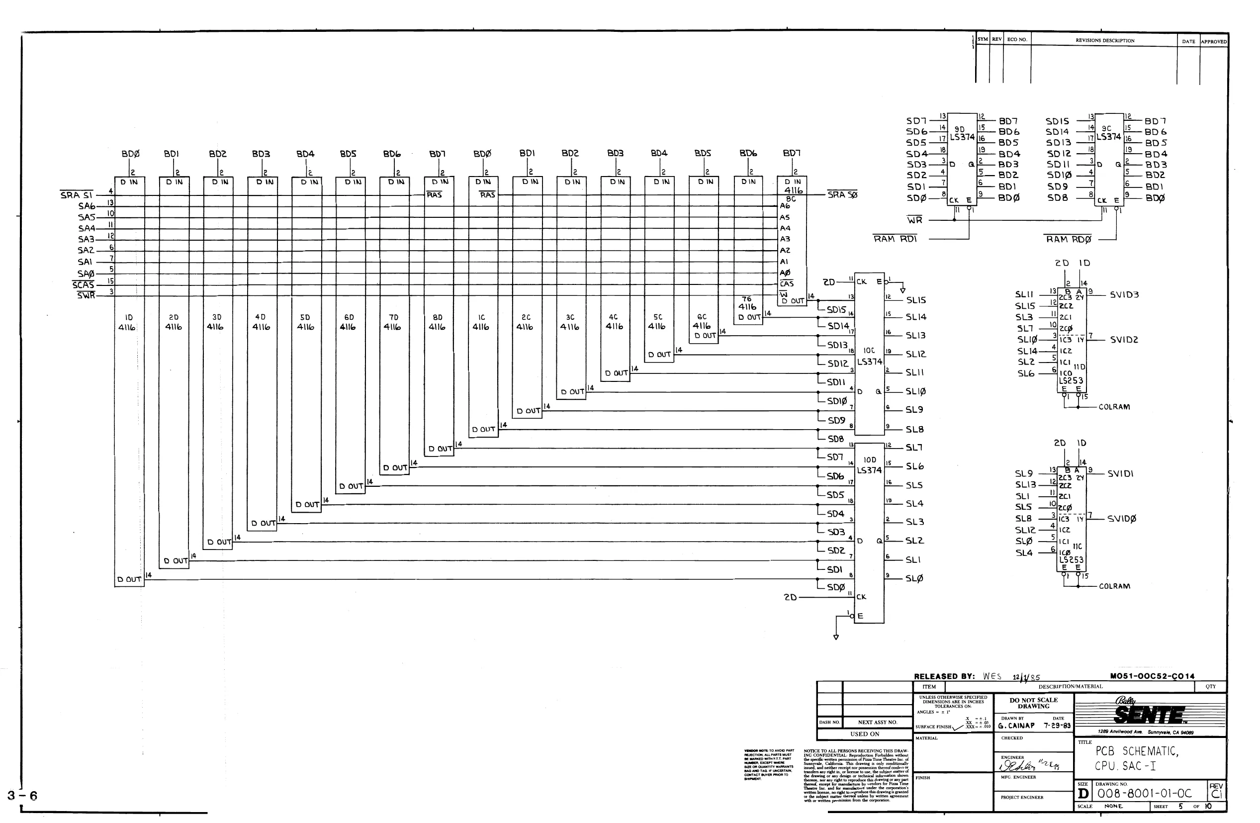
This page is a drawing, shown as the original scan.
ss $s § 8S LeoeE Lk Bo) 23 67 | |e 13 15 Iu H BLANK cik | BLANK
2 6 fle |19 Ss [9 fi4 fle [3 fr fie pa
«2 14D s S58 MBLANK S11 ¢ cE UL
| . | 00 | — | 13 14 15 | |
| pis" —4 | Ru | i | | |
PS ]
| iis |4 fs e Js | ifs le |s fe do | ip |4 |s je 49 |
wile A BC Dw), = {ciRA B CD UD cik AB CD OW tac
| cn $163 13D Re | 7 aad $163 «2D | ENP 15163, | ||
| ENPa gaa | ENTea gaa | ENTa ga a@ | ||
| | | cK A | cD | cK A BC | cK A BC OO |
| 2 [4 fis fie fr | fe fia fis fle fil | 2 f4 fle | ||
| im 24 6 | 16 iz a Ke | 16 32 Lt ie | ||
| vMM | M | MoM | ||
| | | HH HOH | WwoHOH OH | VvVVY | |
| SMHz. | + | 7 | —— |
- 13)
| | | MBLANK | vis —& | u | Api | a2 —pis* |
| + | 5 | al? | |||
| —__ | pess——4y | a| | oe | a | |
| HBLANK —~{ | 13] 136 | le | 12] a | 7 | * |
| ip | MBLANK | L | D3 Lae} —pess | ||
| | | MBLANK =" | m | $ | 10 | 13| 9 ale poset |
warann—t oe | aye — des
| 3 | 4 | 2 _ EOMPBLANK * | 5 a3}! mw BLaNk* |
| . | | cOMPBLANK —4 | 8 | a3U_— MBIANK * |
S — yeLANk* smaz eux oats | eG CLR RELEASED BY: Wes 12//ez MO51-00C52-C014 Ril ~ DESCRIPTIONMATERIAL
a ae TUNLess OTHERWISE SPECIFIED DIMENSIONS ARE IN'NCHES TOLERANCES ON
PCB SCHEMATIC, | Ee Soe peemen malas, tft Fis CPU, SAC -I
L ee oe = coe S37
H FLUP—e Sue
SLO
SLB
MPICCLK
sus
sL4
sua
sz
su
sip
MPICCLK:
4 Wee Te) LiIeG
|e, 40—+2 2d 13 Uiee oct2) 25> eo-+ =, 2 “Ts }s0d*-<as—o 20
- i280 a —o 13, D208 _Ti2}jse>+ oxa—os GAIS O's U2A iS GAS—OIB GAl4 O14 Be- a)seo>* U20a 2 seo eAx2—O21 GAI3 O1 L20A
Gale Os
6A ———Oll GAl0——Ore GAZ ——-O13 GAB —Ol GAT —O8 GAG ~O5
2sO GDT 230—— 606 2e7O— 605
230— Gb4 le be
24Q— G03 22O— Gde 2O— edt 28O— ooo ii MBLANK ls [s |e |. be | HBLANK
M BLANK
IBA
eMH SsIsST at [REVISIONS DESCRIPTION
PROPRIETARY INFORMATIO
MO51-00C52-C014 DESCKIPTIONMATERIAL Tauess OTHERWISE SFECIEEED
A pierre sk Be tie = uzies 1289 Anviiwcod Ave Sunmvnia CA S408 "PCB SCHEMATIC, CPU, SAC-I NOTIGh.T Lu pensonsnscering Ts Dna
——=—{B 008-8001-01-0C onthe et ma here unless wen peti fmt ogre
a leslew aor onsen
ima wmatankttg cK. MH
15,
MO5 1-00C52-C014
‘the wg nt he ihr wae person Pom AU FERSONS RECEIVING THIS DRAW Tupareasr’ Nous deka Nmenocerr mere $a ‘radon Prien wie DESCRIPTION/MATERIAL
TUNcess OTHERWISE SPECIFIED SSHWENSIONS ARE IN INCHES TOLERANCES ON DO NOT SCALE DRAWING.
a SS G.CAINAP 8-1-B3 7289 Anuiinood Ave Sunn
SCHEMATIC, CPU, SAC-I Te
ng APELIN * 853
REV 008-8001-OI-OC_ {Cl [scare NONE sd
REVISIONS DESCRIPTION
ALL RESISTORS 2.2K IN Ib PIN OIP EXCEPT WHERE NOTED
Jo jen fo fs [> eo Iw
sor—e| non—es wor—e—y aco 009. =08 -ow wow—s 3 RPS, VA
| 4 | 5 | RPS |
| A | 7 | RPS |
D ie
| a | : | i16 |
“ea “or “62 %3 Ys 5 Ys *07 So $1 087_ G9 usize 3 fe fia |s js i 6 8
| ia | | | mM | to _RPS |
808 BDI BO? BD3 BD4 BOS BDS BDT WWE
By g
t al 14] comp elaca cuxl® BLank® LS CUy
| T | 4 | 7 | RPG | RP4 |
+ * L 16 T it
| 1BG | 10 | 9 | a |
Lsire ae
| RPE | re | eN3904 | ||
| Mm | io | RPG | fr | |
| D | a | wy | + | +— |
6 1 RPB RPS
| tr | La | 13 | ye | RPG | iV | io | R32 |
| 6 if 18 | 0 | Q | ws | “T5 | Tie | aa | |
| % | RPE | SRPB | |||||
| 244 | j | 4 | 15 | RPG | n | 5 | RPE |
a aan ¥ +
| * 9 | WWE | ws |
I Smiz=— I cuk CONPBLANK™ cir
NOMIC. 10 ALL. PERSONS RECEIVING THIS ORAW to Ropedicton Pung
tia dnegh pened See lie ater hee ns by sen ton “OIMENSIONS ane IN TRCHES DO NOT SCALE “TokrmancEs oN DRAWING DESCRIFTIONIMATERIAL Rye MO51-00C52-c014
G.CAINAP 8+1-83 ee a MLE ae ENGINEER PROJECT ENGINEER SE] DRAWING NO. PCB SCHEMATIC, CPU, SAC-L
D}008-8001-01-0C Stale NONE
This page reads as a drawing: its text was drawn rather than typeset, and comes out in fragments. See the original scan.
This page reads as a drawing: its text was drawn rather than typeset, and comes out in fragments. See the original scan.
This page reads as a drawing: its text was drawn rather than typeset, and comes out in fragments. See the original scan.
This page reads as a drawing: its text was drawn rather than typeset, and comes out in fragments. See the original scan.
REVISIONS DESCRIPTION PROTOTYPE
PRODUCTION RELEASE RI-R4 WAS 2.2K 5 RI-R4 1S 3.3K] ./
© O.10/100V
cs cre -033/100V IN@14 4 +¢-
RB {OK
Ur, fo Ci
cRi INQI4 +
Row 10/3/2 MO5 1-00B18-A008
DESCRIPTION MATERIAL
ee oe DRAWING NOTES: UNLESS OTHERWISE SPECIFIED stm, Be ene on |. ALL CAPACITORS ARE IN MICROFARADS, 0.1/S0V. cmeeneo a ef
- ALL RESISTORS ARE IN OHMS, 74 W, 5% SEAT” Nresmauabtranearcenmneass one, L. Fears fe: PCB SCHEMATIC,
3. LAST REFERENCE DESIGNATOR USED: ae ses te TRACKBALL CONN, 3
RIO, cS, cRe, UB, s2. Sache pore — a Sone ere
FI
Fa 3A/250V
FS 3A/250V
F2 34/250V REV] ECO No. REVISIONS DESCRIPTION
A |\984] PRODUCTION RELEASE [8 1998 LEASED REDESIGNED PCB Tee RG
b23
tg +12V UNR <=——#— +15V +
co i
RELEASED BY: NOTES; UNLESS OTHERWISE SPECIFIED
|. ALL RESISTORS ARE IN OHMS , /aW,5%,
2, ALL CAPACITORS ARE IN MICROFARADS.
- LAST REFERENCE DESIGNATORS USED: R25, C27, D2S,UG ,Q2,F5.JI9,SCRI.
- HEAT SINK ATTACHED TO AUDIO GROUND.
- /f7 = audio GND Uv = GND
WES 2/36 M05 1-00C52-B8018 MR5O1 RT fie) : U3
| if | MC78I2 | =*1ey |
| cll | —3 | + cle |
6800 = 10
| 25V | V | 50v |
Dal Vv
MR5OI
| 2 | ve | 3 | - |
| mc79i2 [ | T | ealey |
clo 7 cia
6800 = =i0
| 47 25V | V | +) Sov |
2 V
MR5O! us 13 LMCc78I5 + T
| +] 4 | > | 024 | + |
5 6800 4 ursoi 25v ny 1, /77 177
+12V UNR
6800 25v
V DESCRIPTION MATERIAL DO NOT SCALE DRAWING
‘CHECKED L. Forre SCHEMATIC, LINEAR POWER SUPPLY
FROJECT ENGINEER 008-8009 -10-0B
IN
GNO | IN
| GND PWR J4
FG
Ra
POT VOLUME CONTROL|
[#———>-l2v
t>— ti2V UN BS (42K Rev Dy +I1SV REVISIONS DESCRIPTION
c22 ! 10 SOV c8 Sov 1000
TDAZOO2 SOV
4 + > ——*t
(a
rid 220 a
RI C2 R22 f ay? S28 470 220 I6V R23 2.2 +15V
cs 1000 SOV + “T ce R20 al C24 47 VvaWw SOV 022 =
r Re 5Y cig i Ey rf
16V ooo
RIS 2.2
‘77
MO51-00C52-B018
NEXT ASSY NO.
USED ON anus =f
woteonnort: ro Avo rART NOTICE TO ALL PERSONS RECEIVING THIS DRAW. ING COMFIGENTIAL Wapnicien Purlen won,
‘ree person om the coors DESCRIPTION/MATERIAL
1289 Anvlwood Ave _Sunmprale, CA 94089, E SCHEMATIC, LINEAR
POWER SUPPLY 3-15
SIZE] DRAWING NO. REV! D] 008-8009-10-08 TT
scace_ NONE. wee 2 OF
: B
BBs Bet 2—NV RECALL ‘S RON STIL + tea fe) q
=
~i2 i a in} Zz ait gasditaasads
SAS oe osteo V +5 ROM = 60g —+ a cE 22,
- GND
28h vcc Bow ao vpp Avpp uss | use | ves | uve | ves u9B 2764 | 2764 | 2764 | 2764 | 2764 | 2764
| ce | cE | cE | cE | cE | ¢E |
| 20 | ‘cm Yee ‘Yes | 0 | i | ||
| Ges | GRA | GS | GRR | LC (<( |
+5 ROM REV] ECONO, REVISIONS DESCRIPTION pare [approven| ¢ pres U2C, DELETED U3B ADDED U8B,U98, U8A ,U9A ,ULC,
457TL
: NIC
NIC
ROMABS:
‘ROMAB4
ROMABS
ROMAB2
ROMABL
ROMABG AS ROWEF
| pas 254— | AB | Baia | ROMCD |
| es? 2 | a7 | BALS |
Bae + AS
| aap | — | AS |
| BA4 | Ad | Vv |
sas Ag
| aa2 8 | se | a2 |
| Bar | —— | AL |
| Bag 40} | r | ag |
207 42} — 07 a6 18 06
| 805 7 | i} | +5 TTL |
8p4 D4
| ap3 48 | D3 | 18 | ||
| poz 43 | pe | STORE —2d store YS 7} 4 an7 | ||
| ep 42 | ot | BD3 | 04 | ast ane |
4h 14], VIB 16
| B09 | op | 802403 | as | — sas |
| __ | a | t3]__x2212 | [> | |
| oe 22 | OE | B01 —=|p2 | A4-S— Baa | |
| i | “Toxo | app—2244 or | a3}2— aaa |
eoneren 10, +5 ROM < vee mL -4%4 RECALL az}4— paz
| Pen 24) | Bev] | NOVI _7 gee | at [5 par |
ay id we 6
| vpp —£ | vep | BRIW —*4 WE op AD | Bad | |||||
| UlA | U3A | U4a | USA | U6A | UTA | U8A | USA | B |
2764 | 2764 | 2764 | 2764 | 2764 | 2764 | 2764 | 2764
| cE | ce | cE | ce | cE | cE | cE | ce | Avi |
| ics | Te | fe | ye | Ye | ie | je | ic |
ROMEF ROMCD ROMABS ROMAB4 ROMABS ROMABZ ROMABL ROMABO
45 7TL NOTES: UNLESS OTHERWISE SPECIFIED 1, ALL CAPACITORS ARE IN MICROFARADS ,.1/50V.
NEXT AS8Y NO. & SURFACE FINISH RO USED ON
ING CONFIDENTIAL: Reprodytion Fre wits pe ten perusal fen Tne nt ie a i ‘edema of any design oe esha ‘Rens any gto aNcLEs = =I"
fcrehecintta
iy vendors for Pass DO NOT SCALE DRAWING
L,PERCIVAL 5/234
Lo Fowte eS
[vr] ENGINEER PCB SCHEMATIC, CARTRIDGE , SAC-I
REVISIONS DESCRIPTION DATE {aPeroven|
+57TL
| | | Ag | eng2et— | E | Ws | u | = | 2 | |
| | | Al2 | pAle4 | +— | 12 | pce | ||
| oT A | BAIL | 1 | U2 2OMCDEEF | ||||
| —— | Vi | t | uI-e |
FOMCD4S:
| - | AO | Bape | 40 | ||||
| | | | | Tf | LRowcDZs | ||||
| —. | Ag | Base | 9 | PAL | |||
| | | OL | HS ROMCDOT | |||||
| as | eae 25 | 8 | a | ||||
| i | P| | 8 | ‘de | 3b ROMABE? | |||
| t | |A7 | BAZ | + | 7 | vic | i | a |
| | | i | ae | bae4 | las | LS ROVT | isis8 | ROMABAS |
| t | t | fi | |||||
| | | a | nas | | | les | Bye | BANK2g | ip OMABES |
| | | ~ | 8 | BANK 1-244 | o ROWABBT | |||
| Ad | Ba o-}——_- | ag | 9 | ||||
| cas 4 | t | a3 | BAB | T | a3 | ||
| oxe | - | + | a2 | B28 | a2 | exo | |
| eas 2 | + | L | lal | a 2 | 7 | Al | |
| cag 14 | | | t | af | Bag | 4p | 457TL | |
| oo7 9} jt | g0742 | 7 |
it 18
| 12 | i | i | _ | |||
| - | 6 | Ci | ||||
| eee | t | | | 6 | 806 | pe | STORE -% store VEC all Baz |
| 7 | i | | | ||||
| ous 42 | { | 5 | B05 | 25 | 803-5| 04 | Ae}? 846 |
| na 18 | 16 | _ | ||||
| 6b4 | t | 4 | Bp4 7 | i | e02403 vig a5\'S.8a5 | |
| oo 3h | i | | x2212 | ||||
| es 7 | T | 3 | 803 3 | 01 4 og | aat2gaa | |
| we | 2 | B02) | Bp 21 p; | A3-L 643 | ||
| 201 22h | 12! | ‘ | ||||
| 601 | jor | or | NVRECALL!S RECALL | «Aa 4 Ba | ||
| uw | _ | ——— 7 <- | ||||
| as 22 | pe | Novia cE | Al-egal | |||
| oF id | OE | = | — | BR/W-A WE yy ALS Bao |
GND iJ +5 20M—28 vee —
| Bem 2 | BGM | on oe | - | | | _ |
t
| VPP. | vp. | vpP | — | a | — | — |
| vse | vas | use | ues | via | uea | U3a | uaa | usa | U6A | Uza | bea |
z e7ize | e7i2e | 27126 | e728 27128 | 27128 | e728 | e7i2e | 27128 | 27iee | 27iee | 27128
| S34 | — | -_ | — | _ | |||||||
| Rare | FI | . | |||||||||
| oe | cE | ¢ | ¥ | € | ¢ | * | oe | SE | + | a | NOTES: uNLESS OTHERWISE SPECIFIED. |
| oa Bary | | | an | a | I | | | I. ALL CAPACITORS ARE IN MICROFARADS, I/50V. | |||||
| o-§2 5 TT, | GR67 GR45 GR23 GRor | ROMCDGEF ROMCD45 RoMcD23 ROMCDBI ROMAB67 ROMABYS ROMAB2S ROMABSI |
oe 5 Ser
‘ 2 ERE? 15159 240 oRas A082-91798-A000 ipLaRe3 RELEASED MO5 1-00C47-A018
| \2 oro | Tre] Orv | DESCRIPTION / MATERIAL | P/N REF |
ae i: —_———
| er | ND | . STRATMANN =} |
Te
| p | _ | orice ro ae reas necno pet ORG | = | PCB SCHEMATIC |
i Teen
| 4 | pr | lek CARTRIDGE, SACI |
MFG ENGINEER Size | DRAWING NO. REV A Tapecrananan D| 008-8025-0!__ fA 35 SCALE NONE ser 3-17
This page reads as a drawing: its text was drawn rather than typeset, and comes out in fragments. See the original scan.
B+ oO eer 0 Bp oO Brg 08 Mtewm.02=—NvRecr.
is ANY en
Ae
Asm
lof As,
jaz.
lat
led
ped.
t
263,68 668, choice cist og & a 272% vA ver i komme Bear! prom i
Ey
Teves, syed ge 8 ° vo
i tai = Fy
I = roo
ees ayy
> z ® lo e
RELEASED BY: J J 9221/96 _Mo51-00114-A149 ‘DESCRIPTION / MATERIAL ‘Denon nen CHES
ULTRA Chath bes 250K, SECURE
DRAWING NO 028 - 8030-
FIRMWARE :
—eef D-BUS ys (208)
8 |SEND
10 [REC
9 [SOOKHZ SERIAL L/O
‘DACL (2,88) DACM (2,88) SIBTR PIN9 (3,08) 1 SHAD PIN 9 (3,06) i ENAUD (2,86) i
—STUNE (2,88)
NOTES: UNLESS OTHERWISE SPECIFIED 1, ALL RESISTORS ARE IN OHMS, /4W, 5%.
- ALL CAPACITORS ARE IN MICROFARADS , .OI / OV. MO5I-00C52-BOI6
- LAST REFERENCE DESIGNATORS USED: R124 ,Ci48, 934, CR4, YI. DESCRIPTION MATERIAL
L.PERCIVAL_1/24/ LFoare_'/27/ea SCHEMATIC, AUDIO, 6VB
8-20 ; an eae 008-8002-10-0B
This page reads as a drawing: its text was drawn rather than typeset, and comes out in fragments. See the original scan.
This page reads as a drawing: its text was drawn rather than typeset, and comes out in fragments. See the original scan.