Asteroids DP-143-6th-01B
Asteroids (rev 4) (Atari, 1979) · Drawing Package · 1 pages · original scan
ADDRESS DECODING CIRCUITRY
| CLOCK CIRCUIT | es | MPU CIRCUITRY |
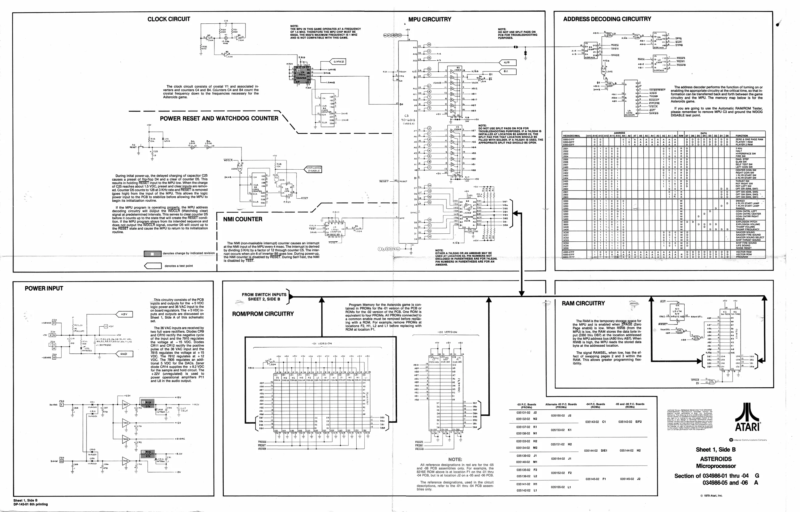
‘The clock circuit consists of crystal Y1 and associated inverters and counters C4 and 84, Counters C4 and 4 count the trystal frequency down to the frequencies necessary for the Asteroids game, ‘The address decoder performs the function of turing on or ‘enabling the appropriate circultry atthe citcal time, so that information can be transferred back and forth between the game circuitry and the MPU. The memory map below is for the Asteroids game.
It you are going to use the Automatic RAMIROM Tester, please remember to remove MPU C3 and ground the WOOG DISABLE test point.
Bibs ee’ POWER RESET AND WATCHDOG COUNTER \ eae 90-6013 Nove DO NOT se spurt pans ow ce FoR. 497 TROUBLESHOOTING PURPOSES. IFA 74.9244 15 INSTALLED AT LOCATION B2 ANDIOR C2, THE
ai Seirvesr ow tert com Sw ERTERCOM mal 5 During inital power-up, the delayed charging of capacitor C25 fiche Con gH
| ‘causes a preset of flipfiop D4 and a clear of counter D5. This | sl | cr | 2Fuinstan |
fesults in holding RESET input tothe MPU low. When the charge mse 90 ‘of 625 reaches about 1.5 VOC, preset and clear inputs are remov- ‘ed. Counter DS counts to 128 at 3 KH2 rate and RESET is removed {goes high) from the input of the MPU. This allows the logic Power Input to the PCB to stabilize before allowing the MPU to z
| begin its initialization routine. | { | on | oe |
U1 the MPU program is operating property, the MPU adcress = -
| decoding circuitry wil | biput the WOGLR (Watchdog clea) | — | ~ |
Signal at predetermined itera This serves to clear counter DS
| ton If the MPU programy | ste | ‘ | a | NMI COUNTER |
fam says from ts intended sequence and toes not output ine WCE signa counter OS wil count upto the RESET state and cause the MPU to return to its initialization routine, | Cain ENTRC TET
‘Rowvoue
Sticen souno sete
NORE RESET at tne nil inpat ofthe MPU every 4 mace. Te nferupt a deed coupe
| By ating 9K by | actor of 2 trough counter Ce. The ner | Ce@on0- | nore |
lezelezeeleces|eces|eeee|>na|>>22|>2>2]2>2>]2=22| | “The NMI (non-maskable interrupt) counter causes an interrupt Ih=a]pacloaocfooosfooosfpooe]oecfoooclacca[sooaloocs|
| ed | CC ee | ed | i | Erte a | su on an sos nay ae | 7 | = |
| the NMI counter ig disabled by: | ‘During Selt-Teet, the NM | nd | RED AT | LOCATION E8. IN NUMBERS NOT | B | broarale |
is disabled by TEST. PIN NUMBERS IN PARENTHESIS ARE FOR AN TTT essen am
POWER INPUT FROM SWITCH INPUTS. SHEET 2, SIDE B ‘This circuitry consists of the PCB, Inputs and outputs for the +5 VOC logic power and 36 VAC input to the ‘on board regulators. The +5 VDC in. puts and outputs are discussed on Sheet 1, Side A of this schematic ‘set RAM CIRCUITRY Program Memory for the Asteroids game is contained in PROMS for the -O1 version of the PCB or FIOM for the -02 version of the PCB. One ROM is. ‘equivalent to four PROMS. All PROMs connected to ‘a common enable must be removed before replacing with a ROM. For example, remove PROMS at locations F2, Ht, L2 and LT before replacing with ROM at location Ft. ROMI/PROM CIRCUITRY
‘The RAM Is the temporary stor the MPU and is enabled when. Gero Page enable) Is low. When RAB (from the MPU) is low, the RAM stores the data byte input (DB0 thru DB) at the location addressed by the MPU address bus (ABO thru AB). When IWS Is high, the MPU reads the stored data byte at tne addressed location. for Te 6 VAC inputs reseed by oe ei eee oe Te cheater ie
oe eae tye sos Ks, sale ot te 9 VAC ant St : 7815 regulates the voltage at +15 -o2 version
‘The signal RAMSEL, when low, has the ef-
| a | (OG. Tho Tete regulates at 12 | ata | toot f Seepning pages 2 one's win | ||||
| VOC. The 7806 regulates an addi | (Pave | Pane | Phat | RAM. This allows greater programming flex: | |||
| tional 5 VOC for the DACs. Zener | t | I | + | avo | nf? nee | Joss | iit. |
| dloae Gate suppl te | 2 VOC | avo | i | | | : | FS | |
| forthe sample aa hla teu. The | LLL | LE | EE LLL | bh. | 4 | 4 | |
| eaV unvulated is used to | Satyr | pears | a | = | i | ||
| cower. Sporetonaampiiers PIT | AAAS | Aiea | i | Mo | |||
| “ | Tes | 409 PC. Boards | ‘Alternate .03 P.C. Boards | 04. Boards | 06 and 06 P.C. Boards |
: q tt an fon es I: estat 2 costtooe 2 costse0e Ne
| - | oss14s02 ct | ossias02 | EF |
| | | o3s1s7.02 | Kt |
Pad rem oasisooz Kt
| tf mel | rey | oasi9e02 | NI |
| roe a | ¥ | 0513302 | He |
a oasisi02 Ha
| oes | peel | casiaec2 | DIES | casseao2 He | Sheet 1, Side B |
asis002 Jt casistaz 41
| NOTE: | oastao02 mt | ASTEROIDS |
All reference designations in red are for the -05 Microprocessor and .06 PGB assemblies only. For example, the ma
| 83162 ROM above lsat location Fi\on the Of thry | ossts202 | 2 | 034986-01 | thru-04 | G |
“06 PGB, but sat location J2 ona 05 and-06 PCB.
| — | meen | cane | Section o | oe |
‘The reference designations, used in the circult 034986-05
| descriptions, refer to the -01 thru -04 PCB assem- | ereroon et | 035155.02 Lt | ani |
biies ony. cos14202 U1
(© 1979 Ata, ne. Sheet 1, Side B DP-143.01 6th printing