Asteroids DP-143-4th-01A
Asteroids (rev 4) (Atari, 1979) · Drawing Package · 1 pages · original scan
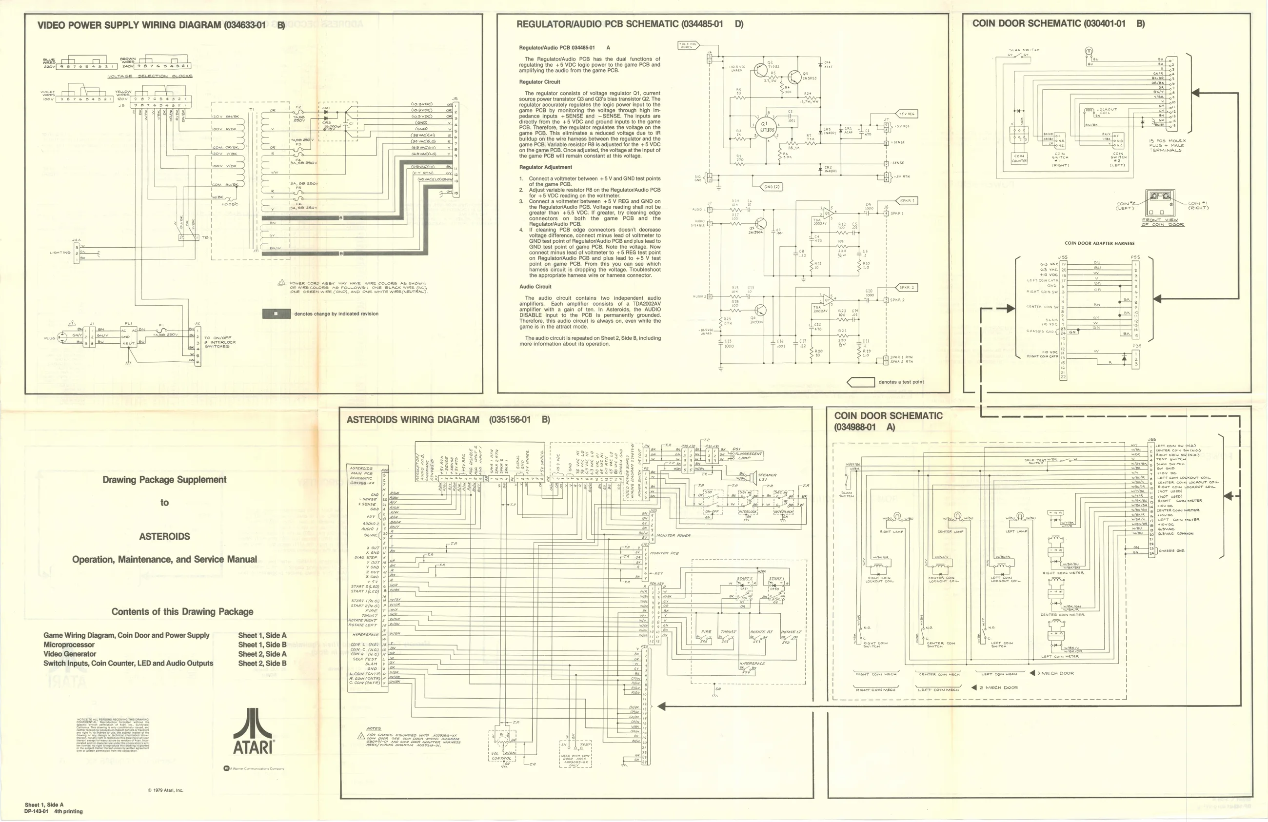
VIDEO POWER SUPPLY WIRING DIAGRAM (034633-01 B) REGULATORIAUDIO PCB SCHEMATIC (034485-01 COIN DOOR SCHEMATIC (030401-01 B)
RegulatorfAudio PCB 09448501 A ‘The Regulator/Audio PCB has the dual functions of regulating the +5 VDC logic power to the game PCB and amplifying the audio from the game PCB. Regulator Circuit we och oo] see ch “o[aereses ar) mofse7csesal]
‘The regulator consists of voltage regulator Q1, current 7 source power transistor Q3 and 03's bias transistor Q2. The aa Sosvoe regulator accurately regulates the logic power input to the coav {game PCB by monitoring the voltage through high imos vee) edance inputs +SENSE and ~SENSE. The inputs are ert direct trom te, +5 VOC and ground inoue to the game
———— the regulator regulates the voltage on the
game PGS, Tne olimates a reduced voltage sue 10 TR e eae Dulldup on the wire harness between the regulator and the 5 eae {game PCB. Variable resistor RB is adjusted for the +5 VDC " peters ‘on the game PCB. Once adjusted, the voltage at he input of i an = TeaiNaCS: the game PCB will remain constant at this voltage. Regulator Adjustment |. Connect a voltmeter betwoen +5 V and GND test points: of the game PC just varabe resistor 8 on the ReguatorAudlo PCB for +5 VOC reading on t Gonnect a velnetr between +2 V REG and GND on ry “ os Icom 2 the Regulatov/Audio PCB. Voltage reading shall not be cat é 4 é eign) ‘greater than +5: VDC. If greater, try cleaning edge ri connectors on both the game PCB and the
GND test point of ReguatovAuclo PCB and lus lead to H ai eee eae ens ae cates i ceecon nsrcomets connect minus lead of voltmeter to +§ FE test point ‘on RegulatorAudio PCB and plus lead to +5 V test point on game PCB. From this you can see which harness cifeult is dropping the voltage. Troubleshoot the appropriate hares wire or hamess connector. & coach ce ta SneeeeeN Auto Creu SIRSSE es ee ne Te nud, slout consis two Independent auto eto cach ans coi tee nzEA emptor wih aio terse nsacade te AUDNS [EIEN ois change oy nated roviion Seats een ate, eA Tel Wis uals sek ne ear eee ioms Nein ia nani ose ‘The audio circutis repeated on Sheet 2, Side B, including ‘more information about its operation.
ASTEROIDS WIRING DIAGRAM
Drawing Package Supplement RE irons 9 to
ASTEROIDS g RE
Operation, Maintenance, and Service Manual ¥ oxo
staar eno) Sraar /teo) sranr 1(x0)) Contents of this Drawing Package
Game Wiring Diagram, Coin Door and Power Supply ‘Sheet 1, Side A bait sige Microprocessor Sheet 1, Side B com & (wa) Video Generator ‘Sheet 2, Side A ‘Switch Inputs, Coin Counter, LED and Audio Outputs ‘Sheet 2, Side B
ae PECRER ERE OS REPS ESE RET COL ers
Ra a ET SER Tan a Tar egsme— qs mech voor SyP RSET Soe fewre) \wewrconmec’ = “Caer commen | 2 meen Door
(© 1070 Ata, ne
Sheet 1, Side A DP-149-01 4th printing