Missile Command Caberat DP-158-1st-01A
Missile Command (rev 3, A035467-02/04 PCBs) (Atari, 1980) · Drawing Package · 1 pages · original scan
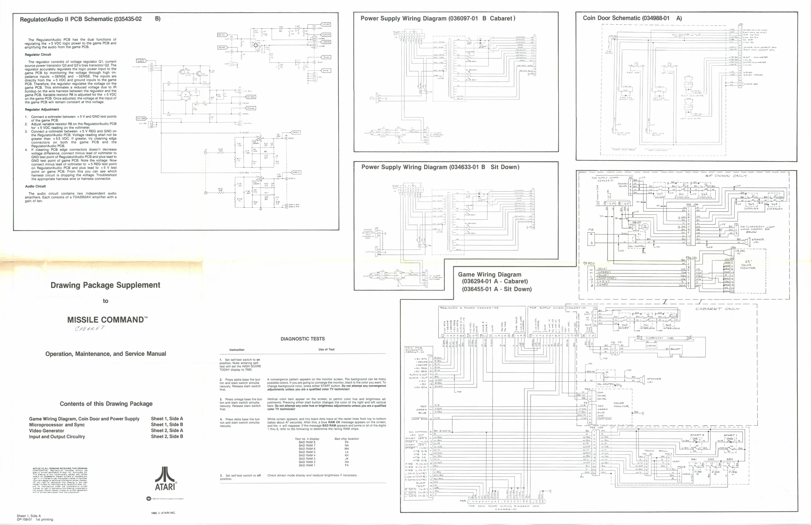
Regulator/Audio Il PCB Schematic (035435-02 B)
The Regulator/Audio PCB has the dual functions of regulating the +5 VDC logic power to the game PCB and amplifying the audio from the game PCB.
Regulator Circuit
‘The regulator consists of voltage regulator 1, current
source power transistor QS and Q3's bias transistor Q2. The
regulator accurately regulates the logic power input to the game PCB by monitoring the voltage through high im edance inputs +SENSE and ~SENSE. The inputs are id ground inputs to the game PCB. Therefore, the regulator regulates the voltage on the game PCB. This eliminates a reduced voltage due to IR.
Buildup on the wire harness between the regulator and the
game PCB. Variable resistor Fis aduste forthe +8 VOC
fn the game PCB. Once adjusted, the voltage at the input of,
the game PCB wil remain Constant at this voltage
Regulator Adjustment
1. Connect a voltmeter between +5 V and GND test points
Of the game PCB. 2 ‘Adjust variable resistor RB onthe RegulatoriAucio PCB "REG and GND on the Regulator/Audio PCB. Voltage reading shall not be ‘greater than +55 VOC. If greater, try cleaning edge connectors on both the game PCB and the Regulator/Audio PCB.
- If cleaning PCB edge connectors doesn't decrease voltage difference, connect minus lead of voltmeter to GND test point of Regulator/Audio PCB and plus lead to GND test point of game PCB, Note the voltage. Now connect minus lead of voltmeter to +5 REG test point fon Regulator/Audio PCB and plus lead to +5 V test ppoint on game PCB. From this you can see which
Power Supply Wiring Diagram (036097-01 B Cabaret)
Coin Dove Schematic Lecce A)
hhamess circuit is dropping the voltage. Troubleshoot the appropriate harness wire or hares connector.
‘Audio Cireult
‘The audio circuit contains two independent audio amplifiers. Each consists of a TDAZ002AV amplifier with a ‘gain of ten
Drawing Package Supplement
to
MISSILE COMMAND” C184 ET
Operation, Maintenance, and Service Manual
Contents of this Drawing Package
Game Wiring Diagram, Coin Door and Power Supply Sheet 1, Side A Microprocessor and Sync Sheet 1, Side B Video Generator Sheet 2, Side A Input and Output Circuitry Sheet 2, Side B
ATARI
19680 © ATARIING ‘Sheet 1, Side A ad
P1581» 1st printing Instruction SIT DOWN ONLY
Ler 7
DIAGNOSTIC TESTS
Use of Test
4._ Set solttest switch to on position. Note entering sel {est wil set the HIGH SCORE TODAY display to 7500,
2 Press alpha base tre but- {on and slam switen simulta ously. Release slam switen fire.
base tre but-
- Pross omega {on and slam swith simulta. ‘oousl. Release slam switch firs.
- Press delta base fire but ton and slam switch simulta ‘neously.
5,_ Set solttest switch to off position A someraence pata appears on the moni screen. The background canbe many ergo the monitor, black isthe color you want. TO
\wnite sereen appears, and tiny black dots trace al the raster lines from top to bottom (takes about 47 seconds). After this, a blue RAM OK message appears BAD RAM: fand the + wl eappeaIt the message ‘and some oral ofthe digits 4th 8 eter to te following to determine the falling RAM chips. Test no. 4 display ‘Bad chip location BAD RAM 8 Pe BAD RAM 7 Ne BAD RAM 6 ma BAD RAM 5 us BAD RAM 4 Ke BAD RAM 3 o BAD RAM 2 i BAD RAM + Fa
(Check attract mode display and readjust brightness if necessary. Game Wiring Diagram (036294-01 A - Cabaret) 4
(036455-01 A - Sit Down) [ ae nne ee een
CABARET ONLY
qi dd ——— ja [sewer] Breas