Rampart TM-366 1st Printing
Rampart (Trackball) (Atari Games, 1990) · Technical Manual · 52 pages · 70 sections · original scan
TM-366 1st printing
Operator’s Manual with Schematics
This page carries no recoverable text. It is a drawing or a photograph. See the original scan.
Warranty
Seller warrants that its printed-circuit boards and parts thereon are free from defects in material and workmanship under normal use and service for a period of ninety (90) days from date of shipment. Seller warrants that its video displays and laser video disc players (in games supplied with displays and video-disc players) are free from defects in material and workmanship under normal use and service for a period of thirty (30) days from date of shipment. None of the Seller’s other products or parts thereof are warranted. If the products described in this manual fail to conform to this warranty, Seller's sole liability shall be, at its option, to repair, replace, or credit Buyer’s account for such products which are returned to Seller during said warranty period, provided:
- Seller is promptly notified in writing upon discovery by Buyer that said products are defective;
- Such products are returned prepaid to Seller’s plant; and (©) Seller’s examination of said products discloses to Seller's satisfaction that such alleged defects existed and were not caused by accident, misuse, neglect, alteration, improper repair, installation, or improper testing. In no event shall Seller be liable for loss of profits, loss of use, incidental or consequential damages. Except for any express warranty set forth in a written contract between Seller and Buyer which contract supersedes the terms herein, this warranty is expressed in lieu of all other warranties expressed or implied, including the implied warranties of merchantability and fitness for a particular purpose, and of all other obligations or liabilities on the Seller’s part, and it neither assumes nor authorizes any other person to assume for the Seller any other liabilities in connection witb the sale of products by Seller.
The use of any non-Atari parts may void your warranty, according to the terms of the warranty. The use of any non-Atari parts may also adversely affect the safety of your game and cause injury to you and others. Be very cautious in using non-Atari-supplied components with our games, in order to ensure your safety. Atari distributors are independent, being privately owned and operated. In their judgment they may sell parts or accessories other than Atari parts or accessories. Atari Games Corporation cannot be responsible for the quality, suitability or safety of any non-Atari part or any modification including labor which is performed by such distributor.
Dedicated three-player game TM
Copyright © 1990 by Atari Games Corporation. All rights reserved. No part of this publication may be reproduced by any mechanical, photographic or electronic process, or in the form of a phonographic recording, nor may it be stored in a retrieval system, transmitted, or otherwise copied for public or private use, without permission from the publisher. The game play, all graphic designs, this technical manual, its accompanying schematic diagrams, and the display manual are protected by the U.S. Copyright Act of 1976. This Act provides for substantial penalties for violating federal copyright laws. Courts can Rampart 3-Player Game
NOTICE
NON-
PARTS
impound infringing articles while legal action is pending. If infringers are convicted, courts can order destruction of the infringing articles. In addition, the Act provides for payment of statutory damages of up to $50,000 per infringing transaction in certain cases. Infringers may also have to pay costs and attorneys’ fees and face an imprisonment of up to five years as well as fines of up to $250,000 in the case of individuals and up to $500,000 in the case of corporations. Atari Games Corporation will aggressively enforce its copyrights against infringers. We will use all legal means to immediately halt any manufacture, distribution, or operation of a copy of video games made by us. Anyone who purchases such copies risks forfeiting such a game. Published by: Atari Games Corporation 675 Sycamore Drive P.O. Box 361110 Milpitas, California 95036 Printed in the U.S.A. 12/90 Produced by: The Atari Games Technical Publications Department. Writing and Editing: Andrea Dencker Illustration and Design: Mary Ohanessian Sumner You may void the game warranty (printed on the inside back cover of this manual) if you do any of the following: ¢ Substitute non-Atari parts in the game.
- Modify or alter any circuits in the game by using kits or parts not supplied by Atari Games Corporation.
- On games provided with an Electromagnetic Interference (EMI) ground cage, be sure that the game printed-circuit boards (PCBs) are properly installed on the EMI ground cage and that the end board is securely installed with all screws in place and tightened. If you are still unable to solve the interference problem, please contact Customer Service at Atari Games Corporation. See the inside front cover of this manual for service in your area.
Rampart 3-Player Game
SUMMARY
The following safety precautions apply to all game operators and service personnel. Specific warnings and cautions will be found in this manual whenever they apply.
ABOUT NOTES, CAUTIONS, AND
WARNINGS In Atari publications, notes, cautions and warnings have the following meaning:
iii
Rampart 3-Player Game
3 Maintenance and Troubleshooting 1 Set-Up Repairing the Video Display . Repairing and Replacing the Midi Tra! How to Use This Manual 11 ROMs and RAMs Inspecting the Game... . 12 4 Parts Illustrations Control and Switch Locations
13 ‘See the List of Illustrations that follows. Installing the Control Panel... Setting the Coin and Game Options. Maximizing Earnings Game Play... 1-3 i . . ns 1 “5 Schematic Diagrams 2 Self- Test . See the List of Illustrations that follows. Introduction ,, Entering.and Exiting the Select Test Ment Statistics .....
Controls Test Complete RAM Test Complete ROM Test Playfield Test. Motion. Object Color Test... Color Purity Tesi Convergence Te:
Rampart 3-Player Game
IL
Figure 1-1
Figure 2-1 Figure 2-2 Figure 2-3 Figure 2-4 Figure 2-5 Figure 2-6 Figure 2-7 Figure 2-8 Figure 2-9 Figure 2-10 Figure 2-11" Figure 2-12 Figure 3-1 LUSTRATIONS Figure 4-1 Figure 4-2 Control and Switch Locations... Figure 43 Figure 4-4 Self-Test Menu Screen Statistics Screen. Figure 4-5 Game Options Screen Figure 4-6 Coin Options Screen . Sound Test Screen . Controls Test Scree: Figure 5-1 RAM Test Menu... Complete ROM Test Screen Figure 5-2 Playfield Test Screen. Motion Object Test Screet Color Test Screen... Convergence Test Screen Figure 5-3 Figure 5-4
_. Figure 5-5
Table 1-1
"able 2-1 Table 2-2 Table 2-3 Table 2-4 te Table 2-5
“Table 3-1 Table 3-2
Table 3-3 Maintaining the Midi Trak-Ball ....
Cabinet-Mounted Assemblies. Control Panel Assembly ... Midi Trak-Ball Assembly .. Coin Controls, Inc. Coin Door Assembly ... Power Supply Assembh Rampart Game PCB Assembly @-Player Version)
Rampart Game PCB Assembly Schematic Diagram... JSA Audio 11 PCB Assembly Schematic Diagram. Game Wiring Diagra: Rampart Coupler PCB Assembly Schematic Diagram... Faulty RAM/ROM Tables . 5-2
Game Specifications ...
Summary of All Self-Test Screens Game Option Settings Coin Option Settings .. Bad RAM Locations by Error Addres: Bad ROM Locations by Error Address . 2-2
F Troubleshooting Table. Voltage Inputs and Test Points on the PCB .. ie What ROM Problems Look Like.
Rampart 3-Player Game
WIP Pye]
vi
Prrrrrrrrere CHAPTER 1
Set-Up
How to Use This Manual
This manual is
written for oper-
ators and service
personnel. It provides information for set-
ting up, playing, testing, and maintaining your Rampart™ three-player game. The manual is divided into the following chapters: Chapter 1 contains set-up and game playing information. “ Chapter 2 describes the self-test and how to use the self-test screens. “ Chapter 3 contains main-
tenance, repair, and _trouble-
shooting procedures. Be sure to
perform the preventive mainte-
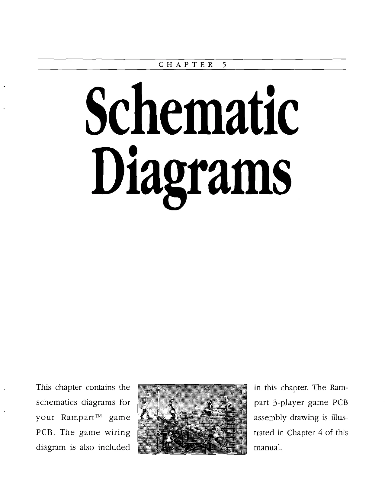
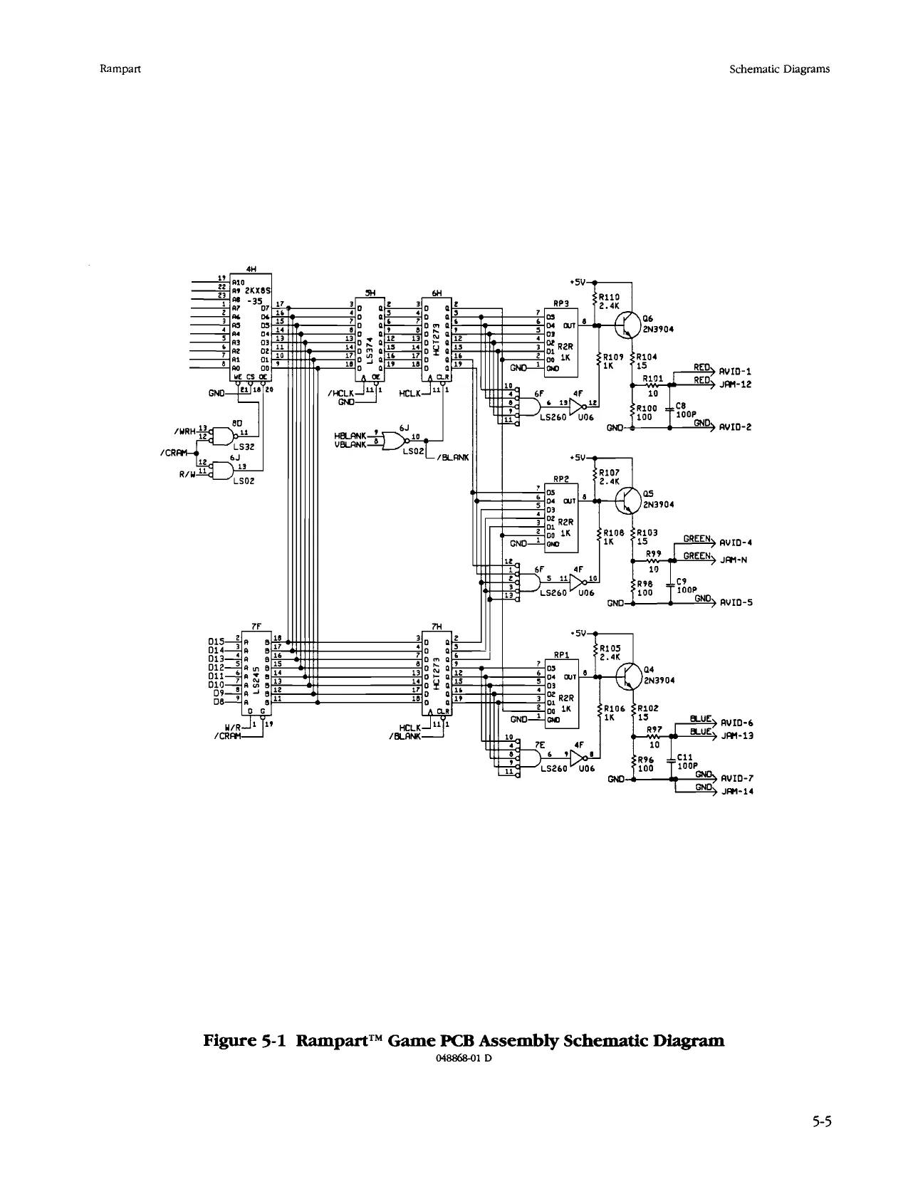
nance tasks to keep the game in good condition. Chapter 4 contains the parts illustrations. Chapter 5 contains the schematics for the Rampart game printed-circuit board (PCB) and the Midi Trak-Ball coupler PCB, plus the game wiring diagram.
Set-Up
Inspecting the Game
This cabinet should be connected to a grounded threewire outet only. If you have only two-wire outlets, we recommend that you hire a licensed electrician to install grounded outlets. Players can receive an electrical shock if the cabinet is not properly grounded. Inspect your Rampart game carefully to ensure that the game is complete and was delivered to you in good condition. Inspect the cabinet as follows:
- Examine the exterior of the cabinet for dents, chips, or broken parts.
- Open the service door. Unlock and open the coin doors. Inspect the interior of the cabinet as follows: a. Check that all plug-in connectors on the cabinet harnesses are firmly plugged in. Do not force connectors together. The connectors are keyed so they fit only in the proper orientation. A reversed connector can damage a printed-circuit board (PCB). This will void your warranty. b. Ensure that all plug-in integrated circuits on each PCB are firmly plugged into their sockets. c. Inspect the power cord for any cuts or dents in the insulation. d. Inspect the power supply. Make sure that the correct fuses are installed. Check that the harness is plugged in correctly and that the fuse block cover is mounted in place. Check that the green ground wire are connected.
Table 1-1 Game Specifications Characteristic Specification - Power Consumption 127 (), Wimaximum Line Fuse Rating 3 Amps Line Voltage 102'to 132 VAC. Temperature 5° to 38° C (37° to 100° F) Humidity Not to exceed 95% relative Width 33.25 inches (84 crn) Depth 38.25 inches (97 cm) Height 71.75. inches (182 cm) Weight 325'Ibs 148k) ; Rampart 3-Player Game
e. Inspect other sub-assemblies, such as the video display, controls, printed-circuit boards (PCBs), and speakers. Make sure that they are mounted securely and that the ground wires are connected.
Control and Switch Locations
Most of the controls are located inside the drawer, behind the control panel (see Figure 1-1). The only exception is the power on/off switch. Power On/Off Switch The power on/off switch is located at the top left of the cabinet (behind the peak). Volume Control The volume control is located on the Rampart game PCB, which is in the drawer behind the control panel. Self-Test Switch The self-test switch is also located on the game PCB, in the drawer behind the control panel. Coin Counter The coin counter is located on the bottom of the coin box, inside the lower coin door.
Installing the Control Panel
Make sure the game power is turned off. To install the separately packaged control panel, you need the following tools: ° Hex driver or wrench
- Four flat washers (provided with game)
- Four nut-washer assemblies (provided with game)
- Reach in through the openings on the front of the drawer, and open the spring draw latch on each side. Pull the drawer out partly. (See Figure 1-1.)
- Hold the control panel up to the front of the drawer, and match up the four threaded studs with the four small holes (one in each corner). See Figure 1-2.
- Install one flat washer and nut/washer assembly onto each threaded stud.
- Plug the two control panel harness connectors into the game hamess inside the drawer. These connectors are interchangeable, so be sure to match wire colors. Plug the ground wires together at the Faston connectors. This step is very important, since this wire grounds the control panel.
- Close the drawer and snap shut both latches.
Rampart 3-Player Game Set-Up
i) Volume Controt Sait-Test Switch
Figure 1-1 Location of Volume Control and Self-Test Switch
- Turn on the game power. Check that the video display and the attraction lamp have power.
- Observe the screen: you should see the attract mode displayed. If the screen remains a solid white, red, or blue color, you have a RAM failure. These failures are as follows:
White Color RAM
Red Bit-map RAM Blue Motion-object RAM
Setting the Coin and Game Options
The Rampart coin and game options are set in the selftest. Refer to Chapter 2 for the recommended settings and the procedure for setting the options.
Game Play
This section of the manual describes the theme of the Rampart game and the game play features. Introduction Rampart combines the best of strategy puzzle games with dynamite action and the excitement of head-tohead competition. Up to three players can play at once to see who becomes the medieval overlord.
Play Mode
In the first phase of game play, players select a site for their home castle and position their cannons. Then, it’s on with the battle, as each side hurls projectiles to destroy enemy walls. Once the onslaught ends, the players must quickly rebuild and extend their walls before the next battle. The players must completely surround at least one castle in order to continue play. In a multiple-player game, the contest is head-to-head for an operator-selectable maximum of number battles (the factory setting is for seven battles per game). As long as a player can place pieces to surround at least one castle, he continues. If a player is eliminated, he may deposit another coin to continue. In a one-player game, the computer directs an invading armada against the player's castles. The objective is to establish a fort and expand your realm to the entire island. You must destroy the computer's fleet before they reach shore and move their cannons onto the land. In higher levels of game play, the computer cannon fire will leave behind burning rubble, preventing the player from repairing and extending his walls. Rampart’s action is lightning fast. The strategy is exhilarating. The thrill of head-to-head competition is intense.
1-3
Set-Up Rampart 3-Player Game
1-4
CHAPTER 2
Use the Rampart self-test to check the condition of
the game circuitry and controls. You will see the
self-test information on
the video display and hear the sound test infor-
mation through the speakers. You do not need any additional equipment to perform the self-test. “ You should perform the self-test when you first set up the
Self-Test
INTRODUCTION
purposes. game, each time you col-
lect the money, or when
you suspect game failure.
“ This chapter shows the screens in the self-test and
explains each of the tests. The screens and explanations are arranged in the order they appear in the self-test. Table 2-1 lists all of the self-test screens and their
Self-Test
Entering and Exiting
the Self-Test
To enter the self-test, turn on the self-test switch on the game PCB. Exit the self-test by switching off the self-test switch.
Select Test Menu
Choose which test or screen you want to see from this menu, shown in Figure 2-1. Move up and down the list by rolling the Trak-Ball; the corresponding test is highlighted in white. Choose the screen by pressing the red PLACE button.
Statistics
Use the information shown on the statistics screen, in Figure 2-2, and on the histogram screens to keep track of your game use and maximize your profits. Record the information on the Rampart statistics page in the back of this manual. The statistics are collected from the last time the statistics were cleared. You can clear the statistics by holding down the red ROTATE button and pressing the red PLACE button at the same time. Rampart 3-Player Game
THEN PRESS RED PLACE BUTTON STATISTICS GAME OPTIONS COIN OPTIONS SOUND.TEST CONTROLS TEST COMPLETE RAM TEST COMPLETE ROM TEST PLAYFIELD TEST MOTION OBJECT TEST. COLOR TEST. PURITY TEST CONVERGENCE TEST.
Figure 2-1 Self-Test Menu Screen
Press the red PLACE button to leave this screen and go to the histograms. « Left Coins show the number of coins counted in the left coin mechanism. Right Coins show the number of coins counted in the right coin mechanism.
Table 2-1 Summary of All Self-Test Screens
‘ROM Test Screen Playfield Test Screen Motion Object Screen” ‘Color Test Screen
Purity Test Screen Red Color Purity Screen, Green Color Purity Screen Blue Color Purity Screen ‘White Color Purity Screen
Grey Color, Purity Screen
White Convergence Screen
Violet Convergence Screen Green Convergence Screen Use or Purpose » ss Displays the game statistics. a
Use tO set and check the game options settings. ‘Use to set and check the coin optio1 "Sound Test Screen ‘Use to check the audio circuits. Controls Test Screen ‘Use to test the player control RAM Test Screen oe i ‘Video RAM ooping) Use to check the video RAM. “Color RAM (looping) 22, po Use’ to check the color RAM. All RAM (looping) eee Use to check all RAM: Fe TA > Use to check Mee program ROMS, cn Use to check the alphanumeri¢ « displays. Use to test the movement and color of game objects. ‘Usé 'to’check the video display color circuits.
~ Use to check the red color purity in he video display. Use to check the blue color purity in the video display. — ‘Use to check the white color in the video display, : Use to. » check the grey color in the video display: 2 Pp! ' Use'to check and pie video display convergent Use to’check and adjust video display convergence settings.
Rampart 3-Player Game
Statistics Left Coins : Right Coins 1838 Aux Coins 20
| Idle Mins | > | 26085 |
| 1 Player Mins | > | 8677 |
2 Player Mins 2272 3 Player Mins 1009 New Game Mins 9433 Cont Game Mins 3872
Left Pir Mins. 4219
Cntr Pir Minis 5964 Right Pir Mins © >). 3112 Active Mins 9487 Total Games 2624 Total Sessians 730
| 1PiBeginners. | : | 371 |
1 Pl Advanced 150 Error Count 9 Tolat Coins aa7t Avg Time/Coin 236 secs Pereéntage Play 26
HOLD RED ROTATE AND PRESS REO PLACE TO CLEAR STATISTICS.
PRESS REO PLACE BUTTON FOR NEXT SCREEN
Figure 2-2 Statistics Screen
- Aux Coins shows the number of coins counted on the auxiliary coin input. « Idle Mins shows the number of minutes the game was not being played. ° 1 Player/2 Player/3 Player Mins is the number of minutes the game was played by one, two, or three players. ° New Game Mins is the amount of time the game is played before continuation.
- Cont Game Mins is the amount of time the game is played during “add-a-coin” (continuation). © Left/Cnir/Right Pir Mins is the number of minutes the game was played at the left, center, and right player stations,
- Active Mins is the number of minutes the game was being played in any mode.
- Total Games is the number of games played (one game per player).
- Total Sessions is the number of sessions played. For example, one 3-player game counts as one session. © 1-PI Beginners is the number of 1-player beginner games played. ¢ 1-Pl Advanced is the number of 1-player “veteran” games played.
- Error Count shows the number of errors counted in the erasable memory. If you have an error count, the statistics may be wrong. If you consistently Self-Test
have errors counted for several weeks, replace the EEROM at 38F.
- Avg Time/Coin is the average number of seconds played per coin. + Perceniage Piay is the amount of time, as a percentage, that the game is played while it is powered on.
Game Options
Check and select the coin options on this screen, shown in Figure 2-3. To move through the options, roll the Trak-Ball up or down. Change the option in yellow type. The factory
GAME OPTIONS, RESTOHE FACTORY OPTIONS? NO CLEAR HIGH SCORES ON GAME DIFFICULTY: MEDIUM LENGTH OF 2 OR 3 PLAYER GAME:
ADDITIONAL ROUNDS AFTER ADD-A-COIN 4 BATTLES AUTO-RESET HIGH SCORES ON
PRESSING RED ROTATE RESTORES ORIGINAL SETTING PRESS RED PLACE BUTTON TO SAVE THIS SETTING AND EXIT.
Figure 2-3 Game Options Screen
default settings are shown in green. To change a setting, roll the Trak-Ball right or left. To save the new settings, press the red PLACE button. This returns you to the select test screen. If you want to keep the original setting, although you have changed it, press the ted ROTATE button. This brings back the original setting. Use the red PLACE button to exit. The game option settings with factory defaults are shown in Table 2-2.
Self-Test Rampart 3-Player Game
Table 2-2 Game Option Settings
Oonv Option ink Settings Explanation |; Pores
| Restore Factory Options | ‘Yes | Now | Lets ‘you ‘set all: the game options to, the facto. 9 option |
3 lets you use your own settings. ‘Make sure you set this to’
| . | . | ‘no to ‘use-your own chosen settings. |
Clear High Scores Off” onv Lets you clear the high score table. =
| Game Difficulty | 5 | Easy | Medium ¥ | Pre-programmed obstacles and more enemy cannons |
Hard Very Hard being fired contribute to increased difficulty. a
| Length of 2- or 3-Player | 5, 7W, 10, 15 battles | Lets you adjust the maximum number of rounds (battles) |
Game : allowed for multi-player games.
| Additional Rounds After | 2,44, 6,8 | se | Lets you.adjust the additional number of rounds (battles) |
Add-a-coin after an add-a-coin in molt i-player games.
| Auto-Reset High Scores _ | Off. | ‘Automatically resets the high scores to the Factory defaults |
after 2000 games, unless a player has entered his initials
V Manufacturer's recommended settings. These settings are shown in green on the screen. within the previous 200 games.
Coin Options
Check and select the coin options on this screen, shown in Figure 2-4. To move through the options, roll the Trak-Ball up or down. Change the option in yellow type. The factory default settings are shown in green. To change a setting, roll the red Midi Trak-Ball right or left. To save the new settings, press the red PLACE button. This returns you to the select test screen. If you want to keep the original setting, although you have changed it, press the red ROTATE button. This brings back the original setting. Use the red PLACE button to exit. The coin option settings and factory defaults are explained in Table 2-3,
OIN OPTIO
) A ° Oo RED BO OR QUA a fe)
| OIN | CO | A | 0) |
| OIN | CO | A | 3) |
pr RED ROTA RESTORES OR A pr RED PLACE BUTTO oO AND
Figure 2-4 Coin Options Screen
2-4 NUMBER OF SOUNDS. :
SOUND #
PRESS RED ROTATE BUTION TO.HEAR SOUND. MOVE TRACKBALL TO SELECT SOUND PRESS RED PLACE BUTTON TO RETURN TO MENU
Figure 2-5 Sound Test Screen
Sound Test
The sound test indicates the condition of the sound effects circuit on the game PCB. The sound test screen appears in Figure 2-5. Use the Trak-Ball to select the sound and press the red ROTATE button to listen to it. Pressing the red PLACE button returns you to the select test menu
Controls Test
The controls test screen is shown in Figure 2-6. Test the coin mechanism switches, control panel buttons, and Midi Trak-Balls. As you use the control, the red control name changes to yellow on the screen. If the name does not change to yellow, check the connections, switches, and mechanism. Ignore the “RIGHT PLACE ALT” and “RIGHT ROTATE ALT” screen dis-
Rampant 3-Player Game Self-Test
Table 2-3 Coin Option Settings
Option Settings » © vi. Explanation sie Free Play Discount to Continue
Game Cost
Bonus for Quantity Buy-in,
Right Mech Value
Left Mech Value
v Manufacturer's recommended settings. These settings are show: n green on the screen. »1 coin counts as 1 coin No W Yes Now ‘Yes
1 coin 1 credit W 2 coins 1 credit ...
8 coins 1 credit None ¥* 2 coins give 1 (extra coin) 3 coins give 1 (extra coin) 3 coins give 2 (extra coins) 4 coins give 1 (extra coin) 4 coins give 2 (extra coins) 4 coins give 3 (extra coins) 5 coins give 1 (extra coin) 5 coins give 2 (extra coins) 5 coins give 3 (extra coins) 6 coins give 1 (extra coin) . 6 coins give 2'(extra Coins) 6 coins give 3 (extra coins) 7 coins give 1 (extra coin) 7 coins give 2 (extra coins) 7 coins give 3 (extra coins) 8 coins give 1 (extra coin) 8 coins give 2 (extra Coins) 8 coins give 3 (extra coins) 9 coins give 1 (extra Coin)
- coins give 2 (extra coins) 9 coins give 3 (extra coins) 1 coin counts as 1 coin ¥
8 coins count as 1 coin
8 coins count as 1 coin Set this to “Yes” for demonstrating the game.
Lets you offer a reduced price Pe credit when players want we,
continue a game.
Is the number of coins e: Tight coin mechanism. a is the ‘number of coins each coin counts asin the Q left coin: ‘mechanism. 3
PRESS BUTTONS AND MOVE TRACKBALL RIGHT PLACE ALT RIGHT ROTATE SW. CENTER PLACE SW CENTER ROTATE SW: RIGHT PLACE SW LEFT PLACE SW LEFT ROTATE SW RIGHT ROTATE ALT
SERVICE SWITCH RIGHT COIN SWITCH LEFT COIN SWITCH LEFT Ot UP/DN: LURE CENTER RIGHT 84 00 18 00
PRESS LEFT ROTATE AND RED PLACE BUTTONS. ¥O RETURN TO MENU
Figure 2-6 Controls Test Screen plays: they ate not applicable to this game. Simultaneously press the red ROTATE and red PLACE buttons to return to the test select screen.
Moving each Trak-Ball causes the yellow hexadecimal numbers to change when you roll it up and down (UP/DN) or left and right (LT/RT). Use these numbers to help correctly orient the Trak-Ball, if you are installing a new one. If the numbers on the screen do not change, check the optical coupler PCBs, connectors, and harnesses for that direction of movement.
Complete RAM Test
Use this selection screen, shown in Figure 2-7, to choose which RAM test you want to perform. Use the different tests according to Table 2-4.
Self-Test
BITMAP RAM (ONCE ONLY) BITMAP. RAM LOW HALF (LOOPING) BITMAP RAM TOP HALF (LOOPING) MOTION OBJECT RAM (LOOPING) COLOR RAM (LOOPING) ALL VIDEO RAM (LOOPING) ALL RAM (RE-START) EXIT RAM.TESTS
TO SELECT, ROLL TRACKBALL UP OR DOWN THEN PRESS RED PLACE BUTTON
Figure 2-7 RAM Test Menu
If you get an error in any of the RAM tests, see Table 2-5 for more information. If you have serious RAM probiems, you may see only a colored screen. Press the red PLACE button to leave the individual RAM test and return to the RAM test menu screen. Press the red PLACE button once more to return to the test select screen.
Complete ROM Test
The ROM test screen is shown in Figure 2-8. The 0K information appears. If the game has no ROM errors, you see the message ALL ROMS are OK.
If the game does have ROM errors, the ROM test screen will remain until the ROM error information is complete. Press the red PLACE button several times to pass the ROM errors. The ROM error test takes a few seconds.
Bere OK-L. 1ADF 20K-L Ede 40K-L QE7F BOK-L. DESF COK-L
ALL ROMS ARE OK
HOLD RED PLACE TO PASS BAD ROMS. RELEASE TO TEST NEXT ROM
P! TO RETURN TO MENU.
Figure 2-8 Complete ROM Test Screen
2-6 Rampant 3-Player Game
Figure 2-9 Playfield Test Screen
See Table 2-6 for the locations of the ROM errors. Press the red PLACE button to return to the test select screen.
Playfield Test
This test, shown in Figure 2-9, checks the condition of the bitmaps in the game. If you see an error on the screen, this indicates an error with the bitmap display
Table 2-4 When to Run the RAM Tests
Problem. Playfield is erratic or. looks.wrong Motion | ‘objects are not “working properly or RAM ‘game play is is erratic. Colors look wrong. ’ | ‘Bitmap RAM (once only) is a thorough test, and t 1 minute to run. The “half” tests are sientficanily, eer but maya find all pes errors. me
Table 2-5 Bad RAM Locations by Error Address
RAM Type of RAM Address Location Data Bits
| Playfield RAM | 200000 to | 11H | 03 |
| 7 | 21FFFF | 10H | 47 |
9H. S11 8H 12-15
| Motion Object | 3E0000 to | 6N | O7 |
| RAM | _ 3E3FFF | SN | 8-15 |
| Color RAM | 3€0000 to | 4H | 8-15 |
3CO7FE
Rampart 3-Player Game
Table 2-6 Bad ROM Locations by Error Address
Address Address Low
Program ROM 8%1024 Configuration*: Error ROM Location Error _ ROM Location High
| OK-H | 13H | OK-L | 13H/J |
| 20K-H | 13H | 20K-L | 13H/} |
| 40K-H | 13) | 40K-L | 13K |
| 80K-H | 13K/L | 80K-L | 13L |
| COK-H | 13M | COK-L | 13N |
Program ROM 2x512 and 2x4096 Configuration*:
| 0K-H | 13H | OK-L | 13H/J |
| 20K-H | 13) | 20K-L | 13K |
| 40K-H | wy | 40K-L | 13K |
| 80K-H | 133 | “80K-L | 13K |
| COK-H | 13 | COK-L | 13K |
“If you have 8x32-pin ceramic parts in column 13 on your Rampart Game PCB, you have an 8x1024 configuration. If you bave 2x28-pin ceramic parts and 2x32-pin plastic parts in column 13 of this board, you have a 2x512 and 2x4096 configuration.
circuit. Press the red PLACE button to go to the test select screen.
Motion Object Test
The motion object test screen, shown in Figure 2-10, tests the movement and color of various game objects. Select the test function with the left ROTATE button. Use the Trak-Ball to move objects, change pictures, change object size, change object palette, and to toggle the horizontal flip. If there is an error, check the motion object ROM at 2N; also check the motion object RAM at 5N and 6N (see the RAM test above).
Figure 2-10 Motion Object Test Screen Self-Test
Press the red PLACE button to move to the next object. Simultaneously press the red ROTATE and red PLACE buttons to go to the test select screen.
Color Test
This test indicates the dynamic range of the video display color circuit. The screen is shown in Figure 2-11. The left side of the screen should be black, with a grey scale changing to white in the middle. The right half of the screen should be red, green, and blue from top to bottom, each with a color scale from dark to bright, left to right. If the screen does not match this description, adjust the video display as described in the video display manual. Return to the test select screen by pressing the red PLACE button.
Color Purity Test
The color purity test has five screens. Each screen is a solid rectangle of color. The first screen is red. The other screens, which you can see by pressing the left ROTATE button, are green, blue, white, and gray. These screens show the adjustment of the color purity of the video display. Each screen should display a rectangle of color, with no curving at the corners, no unevenness of color, and no lines in the display. If the screens are not correct, adjust the video display as described in the video display manual. Return to the test select screen by pressing the red PLACE bution.
Self-Test
Convergence Test
The convergence test has three screens: first white, then violet, and finally green. The white screen is shown in Figure 2-13. To see the violet and green screens, press the left ROTATE button. Press the red PLACE bution to go to the test select screen. Check the following on the screens: ¢ The grid lines should be straight within 3 mm, and the lines should not pincushion or barrel.
- The convergence of the lines on the violet and white screens should be within 2 mm. If these screens do not meet these criteria, adjust the video display as described in the video display manual.
2-8 Rampart 3-Player Game
Figure 2-12 Convergence Test Screen
CHAPTER 3
Troubleshooting
and Maintenance
This chapter contains troubleshooting tables and
repair procedures for your
Rampart™ game. The chapter has two parts. The first part contains
three troubleshooting tables. The tables contain
general troubleshooting information, the volt-
age levels and test points on the game print-
ed-circuit board, and a list
of ROM-caused problems,
with specific ROMs to check and replace. The
last part of the chapter has information about con-
necting the video display
if it requires separate posi-
tive sync and repair information for the Midi
Trak-Ball control assembly.
‘Troubleshooting and Maintenance Rampart 3-Player Game
Table 3-1 Troubleshooting Table
Problem Suggested Action Coin Mechanism Problem
Game Play Problem
Trak-Ball Control Problem
Sound Problem
Video Display Problem Screen is dark.
- Display area wavers or is too small. Picture is wavy.
Picture is upside down. Convergence, purity or color problems. Picture is not centered. “2, Perform the self-test.
- Check the wiring to the coin mechanism.
- Check the voltage to the + side of the mechanism.
- Test the coin mechanisms with the sound test screen in the self: test.
- Check the harness and connectors.
- Check the voltage levels on the PCB. See Table 3-2, Voltage Inputs and Test Potnts. . 4, Check What ROM Problems Look Like, Table 3-3, for specific ROM problems.
- Has the Trak-Ball been lubricated with the correct typé of lubricant? If not, bubricate it as shown in Figure 4-2 . %
- Check the harnesses and connectors.
- Check the optical coupler PCBs on the control.
4. If you took the control apart, have you reassembled it correctly? :
- Make sure all the parts on the control are in good repair. Repair or replace parts. 1.ls the speaker volume turned up?
- Check the voltage on the JAMMA connector. 5
- Check the wiring from the PCB to the speaker. 5 Ed 4, Check the voliage level to the PCB. See Table 3-2, Voltage Inputs ane Test Poins,
- Replace the speaker.
. Is the game plugged in? Is the game turned on? Are the connections good? |. Is the line fuse good? Is the display brightness tumed up?
Are the solder connections on the line filter and transformer Beod: problem with the video display, not with the game circuitry. See your video
. Is the connector on the PCB tightly connected? . Check all of the items below. If you answer no to any question, you have a problem with the video display, not with the game circuitry. See your video display service manual. a. Do you have power to the video display? b. Are the video display’s filaments lit? c. Do you have high voltage to the video display?
- Are the voltage levels to the video display PCB correct? (Power voltage is 100 VAC
or 110 VAC, depending on the type of video display. Video signal voltage is 0.5
to 3.5 Volts.)
- If the level is not correct, check the connectors and the harness.
- Do you have correct power voltage to the video display PCB?
- Do you have correct high voltage to the video display?
- Is the video ground connected to the display?
- Are the sync inputs connected properly? ‘Switch the horizontal or vertical yoke wires on the display. *
Use the screens in the self-test to adjust the video display. Use the adjustment
procedures in your video display 1 manual. i :
Use the centering procedures in your video display manual. SNAWAYNE
make adjustments to the video display, unlock the ser- Repairing the Video Display The video display frame in this game is designed to be used with both horizontal- and vertical-mounting displays, as well as 19- and 25-inch displays. Removing the Video Display If you have a problem with the video display, first ran the self-test procedure to narrow down the cause. To
3-2 vice door on the rear of the cabinet. If you want to repair the video display, remove it from the game by following this procedure:
- Turn the game power off and wait two minutes. Unplug the power cord for safety.
Rampant 3-Player Game Troubleshooting and Maintenance
Table 3-2 Voltage Inputs and Test Points on the PCB
| Voltage | Test Point or LED | Source and Purpose | |
| +5 £0.25 VDC | +5V1 | Logic power from the switching power supply. | 7 |
CR8 LED Lights when 5 V is applied to the PCB and the reset (RST) jumper is open. CRS LED Lights when the +12 V supply is good. an cR4 LED Lights when the -5 V supply is good.
| #12V | +voP | +12 V from the switching power supply. Positive supply for the analog |
(pin 4 of LM324) circuitry.
| -5V | -vop | -5V from the switching power supply (if connected). Negative supply for the |
pin 11 of LM324) analog circuitry.
Table 3-3 What ROM Problems Look Like
ROM Causing
| Problem | the Problem | Check the ROM at: |
Program works, but the motion object is Graphics 2N wrong.
Garbage on screen; program doesn't work. Processor 13¢
or game program is erratic. Program ROM 0 13H, 13K/L No sound or erratic sound. Audio ROM: Audio ADPCM 2D, 1D
L
- While you wait, unlock the top service door on the rear of the cabinet.
- Remove the three screws that attach the attraction shield retainer, and remove retainer, shield, and auraction film. Then remove the display shield, cardboard bezels, and cleats in front of the display.
Implosion Hazard
The cathode-ray tube (CRT) may implode if struck or dropped. The shattered glass from the tube may cause injury up to six feet away. Use care when handling the dispiay and when removing it from the game cabinet. Also, wear gloves to protect your hands from the sheet-metal edges. 4, Remove the four nuts and washers that secure the video display.
- Discharge the high voltage from the cathode-ray tube (CRT). The display assembly contains a circuit for discharging the high voltage to ground when power is removed. However, to make certain, always discharge the display as follows: a. Attach one end of a solid 18-gauge wire to a well-insulated screwdriver or wooden handle. b. Attach the other end of the wire to an earth ground. c. Quickly touch the blade end of the screwdriver to the CRT anode by sliding it under the anode cap. d, Wait two minutes and repeat part c.
- Disconnect the harness connectors from the video display.
- Pull the video display assembly out of the cabinet. Be extremely careful.
Replacing the Video Display
Perform the following procedure to replace the video display in the cabinet.
- Carefully lift the video display into the cabinet.
- Install the nuts that hold the video display assembly.
‘Troubleshooting and Maintenance
em
Figure 3-1 Excessive Shaft Wear
- Connect the power and signal harnesses to the video display. If you replace the CRT and yoke together, adjust the brightness, size, and centering as described in the video display service manual. Check the purity and convergence according to that manual, but adjust both only if required.
- Install the video display shield, bezel, and cleats. Replace the attraction film, shield, and retainer.
- Lock the rear service door on the cabinet.
Midi Trak-Ball Control
Routine maintenance of the Midi Trak-Ball control consists mainly of inspecting the roller shafts for excessive wear and periodically lubricating the bearings.
Removing the Midi Trak-Ball
- Open the control panel, and disconnect the harness at the six-pin connector.
- Remove the four nuts and carriage bolts that secure the Midi Trak-Ball assembly to the control panel.
Disassembling the Midi Trak-Ball
To disassemble the Midi Trak-Ball after it has been removed from the control panel, remove the six screws that secure the upper and lower frames (see Figure 4-3). Lift off the upper frame. The Midi Trak-Ball can now be disassembled.
Inspecting the Midi Trak-Ball
- With the Midi Trak-Ball disassembled, inspect the roller shafts and the idler shaft for excessive wear (see Figure 3-1). If the wear band exceeds 3/8 inch, replace the roller shaft as described in steps 2-6, or replace the idler shaft as described in steps 7-10. 2 To replace a roller shaft, first remove the roller shaft from the lower frame.
- Remove the metal encoding wheel by loosening the socket-head screw, flat washer, and split-lock washer. Remove the encoding wheel and bearings.
- Remount the bearings and encoding wheel on a new roller shaft. Rampart 3-Player Game
- Tighten the encoding wheel by inserting a 1/8inch-diameter pin or screwdriver through the hole in the shaft. Tighten the socket-head screw with an Allen wrench.
- Reinstall the roller shaft in the lower frame.
- To replace the idler shaft, first remove the idler shaft from the lower frame.
- Remove the bearings from the ends of the idler shaft.
- Remount the bearings on a new idler shaft.
- Reinstall the idler shaft in the lower frame.
Lubricating the Midi Trak-Ball Lubrication of the Midi Trak-Ball assembly should be performed every three months or 6,000 credits (as counted on the coin counter). To lubricate, place two drops of a light-duty oil, such as 3-In-One oil, on each of the six ball bearings shown in Figure 4-2.
Replacing the Coupler PCB
- To remove the Coupler PCB, first disassemble the Midi Trak-Ball. Lift the PCB out of its slot. Carefully disconnect the red connector and remove the PCB.
- To seinstall the Coupler PCB, place the PCB in the slot in the lower frame, and reconnect the red connector.
Reassembling the Midi Trak-Ball
- Install the upper frame of the Midi Trak-Ball over the assembly. Be sure that each Couple PCB is engaged in the slots of the upper frame.
- Replace the six screws that secure the upper and lower frames together.
- Remount the Midi Trak-Ball assembly to the control panel using the four nuts and carriage bolts.
- Reconnect the six-pin connector of the harness.
ROMs and RAMs
If you have think you have bad ROMs or RAMs, preform the ROM or RAM test in the self-test. If you have a ROM problem, see Table 3-3.
CHAPTER 4
~ Parts Illustrations
This chapter provides informa- and the serial number of your tion you need to order re- game. With this information,
placement parts for your Ram- we can fill your order rapidly part™ three-player game. and correctly. We hope this Common hardware parts, such will create less downtime and
aS screws, nuts, washers, and more profit from your games. so on, are included in these parts illustrations. “ Atari Games Customer Service phone num- “ When you order parts, give the part num- bers are listed on the inside front cover of
ber, part name, the number of this manual, this manual.
Parts Illustrations
048978-01 oseo2o01 — 178263-1202 {struction Label Glass Retamer 3/4"x 1/8" aeess-o2 75.8160 Vinyl Foam Tape —_| Sezol W/ #8-32x1" FU Screw (places)
cu Panel Assy. 175014-3050) Fiat Washel (4 places} 176025-4420 ‘Tamper-proo! Screw (4 places) 178013-001, Drawer Latch (2 places) 176015-110|
Control Pod Assy.
75.0702 1a" Wide Pattern Washer (4 places) 75-0858 #174 Spi Lock Washer (4 places) 72-8832 114-20 x2" Hex ri. Bolt (4 places)
4-2 Graphics 178263-0801 VE KANE Foam Tape @)
1 W., 11/16" Foam Tape 176019-212 48:9)" Sa. D1. Sow
‘Solt-Test Label
(045057-01 (Ctl. Mounting Bracket is places) 476015-110 #10518" Pan-Hd. Screw (@ places) 046926-01 Upper Retainer 176019-212 #8 x 3/4" Sq, Or. LPW Screw Rampart 3-Player Game
1009-01 t 18", 15W Flourescent Light ‘yri08e-001 Flourescent Lamp Future , 76018. 110 #10 x 5/8" Pan-Hd, Screw { (2 places) 7eza2.001 pleas
‘An47011-01 ‘Spoakor Panel Assy. 176019-220 48.1 114" Sq. Dr. Screw (4 places) 139022-401 25° Color Display 72-5516 14-20. 1" Hex Scrow (4 places) 70s 1/4" Lock Washor (4 places) ‘7507002 Flat Washer (4places) 75.9515 #1/4-20 NuWasher Assy. (4 places)
1047974-01 Cleat (2 Places) 176019-220 8x1 1/4" Sq. Dr. Screw (6 Places)
[047952-01
314-20 x 1 1/8" Sq. Neck Carr. Bott (8 Places) 75-9515 114-20 Nuv Washar Assy. (8 Places) 176015-110 410x578" Pan-Hd. Screw (12 Places) Ao4sa69-01 Rampart Game PCB Assy. UBye ao L ton ‘Sartor (places) 728608S 88 x V2" Pan-Hd, Screw (4 places)
Ansea67.01 Drawer Assy. 04844601 Wood Drawer
171083-001 25 Cent Coin Door Assy. 176015-110 #10 x 5/8" Pan-Hd. Screw
Figure 4-1 Cabinet-Mounted Assemblies A048470-01 B
Rampant 3-Player Game Parts Illustrations
ccsosea1 tems Not Shown: SRE Sich endosue 078 Tox Bane Seow Nain Harness Assy 2olaces) jenn fortron wea Hane As Power Switch Assy. 176015110 ‘A048098-01 & 02 #10 x 5/8" Pan-Hd. Screw (2places) Ground Jumper Assy.
A048868-01 Cabinet Assy.
os7085-01 Cover 176039.212 48 x 9/4" LPW Screw
048452-01 | Side Panel Decat ‘(2places)
somes Pwr. Supply Assy.
mia
75-99518ae
omen Pied 176020-220 aOR. (4 places)
043239-01 vo aoSeEee
fe
Rai (4 places)
Figure 4-1 Cabinet-Mounted Assemblies A048470-01 B
Parts Illustrations Rampart 3-Player Game
Not Shown: A048474-01 Control Hames Assy
178237-005 178237-001 Blue Button Assy. Red Button Assy. ____| places) si eeencaon Switch | 178237-007 nap-Action Switch Si Action Swit ap Act places) ; places) Orange Button Assy. @ places) 5 Action Switch rap-Action Swi @ places)
176019-212 #8-3/4" Sq. Dr. Screw (7 places)
04846401 Ctl Panel Assy. 048459-01 Ctl Panel Backup 048472-01 Control Panel 048451-02 Ctl Panel Decal
Carriage Bolt (4 places) 177010-240 #10-24 Polymer Hex. Locknut (4 places)
Ctl.
#10 x 5/8" Pan-Hd. Screw (8 places)
Figure 4-2 Control Panel Assembly A048464-01 B
4-4
Rampart 3-Player Game Parts Ilustratrations
176010-106 Screw
038038-01 Upper Frame
038043-01 Midi Track-ball
038042-01 035937-01 idier Shaft Ball bearing
038041-04 Roller Shaft
035038-01 _ Encoder Wheel
75-0145 Flat Washer
Vertical-Motion PCB Black, Fed, Yellow and Green Wires 72-8406 Hex Screw
139002-001 : Optical Coupler a i Horizontal-Motion PCB (iden trom view) Blue, Violet, Red, and Black Wires
038040-01 035220-02 Lower Frame Coupler PCB Assy.
‘A036096-01 Harness Assy.
Figure 4-3 Midi Trak-Ball Assembly A038038-01 F
Parts Illustrations
99-15096 ‘Sw. Adjuster|
99-15056 Screw
99-15131 Elastic Locknut 99-15025 Coin Inlet. Left
99-15113} Key Hook
99-15055 ‘Screw for Bezel
99-1512 ‘Snap-on Sleeve
9915130 ‘Snap-on Clip
99-1513 Hold Down Bracket
9915128 NuyWasher for M/S Mounting Screw | Coin Ret. Plate
Mounting Stud (2 places)
99-5051 ‘Lamp Holder
99-15029 99-15086 Coin Mechanism Rampart 3-Player Game
99-15104 Base Piate WiPivot & Studd
99-1510 ~ame_
‘ight Coin Init
99-15056 ‘Screw for Bezel
1990-15028 Coin Ret. Box
}99-15056 Screw for Bezel
|39-15134 4-40-1" Pan-Head Screw
99-15126
Bracket
99-1502) M/S Fiat-Head Mounting Screw
_|99-15085 Switch| Coin Door Harness
Figure 4-4 Coin Controls, Inc. Coin Door Assembly
4-6 171093-001
Rampart 3-Player Game Parts Illustratrations
99-15038, }99-15036 Bezei for Button [Cover
99-15001 thru 99-15012, Return Button
}99-15039 Be2e! for Cover
99-15125 Frame Hinge Screw a“ -
99-15052 - Spring for Button
}39-15088, {Clamp
199-15135, Frame Clamp Screw
99-15116 Upper Door
9915115 Lower Door
9915114 Die Cast Frame
99-15089 99-15127 Lock Assy | ‘Meter Mounting ‘Screw
Figure 4-4 Coin Controls, Inc. Coin Door Assembly 171093-001
Pants Illustrations
2-Pos. Terminal Block 72-HA4806S 149014-001 Switching Pwr Supply. (SV, 7A) 72-HA4806S 8-32 x 3/8" Cross-Rec Screw 046924-01 (3 places) Pwr Supply Chassis Base
142053-001 Isolation Transformer (120V, 1.5) 72-HAS806S #8-32 x 3/8" Cross-Rec Screw (4places) Rampart 3-Player Game
(A048494-01 PS. Ground Jumper Assy. |
(A047728-01 Jumper Assy. (BK, 6")
Figure 4-5 JAMMA Power Supply Assembly
4-8 A047606-03 E
Figure 4-6 Rampart Game PCB Assembly (3-Player Version) A048868-01 D fied f aI Sm 8
pane oI Pete ia GER ES: Ser 9s ep eo py
weg OL oe + i nn ee exe gomer es = — Lsi75 ‘M 6s 162
we poses] gst Lsoz +1 F164
sex fen * set R2R wa RRR BPW e rete i= 165 = a|13 » oe] |e} le aw Rampart 3-Player Game Parts Ilustratrations
Parts Ilustrations Rampant 3-Player Game
Rampart Game PCB Assembly (3-Player Version) Parts List
Desig- Desig-
| nator | _Description | Part No. | nator | _Description | Part No. |
| 1D | Socket, 32 Pin, .600-Inch | 179257-032 | 4F | Integrated Circuit, 7406 | 137052-001 |
| 1F/H | Socket, 40 Pin, .600-Inch | 179257-040 | |||
| y | Socket, 20 Pin, .300-Inch | 179259-020 | 4H | Integrated Circuit, RAM, 2Kx8 s, | |
| 2D | Socket, 32 Pin, .600-Inch | 179257-032 | 35 nsec | 137534-001 | |
| 4 | Integrated Circuit, 74F0O | 137327-001 | |||
| za | Socket, 24 Pin, .300-Inch | 179259-024 | 4K | Integrated Circuit, 74F74 | 137436-001 |
| 2K/L | Socket, 84 Pin, Plec | 179237-084 | 4L | Integrated Circuit, GAL16V8 | 136082-1001 |
| 2N | Socket, 32 Pin, .600-Inch | 179257-032 | |||
| 4H | Socket, 24 Pin, .300-Inch | 179259-024 | 4N | Integrated Circuit, 741$173 | 137529-001 |
| SF | Integrated Circuit, 741832 | 137019-001 | |||
| 4L | Socket, 20 Pin, .300-Inch | 179259-020 | 5H | Integrated Circuit, 7419374 | 137144-001 |
| 5N-1, 6N-1 Socket, 28 Pin, .600-Inch | 179257-028 | 5] | Integrated Circuit, 7418175 | 137123-001 |
| 8Kx8, 70 nsec, part no. 137535-003 | 5K | Integrated Circuit, 74F74 | 137436-001 | ||
| 7c/D | Socket, 18 Pin, .300-Inch | 179259-018 | SL | Integrated Circuit, 741886 | 137079-001 |
| 7K | Socket, 20 Pin, .300-Inch | 179259-020 | 5N-1 | Integrated Circuit, RAM, 8Kx8, |
85 nsec 137535-008
| 8, 8M | Socket, 24 Pin, .300-Inch | 179259-024 | B | Integrated Circuit, 7805 | 137596-001 |
| 11K/L | Socket, 40 Pin, .600-Inch | 179257-040 | |||
| 12A-1 | Socket, 24 Pin, .600-Inch | 179257-024 | 6c | Integrated Circuit, 7418174 | 137122-001 |
| 12 | Socket, 20 Pin, .300-Inch | 179259-020 | oF | Integrated Circuit, 7418260 | 137332-001 |
| 6H | Integrated Circuit, 74HCT273 | 137655-001 | |||
| 12D | Socket, 24 Pin, .300-Inch | 179259-024 | g | Integrated Circuit, 741802 | 137042-001 |
| 13A | Socket, 24 Pin, .600-Inch | 179257-024 | |||
| 13C | Socket, 64 Pin, .900-Inch | 179256-064 | 6K | Integrated Circuit, 74F164 | 137568-001 |
| 13F | Socket, 24 Pin, .600-Inch | 179257-024 | OL | Integrated Circuit, 7418245 | 137134-001 |
ON-1 Integrated Circuit, RAM, 8Kx8,
| 13H, 13H/J, 13J, 13K, 13K/L, 131, | 85 nsec | 137535-008 | |||
| 13M, 13N Socket, 32 Pin, .600-Inch | 179257-032 | 7B | Integrated Circuit, 741273 | 137040-001 | |
| Qa) | Nut/Washer Assy, #6-32 | 75-9516 | |||
| (2A) | Screw, Pan Hd, X-Rec, #6-32 x 3/8L 72-16068 | 7C/D | Integrated Circuit, YM2413 | 137671-001 | |
| 7D | Integrated Circuit, 7418197 | 137240-001 | |||
| Vy | Integrated Circuit, 7418157 | 137029-001 | JE | Integrated Circuit, 7418260 | 137332-001 |
| 1D | Integrated Circuit, EPROM | 136082-1008 | TF | Integrated Circuit, 7418245 | 137134-001 |
| 1F/H | Integrated Circuit, Lb | 137536-001 | |||
| y | Integrated Circuit, GALI6V8 | 136082-1000 | 7H | Integrated Circuit, 74HCT273 | 137655-001 |
| vil | Integrated Circuit, 7418244 | 137038-001 | |||
| 2a | Integrated Circuit, TDA2030 | 137301-001 | 7K | Integrated Circuit, GALIGV8 | 136082-1002 |
| 2B | Integrated Circuit, TLO84CN | 137579-001 | 7M, 7N | Integrated Circuit, 74F378 | 137612-001 |
| 2c | Integrated Circuit, 40668 | 137580-001 | |||
| 2D | Integrated Circuit, EPROM | 136082-1007 | 8B/C, 8D Integrated Circuit, 741832 | 137019-001 | |
| SE, 8F | Integrated Circuit, 7418245 | 137134-001 | |||
| 2F | Integrated Circuit, 741804 | 137009-001 | 8H | Integrated Circuit, Dram, 4464, | |
| 2H | Integrated Circuit, 7415157 | 137029-001 | 64Kx4, 120N | 137546-002 | |
| 2K/L | Integrated Circuit, MOB | 137593-001 | 3) | Integrated Circuit, GAL20V8 | 136082-1003 |
| 2N | Integrated Circuit, EPROM | 136082-1009 | |||
| 8K | Integrated Circuit, 7415253 | 137135-001 | |||
| 3E/F | Integrated Circuit, 74F74 | 137436-001 | 8M | Integrated Circuit, GAL20V8 | 136082-1004 |
| 3F | Integrated Circuit, 741820 | 137060-001 | 9B/C | Integrated Circuit, 741804 | 137009-001 |
| 3H | Integrated Circuit, 74F374 | 137420-001 | 9Cc/D | Integrated Circuit, 741874 | 137023-001 |
| 3y | Integrated Circuit, 74F74 | 137436-001 | |||
| 9D | Integrated Circuit, 741832 | 137019-001 | |||
| 3M | Integrated Circuit, 74F163 | 137345-001 | 9E,9F | Integrated Circuit, 74F374 | 137420-001 |
| 3N | Integrated Circuit, 7418173 | 137529-001 | oH | Integrated Circuit, Dram, 4464, | |
| 4c | Integrated Circuit, LM324 | 137582-001 | 64Kx4, 120N | 137546-002 |
4-10
Rampart 3-Player Game Parts Illustratrations
Rampart Game PCB Assembly (3-Player Version) Parts List, Continued
Desig- Desig-
| nator | Description | Part No. | nator | Description | Part No. |
| oJ | Integrated Circuit, 7418253 | 137135-001 | C18-C25 | Capacitor, .01 LF, 50 V, +80%-20%, |
Ceramic 122002-103,
| OK | Integrated Circuit, 74F04 | 137437-001 | C26-C29 | Capacitor, .1 IF, 50 V, +80%-20%, |
| 9M, 9N | Integrated Circuit, 74F153 | 137492-001 | Ceramic | 122002-104 |
| 10B | Integraied Circuit, 7418257 | 137136-001 | C30-C33 | Capacitor, .01 LF, 50 V, +80%-20%, |
| 10C | Integrated Circuit, 7418138 | 137177-001 | Ceramic | 122002-103 |
€34,C36-C39 Capacitor, .1 MF, 50 V, +80%-20%,
| 10D | Integrated Circuit, 74LS08 | 137012-001 | Ceramic | 122002-104 |
| 10E, 10F | Integrated Circuit, 74F374 | 137420-001 | c40 | Capacitor, 1000 pF, 25 V, Electrolytic, |
| 10H | Integrated Circuit, Dram, 4464, | Radial | 123003-108 | |
| 64Kx4, 120N | 137546-002 | cAI | Capacitor, 47 UF, 25 V, Electrolytic, | |
| 10) | Integrated Circuit, 74LS253 | 137135-001 | Radial | 123015-476 |
C42-C47 Capacitor, .1 JF, 50 V, +80%-20%,
| 10N | Integrated Circuit, 74F153 | 137492-001 | Ceramic | 122002-104 | |
| 11B | Integrated Circuit, 7415257 | 137136-001 | C48 | Capacitor, 0022 UF, 50 V, Ceramic | 122015-222 |
| 11C¢ | Integrated Circuit, 7415138 | 137177-001 | |||
| 11D | Integrated Circuit, 74LS161 A | 137045-001 | c49 | Capacitor, .001 LF, 50 V, +80%-20%, |
Ceramic 122002-102
| 115, 11F | Integrated Circuit, 74F374 | 137420-001 | cst | Capacitor, .1 MF, 50 V, +80%-20%, |
| 11H | Integrated Circuit, Dram, 4464, | Ceramic | 122002-104 | |
| 64Kx4, 120N | 137546-002 | cs2 | Capacitor, 270 pF, 100 V, +5%, | |
| ly | Integrated Circuit, 7415253 | 137135-001 | Ceramic | 122016-271 |
| 11K/L _ Integrated Circuit, SOS | 137550-001 | 53 | Capacitor, .033 LF, 50 V, +10%, |
Ceramic 122015-333
| MIN | Integrated Circuit, 7418245 | 137134-001 | |||
| 12A-1 | Integrated Circuit, Leta | 137304-2002 | 054 | Capacitor, 47 UF, 25 V, Electrolytic, | |
| 12C | Integrated Circuit, GAL16V8 | 136082-1006 | Radial | 123015-476 | |
| 12D | Integrated Circuit, SLAPSTIC | 137412-118 | C55 | Capacitor, 1 UF, 50 V, Electrolytic | 124001-105 |
C56-C62 Capacitor, .1 UF, 50 V, +80%-20%,
| 12E, 12F | Integrated Circuit, 74F374 | 137420-001 | Ceramic | 122002-104 | |
| 13A | Integrated Circuit, Leta | 137304-2002 | C63, | Capacitor, 1 F, 50 V, Electrolytic | 124001-105 |
13C Integrated Circuit, 68000, 8MHz, Plas 137289-003
| 13E | Integrated Circuit, 74F138 | 137521-001 | C64, C65, Capacitor, .1 UF, 50 V, +80%-20%, | ||
| C67, C68 | Ceramic | 122002-104 | |||
| 13F | Integrated Circuit, 200 nsec | 137648-200 | C66 | Capacitor, .001 UF, 50 V, +80%-20%, | |
| 13H | Integrated Circuit, EPROM | 136082-1030 | ‘Ceramic | 122002-102 | |
| 13H/J | Integrated Circuit, Mrom, 4 Meg | —_136082-1032 | C69 | Capacitor, .0068 UF, 50 V, Ceramic | —122015-682 |
| 13K/L | Integrated Circuit, EPROM. | 136082-1031 | |||
| 13L | Integrated Circuit, Mrom, 4 Meg, | 136082-1033 | C70 | Capacitor, .01 UF, 50 V, +80%-20%, |
Ceramic 122002-103
| C2 | Capacitor, 22 UF, 35 V, Electrolytic — 124000-226 | c71 | Capacitor, .001 WF, 50 V, +80%-20%, | |
| C3, C4 | Capacitor, 47 UF, 25 V, Electrolytic, | Ceramic | 122002-102 | |
| Radial | 123015-476 | C72 | Capacitor, .001 AF, 50 V, +80%-20%, | |
| C5, C6 | Capacitor, .1 UF, 50 V, +80%-20%, | Ceramic | 122002-102 | |
| Ceramic | 122002-104 | C73-C80_— | Capacitor, .1 HF, 50 V, +80%-20%, | |
| C7 | Capacitor, .22 UF, 50 V, Ceramic | 122017-224 | Ceramic | 122002-104 |
| 8, C9 | Capacitor, 100 pF, 100 V, 5%, | C81, C82 | Capacitor, .001 LF, 50 V, +80%-20%, | |
| Ceramic | 122016-101 | Ceramic | 122002-102 | |
| c10 | Capacitor, .001 F, 50 V, +80%-20%, Ceramic | 83-C141 Capacitor, .1 JF, 50 V, +80%-20%, | ||
| 122002-102 | Ceramic | 122002-104 | ||
| cil | Capacitor, 100 pF, 100 V, +5%, | C142 | Capacitor, 100 pF, 100 V, +5%, | |
| Ceramic | 122016-101 | Ceramic | 122016-101 | |
| C12-C17__ | Capacitor, .1 LF, 50 V, +80%-20%, | €143-C147 Capacitor, .1 4F, 50 V, +80%-20%, | ||
| Ceramic | 122002-104 | Ceramic | 122002-104 |
4-11
Parts illustrations Rampart 3-Player Game
Rampart Game PCB Assembly (3-Player Version) Parts List, Continued
Desig- Desig-
| nator _ Description | Part No. | nator _ Description | Part No. | ||
| 148 | Capacitor, 100 pF, 100 V, +5%, | R73 | Resistor, 7.5 K Q, +5%, 1/8 W | 110027-752 | |
| Ceramic | 122016-101 | R74 | Resistor, 15 K Q, 5%, 1/8 W | 110027-153 | |
| C149-C157, Capacitor, .1 WF, 50 V, +80%-20%, | R75, R76 | Resistor, 30 K Q, +5%, 1/8 W | 110027-303 | ||
| C159-C167 Ceramic | 122002-104 | R77 | Resistor, 15 K Q, +5%, 1/8 W | 110027-153 | |
| CR1-CR3_— | Diode, 1N4001 | 131048-001 | R78 | Resistor, 7.5 K Q, +5%, 1/8 W | 110027-752 |
| CR4, CR5 | Diode, MV5053, Light Emitting | 131027-002 | R79 | Resistor, 20 K Q, +5%, 1/8 W | 110027-203 |
| CRG, CR7 Diode, 1N4001 | 131048-001 | R80 | Resistor, 15 K Q, +5%, 1/8 W | 110027-153, | |
| CR8 | Diode, MV5053, Light Emitting | 131027-002 | R81 | Resistor, 30 K 2, +5%, 1/8 W | 110027-303 |
| GND1,GND2 Test Point | 179051-001 | R82 | Resistor, 20 K Q, +5%, 1/8 W | 110027-203 | |
| R83 | Resistor, 2.2 K Q, +5%, 1/8 W | 110027-222 | |||
| HS1 | Heat Sink, TDA2030 | 178190-016 | R84, R85_-Resistor, 4.7 K Q, +5%, 1/8 W | 110027-472 | |
| R86 | Resistor, 2.2 K Q, 5%, 1/8 W | 110027-222 |
JMP1, JMP2 Connector, 2 Ckt, Header, .100 Ctr 179048-002 R87, R88_—_Resistor, 1 K Q, +5%, 1/8 W 110027-102
| Li | Inductor, 100 HH | 141024-001 | R90 | Resistor, 10 Q, +5%, 1/8 W | 110027-100 |
| R91 | Resistor, 220, +5%, 1/8 W | 110027-221 | |||
| Q1-Q3 | Transistor, 2N5306 | 133033-001 | R92 | Resistor, 100 K Q, +5%, 1/8 W | 110027-104 |
| Q4-Q7 | Transistor, 2N3904 | 133041-001 | |||
| R93-R95 | Resistor, 470 Q, +5%, 1/8 W | 110027-471 | |||
| R1 | Resistor, 1.5 K Q, +5%, 1/8 W | 110027-152 | ROG | Resistor, 100 Q, +5%, 1/8 W | 110027-101 |
| R2 | Resistor, 1 K Q, +5%, 1/8 W | 110027-102 | R97 | Resistor, 10 Q, +5%, 1/8 W | 110027-100 |
| R3 | Resistor, 30 K Q, 45%, 1/8 W | 110027-303, | R98 | Resistor, 100 Q, +5%, 1/8 W | 110027-101 |
| R4 | Resistor, 220, +5%, 1/8 W | 110027-221 | |||
| R99 | Resistor, 10 Q, +5%, 1/8 W | 110027-100 | |||
| R5 | Resistor, 1.5 K Q, £5%, 1/8 W | 110027-152 | R100 | Resistor, 100 Q, +5%, 1/8 W | 110027-101 |
| RO | Resistor, 470 Q, 5%, 1/8 W | 110027-471 | R101 | Resistor, 10 Q, 5%, 1/8 W | 110027-100 |
| R7 | Resistor, 1 K Q, +5%, 1/8 W | 110027-102 | R102-R104 Resistor, 15, +5%, 1/8 W | 110027-150 | |
| R8 | Resistor, 20 K Q, +5%, 1/8 W | 110027-203, | |||
| R105 | Resistor, 2.4 K Q, +5%, 1/8 W | 110027-242 | |||
| RO | Resistor, 0 Q, +5%, 1/4 W | 110005-001 | R106 | Resistor, 1 K Q, +5%, 1/8 W | 110027-102 |
| R10, R11 __ Resistor, 1 K Q, +5%, 1/8 W | 110027-102 | R107 | Resistor, 2.4 K Q, +5%, 1/8 W | 110027-242 | |
| R12-R29__ | Resistor, 470 Q, +5%, 1/8 W | 110027-471 | R108, R109 Resistor, 1 K Q, +5%, 1/8 W | 110027-102 | |
| R30-R33 | Resistor, 10 K Q, +5%, 1/8 W | 110027-103 | |||
| R110 | Resistor, 2.4 K Q, +5%, 1/8 W | 110027-242 | |||
| R34-R39 | Resistor, 1 K Q, +5%, 1/8 W | 110027-102 | R112, R113 Resistor, 10 Q, +5%, 1/8 W | 110027-100 | |
| R40-R45 | Resistor, 10 K Q, +5%, 1/8 W | 110027-103 | R114 | Resistor, 4.7 K Q, 5%, 1/8 W | 110027-472 |
| R47 | Resistor, 10 Q, +5%, 1/8 W | 110027-100 | R115 | Resistor, 100 Q, +5%, 1/8 W | 110027-101 |
| R48, R49 | Resistor, 10 K Q, +5%, 1/8 W | 110027-103, |
R116, R117 Resistor, 10 K Q, +5%, 1/8 W 110027-103
| RS50-R55_— | Resistor, 1 K Q, +5%, 1/8 W | 110027-102 | R118 | Resistor, 100 Q, +5%, 1/8 W | 110027-101 |
| R56, R57_—_- | Resistor, 12 K Q, +5%, 1/8 W | 110027-123 | R119 | Resistor, 10 Q, +5%, 1/8 W | 110027-100 |
| R58 | Resistor, 15 K Q, +5%, 1/8 W | 110027-153, | R121-R128 Resistor, 1 K Q, +5%, 1/8 W | 110027-102 | |
| R59 | Resistor, 1.5 K Q, +5%, 1/8 W | 110027-152 | |||
| R130 | Resistor, 10 Q, +5%, 1/8 W | 110027-100 | |||
| RG6O, R61 | Resistor, 20 K Q, +5%, 1/8 W | 110027-203 | |||
| R62 | oe 5.1K Q, 45%, 1/8 W | 110027-512 | RP1-RP3 | Res, R2R | 118016-001 |
R63 or, 15 K Q, +5%, 1/8 W 110027-153
| RO4 | Reston 20 K Q, +5%, 1/8 W | 110027-203 | sw2 | Switch, Slide, SPDT | 160040-001 |
| 2a | Thermal Compound | 78-16001 | |||
| ROS | Potentiometer, 10 K Q, Vert, w/Knob 119020-103 | 5D | Integrated Circuit, MSM6295 | ||
| ROG-R68_—Resistor, 10 Q, +5%, 1/8 W | 110027-100 | Surface-Mount | 137607-001 | ||
| ROO | Resistor, 10 K Q, +5%, 1/8 W | 110027-103 | |||
| R70-R72__ | Resistor, 470 Q, +5%, 1/8 W | 110027-471 |
4-12
This page is a drawing, shown as the original scan.
Schematic Diagrams
+3. 3a Je “lest -LETANOOE? estou a PE Beare fin tB oe GnO~p Llores ora vret-cc>RETBOR Slain une Jet po EXTER Eabted
| RYTBOA | L | ¢ |
ar BSS RTTECK ai JAM 26: Saxo ‘OD neta te fe Guo!
+5. seca Je "rest LE LETAMODED R25 rest ac i woth Hee mt Rao “hx” po aL + jours 07 22-07
| Raa | z | zi |
10K san o [toe R44 30K Foie ost #-05 jane oat Oe 20K R48. oie 0303 a ar Ral 10K San o2ttoo2 aoe Zores of -01
| crTEDA | ns cl | oof |
450K jart-x Ter
| see rtesh | oH, | need | ||
| G | Lcee | cei Lees ces toK | So. | 7 |
: “1 O17 0b s2n-2
| ono. | 2 | ss |
2 elt8o7 ea SEEsTEST a S05
| the | : | St o Sees |
Sate oP 78 & Sas 03 G te & of fia ~ 02 i» s—o0 oc Re? a bie 470 /LETA veLANK—
| “jam-ig>SELEIEST | Ras | sek, |
| FIRER | RSS ie | He sto |
| ROTR: | aK R54 | $e toi |
| spn-uRoTe | AY | eB os |
sane 17 OTL ik f38 tin pe ERE RS te pe > HZ os
| FUREL | aa | ed |
rin 22 a
| cis Lees Ler | aK | Ys |
Pa Ta oie SWITCH or
+50.
R14 R70 ERI ZRTE 470 470 Fara F470
+
R37 “pret 4g EOIN, 3 ROTR. Re ie 23 coe R36 etn ToT aK JarepeEIRER R53 ak [ae | R
| pr p> SERVICE | Tk R34 | esl |
1K 70. R68 /SWITCH
ye Nu s+ NOT STUFFED. Rampart
SPARC
Rampart Schematic Diagrams
SPARE GATES
Gonpa _} WATCHDOG DISABLE +50. NO.
ARE 1K IF L5245 IS STUFFED.
ALSO, R46 STUFFED, R47 NOT. FIOUCIAL MARKS FOR
SURFACE MOUNT.
io ve
vcr ond. one es Be i i eS :
- isto alt #12u- Bt o1a—Ho ol Size © aft — Cpe INC gal DINCTRL, 01130 & aff —LETAMDDEO ARB Bro —9 ofge—LETARES deo at oul wrt marer8]+ PRESET
Figure 5-1 Rampart™ Game PCB Assembly Schematic Diagram 048868-01 D
5-3
Schematic Diagrams Rampart
“] R94 RIS SRID “SYNC seve [torre ap 4470 F470 F470 22 (5s lt 3N\ot USYNCOUTS py to-10 13S 012 at . Leoe. ry ey | +5v. S32 7HSYNC-
sk 70Ri 32 cRAM roa ZEOMPSINS YID-9 Tecores 55 ane
This page is a drawing, shown as the original scan.
Schematic Diagrams
te at enrxo
Goo a} vanes
css FY assay
au MSMG295
5-6 $0665
UDI
** NOT STUFFED.
Rampart Schematic Diagrams
R57, 42k 12K | -5v. cay aod pe
22/350 w Tyearsinn | MERTSINK { ronzt30 L si 1
Cc) u730s
cra 2 sua
RP ron ar eee ge cas ‘mysoss | 1-5% 7 ron
Figure 5-1 Rampart™ Game PCB Assembly Schematic Diagram 048868-01 D
This page reads as a drawing: its text was drawn rather than typeset, and comes out in fragments. See the original scan.
6S suresSeiq Sneways¢
V 1O-EL¥80 Wesseiq Sup eweED 7-S DNS uedwey
Schematic Diagrams
5-10
Bad ROM Locations by Error Address
Error». ROM Location Error . ROM Location
Address High Address Low
Program ROM 8x 1024 Configuration*:
| OK-H | 13H | OK-L | 13H/} | |
| 20K-H | 13H | 20K-L | 13H/) | |
| 40K-H | 13) | 40K-L | 13K | |
| 80K-H | 13K/L | : | 80K-L | 13L |
| COK-H | 13M | coe | COK-L | 13N |
Program ROM 2x512 and 2x4096 Configuration*:
| OK-H | 13H | OK-L*. | 13H/J | ~ |
| 20K-H | 13) | “ | 20K-L | meh |
| 40K-H | 13) | 40K-1. | BK. | |
| 80K-H | By | os | 80K-L | BK |
| COK-H | 13) | COKL | 13K |
“If you have 8x32-pin ceramic parts in column 13 on your Rampart Game PCB, you have an 8x1024 configuration. If you bave 2x28-pin ceramic parts and 2x32-pin plastic.
parts in column 13 of this board, you have a 2x512 and
2x4096 configuration. ~
Bad RAM Locations by Error Address
| ‘Type of RAM | Address | ’- | RAM Location | Data Bits |
| Piayfield RAM | 200000-21FFFF | 11H | 0-3 |
¥ ‘ “0H 4-7. “OH 8-11
| ; | ie | 8H” | 1215 | |
| Motion Object RAM 3E0000-3E3FFF | 6N, | 0-7 | ||
| : | a | onc: | 5N | 8415 |
| Color RAM | 3€0000-3CO7FF | 4H | 815. |
Figure 5-3 Faulty RAM/ROM Tables Rampart
APPENDIX
Glossary
AC Alternating current; from zero it rises to a maximum positive level, then passes through zero again to a maximum negative level. ACTIVE STATE The true state of a signal. For example: The active state for is low. ADDRESS A value that identifies a specific location of data in memory; normally expressed in hexadecimal notation.
ANALOG Measurable in an absolute quantity (as opposed to on or off). Analog devices are volume controls, light dimmers, stereo amplifiers, etc.
ANODE The positive (arrow) end of a diode. AMPLIFIER A device used to increase the strength of an applied signal. AMPLITUDE The maximum instantaneous value of a waveform pulse from zero. ASTABLE Having no normal state. An astable device will free-run or oscillate as long as operating voltage is applied. The oscillation frequency is usually controlled by external circuitry. AUXILIARY COIN SWITCH A momentary-contact pushbutton switch with a black cap located on the utility panel. The auxiliary coin switch adds credits to the game without activating a coin counter, BEZEL A cut, formed, or machined retention device, such as the conical device used to mount a pushbutton switch to a control panel, or the formed device used to frame the video display screen. BIDIRECTIONAL Able to send or receive data on the same line (e.g., the data bus of a microprocessor). BINARY A number system that expresses all values by using two digits (0 and 1). BIT A binary digit; expressed as 1 or 0. BLANKING Turning off the beam on a cathode-ray tube during retrace. BLOCK DIAGRAM A drawing in which functional circuitry units are represented by blocks. Very useful during initial troubleshooting. BUFFER
- An isolating circuit designed to eliminate the reaction of a driven circuit on the circuits driving it (e.g., a buffer amplifier).
- A device used to supply additional drive capability. BUS An electrical path over which information is transferred from any of several sources to any of several destinations, ‘CAPACITOR A device capable of storing electrical energy. A capacitor blocks the flow of DC current while allowing AC current to pass. CATHODE The negative end of a diode. CHIP An integrated circuit comprising many circuits on a single wafer slice. CLOCK A repetitive timing signal for synchronizing system functions. COINCIDENCE Occurring at the same time. COIN COUNTER A 6-digit electromechanical device that counts the coins inserted in the coin mechanism(s). COIN MECHANISM A device on the inside of the coin door that inspects the coin to determine if the correct coin has been inserted.
COMPLEMENTARY Having opposite states, such as the outputs of a flip-flop. COMPOSITE SYNC Horizontal and vertical synchronization pulses that are bused together into a single signal. This signal provides the timing necessary to keep the display in synchronization with the game circuitry. ‘COMPOSITE VIDEO Complete video signal from the game system to drive the display circuitry, usually comprising H SYNC, V SYNC, and the video.
CREDIT One play for one person based on the game switch settings. cRT Cathode-ray tube. DATA General term for the numbers, letters, and symbols that serve as input for device processing. DARLINGTON A two-transistor amplifier that provides extremely high gain. DC Direct current, meaning current flowing in one direction and of a fixed value.
gl
DEFLECTION YOKE Electromagnetic coils around the neck of a cathode-ray tube. One set of coils deflects the electron beam horizontally and the other set deflects the beam vertically. DIAGNOSTICS A programmed routine for checking circuitry. For example: the self-test is a diagnostic routine. DIODE A semiconductor device that conducis in only one direction. DISCRETE Non-integrated components, such as resistors, capacitors, and transistors. DMA Direct memory access. DMA is a process of accessing memory that bypasses the microprocessor logic. DMA is normally used for transferring data between the input/output ports and memory. DOWN TIME The period during which a game is malfunctioning or not operating correctly due to machine failure. EAROM Electrically alterable read-only memory (see ROM). The EAROM is a memory that can be changed by the application of high voltage. FLYBACK A step-up transformer used in a display to provide the high voltage. GATE
- A circuit with one output that responds only when a certain combination of pulses is present at the inputs.
- A circuit in which one signal switches another signal on and off.
- To control the passage of a pulse or signal. HARNESS A prefabricated assembly of insulated wires and terminals ready to be attached to a piece of equipment. HEXADECIMAL A number system using the equivalent of the decimal number 16 as a base. The symbols 0-9 and A-F are usually used. IMPLODE To burst inward; the inward collapse of a vacuum tube. vo Input/Output. RQ Interrupt request. IRQ is a control signal to the microprocessor that is generated by external logic. This signal tells the micropro-
gl-2 cessor that external logic needs attention. Depending on the program, the processor may or may not respond. LED ‘The abbreviation for a light-emitting diode. LOCKOUT COLL Directs coins into the coin return box when there is no power to the game. LOGIC STATE ‘The binary (1 or 0) value at the node of a logic element or integrated circuit during a particular time. Also called the logic level. ‘The list below shows the voltage levels corresponding to the logic states (levels) in a TTL system. Logic 0, Low = 0 VDC to +0.8 VDC Grey Area (Tri-State Level) = +0.8 VDC to +2.4 VDC Logic 1, High = +2.4 VDC to +5 VDC
MULTIPLEXER, A device that takes several low-speed inputs and combines them into one highspeed data stream for simultaneous transmission on a single line. NMI Non-maskable interrupt. NMI is a request for service by the microprocessor from external | The microprocessor cannot ignore this interrupt request. PAGE A subsection of memory. A read-only memory device (see ROM) is broken into discrete blocks of data. These blocks are called pages. Each block has X number of bytes. PCB ‘The abbreviation for a printed-circuit board. PHOTOTRANSISTOR A transistor that is activated by an external light source. POTENTIOMETER
- A resistor that has a continuously moving contact which is generally mounted on a moving shaft. Used chiefly as a voltage divider. Also called a pot (slang).
- An instrument for measuring a voltage by balancing it against a known voltage. RAM Random-access memory. A device for the temporary storage of data, RASTER-SCAN DISPLAY A display system whereby images are displayed by continuously scanning the cathode-ray tube horizontally and vertically with an electron beam. The display system contols the intensity of the electron beam. RETRACE Ina raster-scan display, retrace is the time during which the cathode-ray tube electron beam is resetting either from right to left or from bottom to top. RESISTOR A device designed to have a definite amount of resistance, Used in circuits to limit current flow or to provide a voltage drop. ROM Read-only memory. A device for the permanent storage of data. SIGNATURE ANALYSIS A process of isolating digital logic faults at the component level by means of special test equipment called signature analyzers. Basically, signature analyzers (e.g., the ATARI® CAT Box) convert lengthy bit streams into four-digit hexadecimal signatures. The signature read by the analyzer at each circuit node is chen compared with the known good signature for that node. This process continues until a fault is located.
‘TROUBLESHOOT The process of locating and repairing a fault,
VECTOR A line segment drawn between specific X and Y coordinates on a cathode-ray tube. ‘WATCHDOG A counter circuit designed to protect the microprocessor from self-destruction if a program malfunction occurs. If a malfunction does occur, the counter applies continuous pulses to the reset line of the microprocessor, which causes the microprocessor to keep resetting. X-Y DISPLAY A display system whereby images are displayed with vectors. ZENER DIODE A special diode used as a regulator. Its main characteristic is breaking down ata specified reverse-bias (Zener) voltage.
A ATARI
Rampart Statistics Sheet
Date Recorded: Location:
Meter:
Statistics Screen
Left Coins: Right Coins: Auxiliary Coins: Idle Minutes: 1-Player Minutes: 2-Player Minutes: 3-Player Minutes: New Game Minutes: Continued Game Minutes:
Left Player Minutes:
Center Player Minutes:
Right Player Minutes:
Active Minutes: Total Games: Total Sessions: 1-Player Beginners: 1-Player Advanced: Error Count: Total Coins: Average Time/Coin: sec. PTE Percentage Play:
This page carries no recoverable text. It is a drawing or a photograph. See the original scan.
A.
ATARI
GAMES
Atari Games Corporation
675 Sycamore Drive Milpitas, CA 95036-1110