Mazer Blazer
Mazer Blazer (set 1) (Stern Electronics, 1983) · Manual · 35 pages · 21 sections · original scan
INSTALLATION
&
OPERATION
Inc., Manufactured under MB. TM—001 Rev. Sanita
aid ATARI IRELAND LTD. e TIPPERARY TOWN os ve. IRELAND 062-52155. Telex. 28165.
SECTION I: GAME DESCRIPTION
The object of the game is to prevent the attacking aliens from working through the maze and entering your ship. Each time an alien enters your ship, you lose a life.
There are (14) different types of aliens in Mazer Blazer. Each level will have 1 or 2 different types of aliens that present the player with constantly changing levels of difficulty.
Shoot the aliens using the rapid fire Mazer Blaster. The farther from the ship you shoot the aliens, the higher the point value awarded. The screen is divided into four (4) colors. The colors determine the point value of the object. Blue = 400 points, Green = 300 points, Red = 200 points, and Black = 100 points.
The walls of the maze are in two (2) different colors; grey and orange. Orange walls are indestructable, while the grey walls can be shot away either by the nasties on the screen or your Mazer Blaster. Shooting the grey walls leaves gaps in the maze and makes it easier for the aliens to reach their ship, and lowers your wall bonus.
The Wall Bonus (indicated at the top of the screen) starts out at 2,000 points for the first level and increases by 1,000 points per level to a maximum of 13,000 points. Each time a section of the maze is destroyed, your wall bonus decreases by 200 points.
After each level is a Timed Bonus Rack. There are 8 aliens per bonus rack, each worth 500 points. Shoot the aliens as fast as possible for maximum bonus. The aliens seen in the bonus rack will be the alien encountered in the next maze level,
In every maze is the freeze target (located at the lower center of the screen), The freeze target, when hit, momentarily stops the movement of the aliens on the screen (time stopped is adjustable). The number of freezes the game starts with is adjustable from 1 to 4. (See Dip Switch Chart) Extra freezes awarded at Freeze Level (See Dip Switch Chart for Adjustment) .
SECTION I: GAME DESCRIPTION (Cont'd) Page -2-
DESCRIPTION OF ALIENS (In their order of appearance).
Tongue - Seeks the ship Disc - Seeks the ship Robot - Seeks the ship Hopper - Hops over walls Eyeball - Randomly blinks, making themselves almost invisible Jack = Seeks the ship Ram - Seeks the ship Snake - Seeks the ship Looper - Small target which is constanly spinning Drill = Drills into ground and comes up in a different part of the maze. Shield - Opens and closes. When the shield is closed, it can't be hit. Bridger - Builds bridges that it and other aliens go under. When under bridges, aliens can't be shot.
SPECIAL NUISANCE ALIENS
Jaws - Appear randomly in different levels. The jaws eat walls and decrease your wall bonus. Gunners - Appear randomly in different levels. The gunners shoot walls and decrease your wall bonus.
SECTION II: GAME ADJUSTMENTS
All dip switches used for game adjustments are located on the zPU-2000 board. The ZPU-2000 board is the bottom board in the card cage.
ZPU-2000 DIP SWITCH DESIGNATION
4 a OF FREEZES (1, 2, 3, 4)
| 6 | ———_—___———— KNOCKER OFF | * | ON/OFF |
ll *TO TURN KNOCKER OFF, DIP SWITCH SHOULD BE IN "ON" POSITION
| 12 | ———_———— SERVICE _ INDEX | ON/OFF |
| 13 | —__—_——— SWITCH TEST | ON/OFF |
| 14 | ——_—_——______— FREE PLAY | ON/OFF |
15 | 4 | ——————————— PLAYER _ IMMORTALITY ON/OFF
| le [Ss | | SUPER SHOT | ON/OFF |
| 17 [e_] | ATTRACT SOUND OFF | ON/OFF |
19 [8]
22 | — LEFT COIN CHUTE 23 [a
25 fe
26 a COIN CHUTE
27 [a]
32 > NUMBER OF POINTS FOR EXTRA FREEZE & FIRST LIFE 33 (20K, 25K, 30K, 35K) 34 NUMBER OF POINTS FOR EXTRA LIFE OTHER THAN
| 35 | FIRST. | (40K, SOK, 60K, 70K) |
SECTION ITI: Page -2-
NUMBER OF FREEZES:
GUN_KNOCKER ON OFF
FREE PLAY YES NO
PLAYER IMMORTALITY GAME ADJUSTMENTS (Cont'd)
| NUMBER | SWITCH 4 | SWITCH 5 |
| 1 | OFF | OFF |
| 2 | ON | OFF |
| 3 | OFF | ON |
| 4 | ON | ON |
DIP SWITCH 6 OFF ON
DIP SWITCH 14 ON OFF
DIP SWITCH 15 YES NO ON OFF
Used for test purposes, in this mode your player is never destroyed,
SUPER SHOT YES NO DIP SWITCH 16 ON OFF
Used for test purposes, in this mode pushing the Player One button clears all aliens visible on the screen at the time. More than one push may be needed to clear all aliens from a level.
SECTION II: GAME ADJUSTMENTS (Cont'd) Page -3-
ATTRACT MODE SOUND OFF DIP SWITCH 17 ON OFF OFF ON
NUMBER OF LIVES PER GAME: LIVES SWITCH 28 SWITCH 29
| 3 | OFF | OFF | |
| 4 | ON | OFF | |
| 5 | OFF | ON | |
| 6 | ON | ON | |
| FREEZE TIME: | TIME | SWITCH 30 | SWITCH 31 |
| 1.5 | OFF | OFF | |
| 2.0 | ON | OFF | |
| 2.5 | OFF | ON | |
| 3.0 | ON | ON |
NUMBER OF POINTS FOR EXTRA FREEZE AND FIRST LIFE:
| POINTS | SWITCH 32 | SWITCH 33 |
| 20K | OFF | OFF |
| 25K | ON | OFF |
| 30K | OFF | ON |
| 35K | ON | ON |
This switch setting awards extra freezes at the point value set and multiplies thereof. This switch setting also awards First Extra Life Only. (To set the next level, see Switch Settings Below).
NUMBER OF POINTS FOR EXTRA LIFE OTHER THAN FIRST:
| POINTS | SWITCH 34 | SWITCH 35 |
| 40K | OFF | OFF |
| 50K | ON | OFF |
| 60K | OFF | ON |
| 70K | ON | ON |
This switch setting awards subsequent lives. It awards extra lives by adding the point value set to the Previous Fxtra Life Value. Fxample: First Life set at 20,000 points, Second Life set at 50,000 points. Then the first life awarded will be at 20,000 points, the second life awarded at 70,000 points, the third at 120,000 points, etc,
SECTION II: GAME ADJUSTMENTS Page -4-
COIN SWITCH SETTINGS: (Cont'd)
COIN SWITCHES LEFT CHUTE 23 22 21 20 RIGHT CHUTE 27 26 25 24
OFF OFF OFF OFF. OFF OFF OFF ON. OFF OFF ON OFF. OFF OFF ON ON . OFF ON OFF OFF. OFF ON OFF ON. OFF ON ON OFF. OFF ON ON ON . ON OFF OFF OFF.
COIN SWITCHES LEFT CHUTE 23 22 21 20 RIGHT CHUTE 27 26 25 24
ON OFF OFF ON. ON OFF ON OFF. ON OFF ON ON . ON ON OFF OFF. ON ON OFF ON. ON ON ON OFF. ON ON ON ON .
IF BOTH COIN CHUTES ARE ADJUSTED THE SAME FOR INCREASE AS IF DROPPED IN SAME CHUTE. CREDITS COIN ol Ce rey BRU KDUN ew w
ho
SE CRED
CREDITS COIN 2 2 ele ew. 22, oe 3. ee 22, 2 2 25. we 0 2e oe eT. ww oe
a ee 2 0 Se we Oe a ee 2
MULTIPLE COINS, QUENCE OF ITS PER COIN
12 3 4 » 202.1
- -1..2
- .0..5
- .0..7 > .0..1..0..2 « o1..1..1..2
- 1..2..1..3
CREDITS WILL
SECTION III: SERVICE MODES
Your game is using the new Color Frame Buffer (C.F.B.) Hardware System, one of more advanced systems available in the business today.
The CFB provides three service modes: Power on self test for each board Service Index Switch Test (1) (2) (3)
I. POWER ON SELF TEST: There are three boards in the C.F.B. System:
- ZPu-2000
- CFB-1000
- VsB-2000
Fach board has its own test L.E.D. and each board goes through its own self test on power-up. Each flash checks a particular section of the board. The L.E.D. flashes upon completion of a test.
Listed below, by board, is the sequence of flashes of the L.E.D. and what section of the board is being checked.
2PuU-2000: 9 Flashes:
lst 2nd 3rd 4th 5th 6th 7th 8th
9th Ce z80 Rom Rom Rom Rom microprocessor 0 position 1H 1 position 2H 2 position 3H 3 position 4H Scratch Ram 6c Bookkeeping 6F VSB/ZPU Port Communication ZPU Board must be able to "talk" and "listen" to the VSB Board to complete this test. Shared Ram Test Chip located position 3F on CFB Board. 2PU Board must be able to "talk" to the CFB Board to complete this test.
SECTION III Page -2-
CFB-1000: SERVICE MODES (Cont'd)
8 Flashes:
lst = 280 Microprocessor 2nd Rom 0 Program Prom 7F 3rd Rom 2 Pattern Prom 8K 4th Rom 3 Pattern Prom 10K 5th Rom 4 Pattern Prom 11K 6th = Parameter Ram 13K 7th = Custom Video Controller 8th = Shared Ram Position 3F CFB Board must be able to "talk" and "listen" to the ZPU Board to complete this test.
VSB-2000: 6 Flashes:
lst = 280 Microprocessor 2nd = Rom 0 Program Prom (2D) 3rd = Rom 1 Program Prom (4D) 4th = VSB/ZPU Port Communication VSB Board must be able to "talk" and "listen" to ZPU Board to complete this test. 5th = Scratch Ram L.S.N. (4E) 6th = Scratch Ram M.S.N. (SE)
II. SERVICE INDEX:
Access into the Service Index can be made by turning Switch No. 12 of the ZPU Board on OR by holding the Service Index Interlock Switch closed during power-up. (Service Index Interlock Switch is located in upper right hand corner of the drawer by the power transformer).
SERVICE INDEX DIP 12 ON ON OFF OFF
The service index displays seven (7) categories on the screen, that provide access to Bookkeeping Information, Game and Coin Adjustment Settings, and Various Diagnostic Tests.
A. The
ol categories in the service index are listed below:
Bookkeeping Game Adjustment Credit/Coin Adjustment Monitor Test Sound Test Gun Adjustment Mode Game Play Statistics
SECTION III SERVICE MODES (Cont'd) Page -3-
B.
ol Selecting a category: To select a category you:
- push the Player One button to move the Red Bar up the index.
- push the Player Two button to move the Red Bar down the index.
- To select a category push the Fire Button on the gun.
- To exit from a category, push the Fire Button on the qun.
Description of Categories:
Bookkeeping: The Bookkeeping category contains information on:
- Total plays
- Coins through the left coin chute.
- Coins through the right coin chute.
- Total seconds played
- Longest game in seconds
- Shortest game in seconds
- Highest game score
- Highest rack played To reset the categories back to zero, push switch number two
- on the ZPU-2000 Board (See Z2PU illustration, Sec. 4). This resets all categories except number 7, highest game score, this is handled separately.
HIGHEST GAME SCORE:
The CFB System displays twenty (20) high scores in two different categories; All Time and Today.
Scores in the Today column are reset every time the the machine is turned off.
Scores in the All Time column are retained in memory and are not reset when the machines is turned off.
Scores in the All Time Column, can be cleared One AtA Time by pushing Switch Number One on the ZPU-200 Board (See ZPU Illustration Sec. 4). Each push of Switch One clears the highest score of the group and all other scores move up. To clear the entire column push Switch One, ten
- times.
SECTION III SERVICE MODES (Cont'd) Page -4-
02 Game Adjustments:
Displays how a particular adjustment has been set, the dip switches controlling that function, and the status of those switches,
03 Credit/Coin Adjustments:
Show what Coin/Credit combination has been set for both the Left and Right Coin Chutes, and which switches control each chute. 04 Monitor Test:
Displays a Red, Blue, Green or Crosshatch pattern on the screen for monitor adjustments.
To change screens, push the Player One button.
05 Sound Test:
Allows you to test each sound of the game individually. To do this use either the Player One or Player Two buttons to call up the number of the sound (See Chart) you want to test. Pushing the Fire Button on the gun creates the sound.
To exit the Sound Test, call up position number 23 (Exit Sound Test) and push the Fire Button on the gun.
LIST OF GAME SOUNDS: ony N/U 02 Credit 03 Game Start 04 Extra Life 05 Saucer lift-off 06 Bonus score add sound 07 Saucer flying 08 Saucer Zapping life 09 Game over 10 Aliens coming onto screen li Aliens entering ship
13 Gun sound 14 Alien hit sound 15 Wall hit sound 16 N/U 17 Saucer exploding 18 Freeze target hit sound 19 Tnaw out sound 20 Typing sound 21 Title page, sound of yellow line going through letters. 22 Title page, sound of yellow line when through letters. 23 Exit sound test
SECTION III Page -5- SERVICE MODES (Cont'd)
Gun Adjustment Mode:
This mode allows you to adjust the position of the shot on the screen,
+
Crosshair Position
Adjustment + + Crosshair + Gun Crosshair
To adjust the gun shot, move the gun crosshair to the right adjustment crosshair first.
Using the adjustment tool, included in the service envelope, adjust Pot Rl on the UIB Board (located behind the aun access panel) (For location and identification of UIB trim pots, see UIB illustration in Sec. IV).
Adjust the pot until the 0 of the crosshair position turns from green to red. For proper final adjustment, the 0 of the crosshair position should be red, and the + and - should be green,
To complete the gun adjustment, adjust;
Left, Pot R2 on UIB Board Top, Pot R3 on UIB Board Bottom, Pot R4 on UIB Board
in that order.
To exit test, push the Fire Button on the gun.
SECTION III SERVICE MODES (Cont'd) Page -6-
07 Game Play Statistics:
This category contains information on:
- Range of scores: This page shows the range of scores achieved in 10K points increments. It displays values from 0 to 140K points. It also shows how many times each level was reached,
- Range of times: This page shows the range of time played, in minutes. Times shown are from 0 to 14 minutes and increase at one minute intervals.
- Range of racks: This page shows the number of times the highest rack per game was reached.
Pushing the Player One Button changes the display to the next page.
Pushing the Player Two Button clears the page being displayed back to zero.
SECTION III
The switch test can be turned on two different ways:
- By turning switch number 13 of the 2PU Board on SWITCH TEST
the Reset Button (SW3).
- Holding the Player One start button closed during power-up.
0 = Switch open
SWITCH STROBE Switch closed
wo H ei Player One Player Two Fire Button Right Coin Switch Left Coin Switch ZPU ZPU
Dip Dip Dip Dip Dip Dip Dip Dip Dip Dip Dip Dip Dip Dip Dip Dip Dip Dip Dip Dip Dip Dip Dip Dip Dip Dip Dip Dip Dip Dip Dip Dip Switch Switch
Switch Switch Switch Switch Switch Switch Switch Switch Switch Switch Switch Switch Switch Switch Switch Switch Switch Switch Switch Switch Switch Switch Switch Switch Switch Switch Switch Switch Switch Switch Switch Switch oouwmuuy
RRP PRR REEN NU NNNNNNWWWWWWUWUeeoeeeanan
Horizontal movement of gun is Strobe 6, Bits Movement is from 0000 0000 to 1111 1111
Vertical movement of gun is Strobe 7, Bits 0 Movement is from 0000 0000 to 1111 1111. NOU BWNHRONDUEBWNRONDURWNHOUDNEBWNHO UHHPORW |
Oo - 7. and pushing
NOTE
This staple temporarily holds
IZERBINZER
ATARI INC., 1983 MB. SP.—001 Ist Printing
Revisions ORI HOM
oo]
MIRROR
CONCAVE LENSE
MONITOR ASSY, ——7—
BACK DOOR ———»| FLOURESCENT LAMP ASSEMBLY
MONITOR GLASS
GUN
GUN DECK FRONT DOOR
SEE DETAIL FOR fay EXPLODED VIEW
COIN MECH
CASH BOX
SERVICE POWER SUPPLY INTERLOCK SWITCH
POWER TRANSFORMER
SERVICE OUTLET
VOLUME CONTROL
LINE FUSE
POWER INTERLOCK SWITCH
ELECTRONIC BOARDS (SEE INDIVIDUAL ILLUSTRATIONS FOR DETAILS)
= TPI ADDIL Ml
r 8MHZ YSTAL , i 33
g Z-80 MICROPROCESSOR
[
BOOKEEPING
SCRATCH RAM RAM
C3 C3
UART
WHEN USED
GENERAL
TEST Sw. bot" acne] EE) LE) GAME PROGRAM PROM
TEST ° LED UJ Eyes
t TP7 ADD 5 Q Sw4
swil
Ww I2
swig
sw2o
Sw27
sw2e
SW35
SWS GAME SETTING SWITCHES
THUMPER ORIVER < tl il < c < o oO @o nN oO a [coast [eococcccocde] [o000 co0000] [oooe oo0000 [zecceccocces] ZPU P.C.BOARD
CFB-1000 P.C. BOARD
VIDEO PATTERN PROM RAS , CAS GENERATOR $ 6 TP3 TP4
i
gree UU TP5 ‘PROGRAM ROM SHARED RAM CFB/ZPU Z-80_MICROPROCESSOR
CUSTOM VIDEO CONTROLLER
ALU/COLOR ERASE PROM PALLETTE RAM IF USED
VSB-2000 P.C.B.
SCRATCH PAD RAM
fitp2 PROGRAM CHIPS
22 tps TPT
= TP4 VOICE CHIPS TPS = VOICE CHIP ENVELOPE LOOK UP TABLE PROMS
WAVE FORM ee
TABLE
STATE MACHINE PROMS SOUND AMPLIFIER
BALANCE CONTROL
PS-1400 P.C.BOARD
a 6800mf|| 35V 1 600ml] 35v RI canes t = 100mf I6V
Fle TP2 AMP, VOLTAGE +14vpc OS ADJUST [Lose | D loose | eh svpe GENERATOR qe 2.2AMP Fo an ee F3-2 AMP
voc
F4-2 AMP. evoc[Tt] | ees ate
J2
‘THIS SECTION OF P.C.BOARD NOT USED FOR MAZER BLAZER
GEN. ILLUMINATION FUSE | AMP =
_ [BRIDGE {FOR REGULATOR) 10 AMP
68000mf-20V CAPACITOR
5Vv VOLTAGE REGULATOR
HEATSINK ASSY.
RIGHT. ADJUST LEFT. ADJUST TOP. ADJUST BOTTOM ADJUST JZ
°
ANALOG TO DIGITAL CONVERTERS
°
eoa0o0o000 00 0
UIB PC.B.
“10-32 x7g" s@~_ SOCKET PAN HD. MACHINE SCREW (2 REQD. FOR GUN MTG.)
——— GUN
LINE UP MARKS ON TWO GEARS WHEN ASSEMBLING
B-2450 '2 TOOTH GEAR ASSEMBLY-
25C-6-1053 POTENTIOME TER—-—___Ss
*A-2440 GUN SHAFT- BUSHING ASSY.
2A-149
(PER SIDE)
*SCREW IN BOTH TAPERED SET SCREWS SO THAT PART A-2440 IS CENTERED BETWEEN BUSHINGS & THERE IS NO SIDE TO SIDE MOVEMENT ONLY FORWARD AND BACK. THEN TIGHTEN 1/4-20 x3/8 SOCKET HD. SET SCREWS ON EACH SIDE OF BUSHING- 4C-794
B-2283 GUN MTG. TUBE & GEAR ASSEMBLY
RETAINING RING FOR 1/2°SHAFT
B-2451 20 TOOTH GEAR ASSY.
25C-6-1053
MOUNT POTENTIOMETER WITH ANTI-ROTATION PIN IN MOUNTING HOLE AND SET SCREW ON FLAT OF POTENTIOMETER SHAFT
LINE UP MARKS ON TWO GEARS WHEN ASSEMBLING
1B-2272 VERTICAL MOVEMENT GEAR
IB-2289 HORIZONTAL STOP
f——A-2438 BASE PLATE ASSY.
B-2380 GUN PIVOT BRKT. ASS)
1B-2263 STOP BRACKET
This page is a drawing, shown as the original scan.
This page is a drawing, shown as the original scan.
fie LA oer gaye [
S73 jm a wie 7 baa
- ae E ba asm |2
c-— ’
\ 1 ©
B
HS 9 rive On re . 4 3, + i
u
I? 4 fe alt H 2
| jaz] nwt | te | Ses |
jie 14} a lanes 00
a aa 5 tt Taue |m = oS & z = oy ”
| 3 | sel Is | 3 IG |
H
| Fd | oa | 3 |
| iva | ae | . |
a
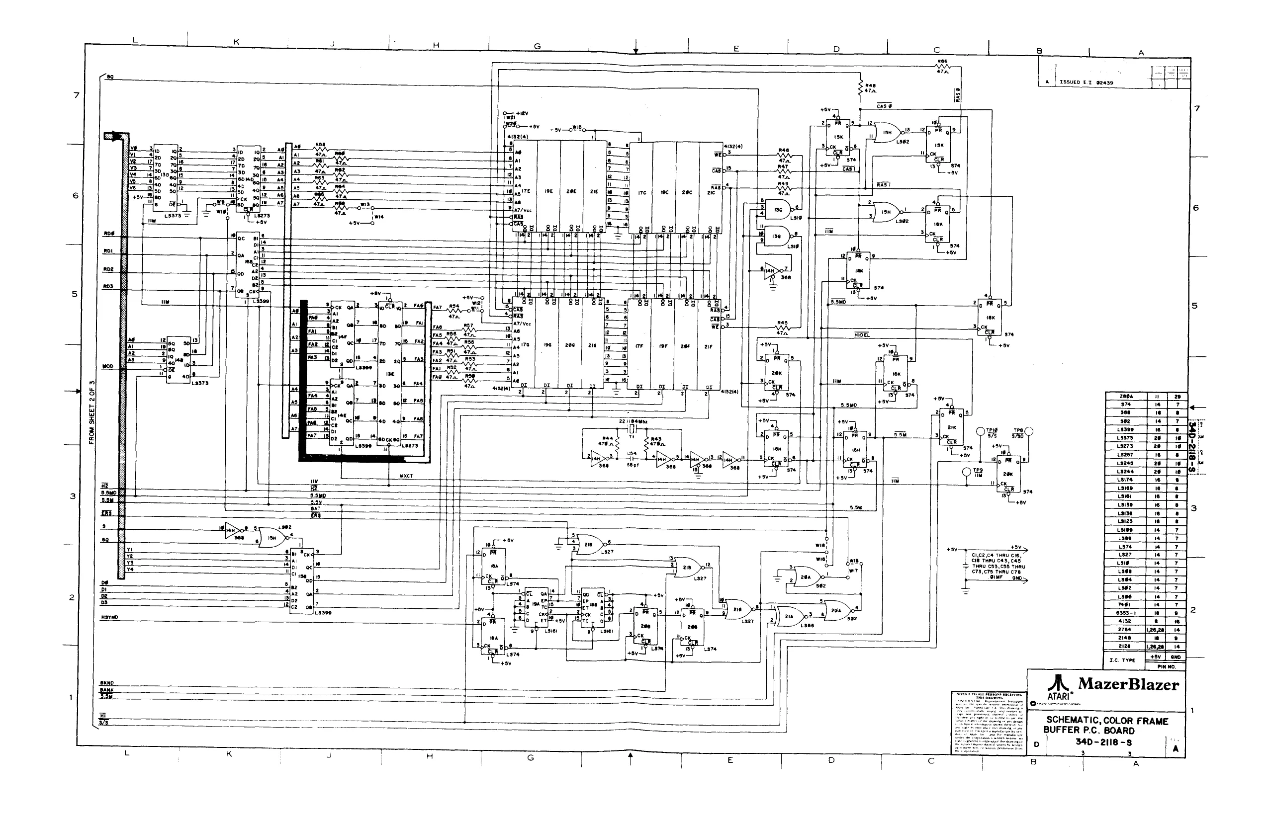
SCHEMATIC, COLOR FRAME. BUFFER P.C. BOARD
This page reads as a drawing: its text was drawn rather than typeset, and comes out in fragments. See the original scan.
This page reads as a drawing: its text was drawn rather than typeset, and comes out in fragments. See the original scan.
This page reads as a drawing: its text was drawn rather than typeset, and comes out in fragments. See the original scan.
This page reads as a drawing: its text was drawn rather than typeset, and comes out in fragments. See the original scan.
TSsueo Ex o2aed
Te ax 220.0 RE, RSS 2200. Syne ae YSN
aaa Ja lus Iwo |
TT Jo bw Jo
SPARE GATES
ea Sot
yl FI ES
| or | pcan | 29, |
| bs | 7}to Sale | = |
| oo | leo le | PAS |
| a | 32 sol? | ss |
| a | ene ele | Rn |
| oO | ried 19 | ARE 220.0. |
Fd 220.0
| oe | He Se | me |
i! ye 226 cx. Tal MNN aes very te eet
or ra te
rH ee
ci B
‘| | & ae z af
L K J i H. | GS | 4 | £ | [e} c | [=} | A RESET TF, auuie nes 6 T inté® | a_[ rssuen ex o24ai LT
i a] i i i wie} Aw 34iw24,
i w| os
pe 12, R22 pal ass
Pa 3 (s32_ Ins)
£ “tT “4 ‘PORT NOTE: m ay Te T roaadng 1s wooten on vest dvs ¥ al 26] Ne. 3, MF 33K" AUoIO UNRES ly rr SPARE GATES
H q i
- Ass
SPEECH,
FROM SHEET | OF 2
[apes
ner Tae 2 om fate } seer
awn SUL vwenive cata HL ze rye rev Lone [env
wos2 a ie AX MazerBlazer 3 ATARI YZ ‘dia achinea 1
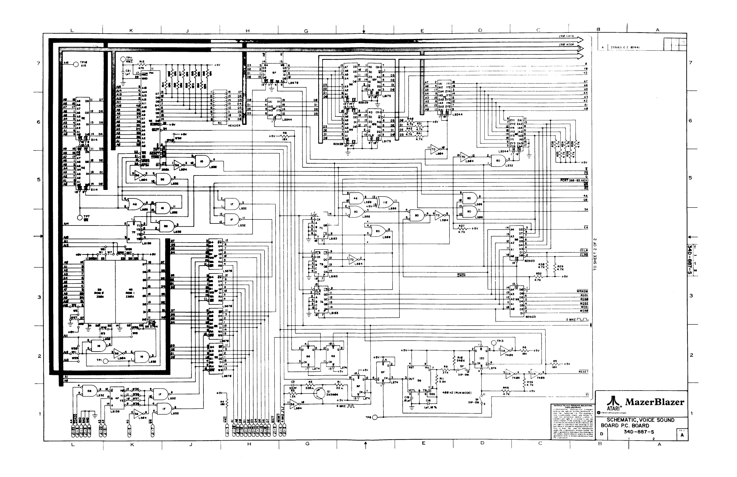
SCHEMATIC, VOICE AND
& SOUND BOARD PC. BOARD
D 340-887-S A 27 UL 2 2 B A
This page reads as a drawing: its text was drawn rather than typeset, and comes out in fragments. See the original scan.
NOTES
FOR 120 VAC LINE , CONNECT XFMR LEADS 1 TO. 3 ANG2 TO 4
FOR 24@ VAC LINE, CONNECT XFMR
Lead 2 TOS.
ae
HSA-1400 a
(CABINET)
CARD CAGE.
1 eno 2 41ZV UNREG 8] a +l 3 14v le SPR 7 +5V fever CRF-I@@) 2|
3]
6] SERVICE SWITCH (IF useD) nots” 5 loom
a #44 BuLes cc)
ZPU-2880 JP z3 Pw 186 CTRS RIBBON
Wein ibe cree
By, opin 36 crRs ry Fri ise eras Ls emf 2 pw he cree
com
44 bu
COIN DOOR ASSEMBLY
ean ‘arin i36.ctRS
}