Battlezone DP-156-2nd-01A
Battlezone (rev 2) (Atari, 1980) · Drawing Package · 1 pages · original scan
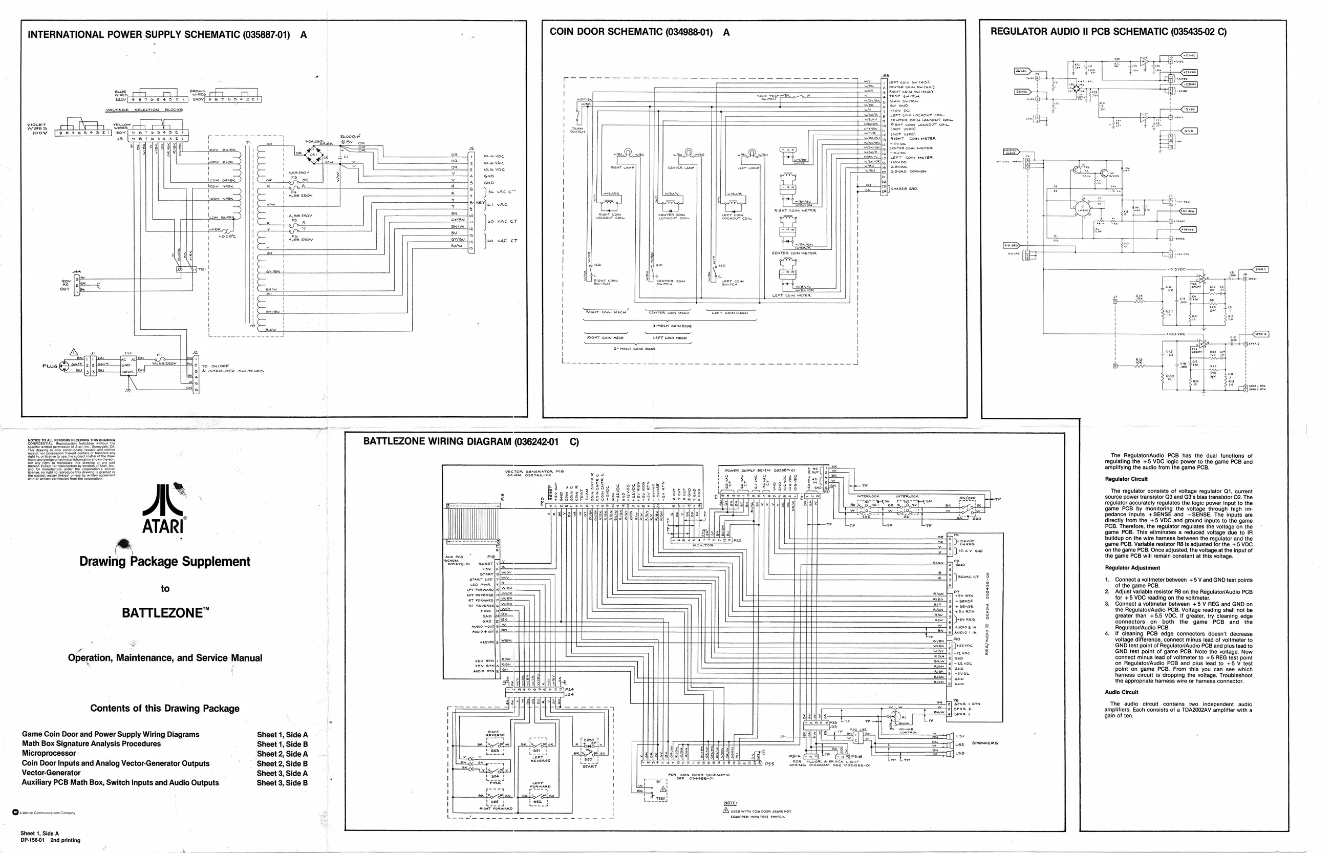
INTERNATIONAL POWER SUPPLY SCHEMATIC (035887-01) A
Siaee [OL . emets mn eae eT ese set] uel se ress ser
om 1 (cov [yetesss ey] wor
=i
i> EE
phytases tle
Drawing Package Supplement
to
BATTLEZONE™
Operation, Maintenance, and Service Manual
Contents of this Drawing Package
Game Coin Door and Power Supply Wiring Diagrams Sheet 1, Side A Math Box Signature Analysis Procedures Sheet 1, Side B
Microprocessor Sheet 2, Side A Vector-Generator Sheet 3, Side A
Coin Door Inputs and Analog Vector-Generator Outputs Sheet 2, Side B
Auxiliary PCB Math Box, Switch Inputs and Audio Outputs Sheet 3, Side B
‘Sheet 1, Side A DP-5601 2nd printing COIN DOOR SCHEMATIC (034988-01) A
BATTLEZONE WIRING DIAGRAM (03624201 C)
REGULATOR AUDIO Il PCB SCHEMATIC (035435-02 C)
Rea/nuoe senem osseas-c8 ‘The Regulator/Audio PCB has the dual functions of regulating the +5 VDC logic power to the game PCB and amplifying the audio from the game PCB.
Regulator Circuit
‘The regulator consists of voltage regulator Qt, current source power transistor Q3 and Q3's bias transistor G2. The ‘game PCB by monitoring the voltage through high im: Pedance inputs +SENSE and ~SENSE. Tho inputs are tect from the, +8 VDC and ground inputs tothe game CB. Therefore, he regulator regulates the voltage on the fume FOB, Ths tiinates 9
‘on the game PCB. Once adjusted, the voltage atthe input of the game PCB will remain constant at this voltage.
Regulator Adjustment
- Connect a voltmeter between +5 V and GND test points of the game PCB.
- Adjust variable resistor RB on the Regulator/Audio PCB. for +5 VDC reading on the voltmeter.
- Connect a voltmeter between +5 V REG and GND on the Regulator/Audio PCB. Voltage reading shall not be greater than +55 VOC. If greater, try cleaning edge Connectors on both the game PCB and the Regulator/Audio PCB.
- If cleaning PCB edge connectors doesn't decrease voltage difference, connect minus lead of voltmeter to GND test point of Regulator/Audio PCB and plus lead to GND test point of game PCB. Note the voltage. Now Connect minus lead of voltmeter to +5 REG test point fon RegulatoriAudio PCB and plus lead to +5 V test point on game PCB. From this you can see which harness circuit is dropping the voltage. Troubleshoot the appropriate hamess wire or hamess connector.
‘Audio Cireuit
The audio circuit contains two independent audio amplifiers. Each consists of a TOAZOO2AV {gain of ten,