Dig Dug TM-203 3rd Printing
Dig Dug (mini arcade) (Basic Fun, 2018) · Technical Manual · 68 pages · 61 sections · original scan
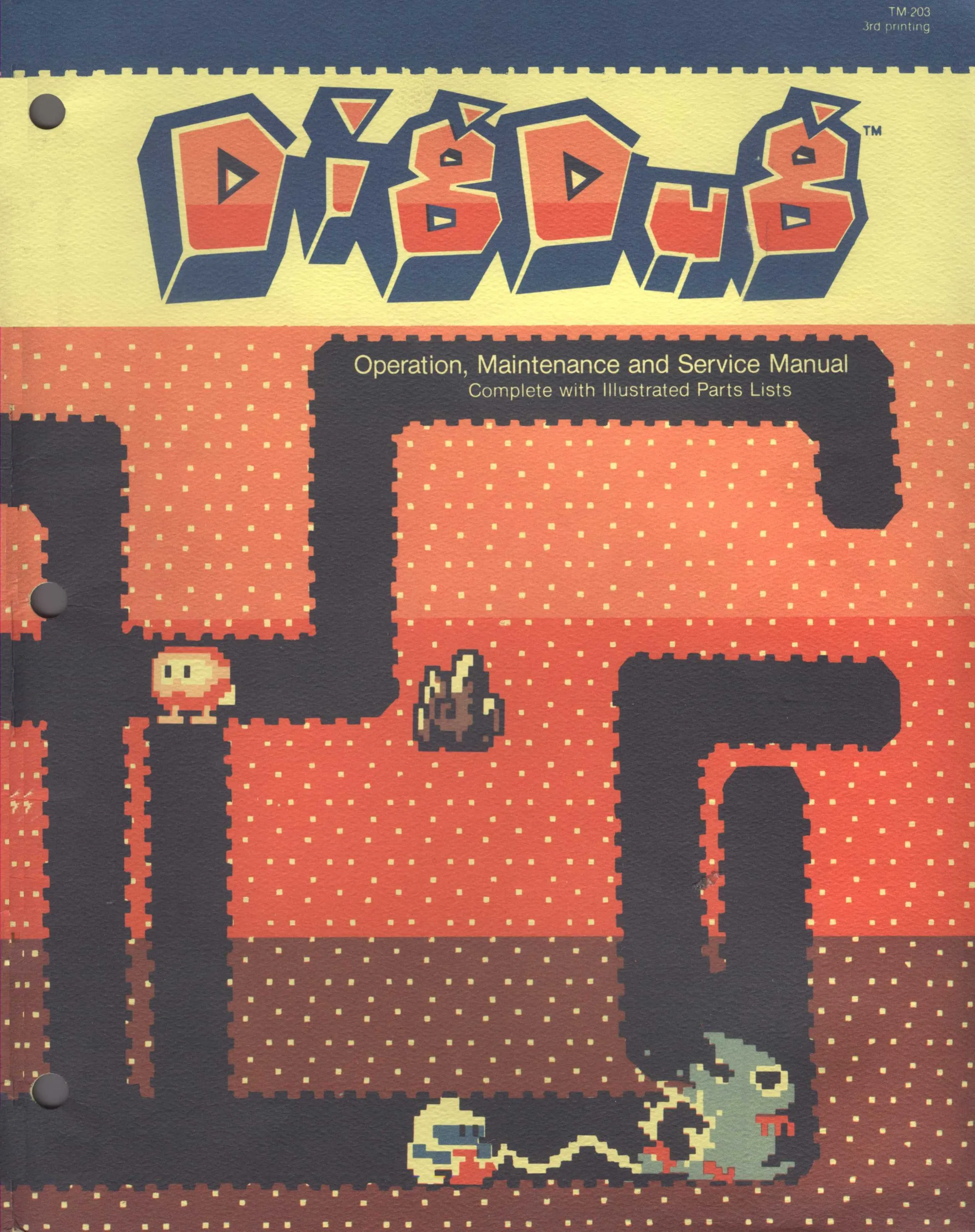
This page is a drawing, shown as the original scan.
GAME SERIAL NUMBER LOCATION
Your game's serial number is stamped on a label on
The same number is also on the chassis of
Operation, Maintenance and Service Manual
Complete with Illustrated Parts Lists
Engineered and Designed by NAMCO, LTD. Manufactured under license by ATARI, INC.
Dig Dug™
© 1982 by Atari, Inc. All rights reserved. No part of this publication may be reproduced by any mechanical, photographic, or electronic process, or in the form of a phonographic recording, nor may it be stored in a retrieval system, transmitted, or otherwise copied for public or private use, without permission from the publisher.
The Dig Dug™ game play, all graphic designs, this technical manual, its accompanying schematic diagrams, and the display manual are protected by the new Copyright Act of 1976.
This Act provides for increased penalties for violating federal copyright laws. Courts can impound infringing articles while legal action is pending. If infringers are convicted, courts can order destruction of the infringing articles.
In addition, the Act provides for payment of statutory damages of up to $50,000 in certain cases. Infringers may also have to pay costs and attorneys' fees, fines up to $25,000, and face an imprisonment of up to one year.
Atari will aggressively enforce its copyrights against any infringers. We will use all legal means to immediately halt any manufacture, distribution or operation of a copy of video games made by us. Anyone who purchases such copies risks forfeiting such a game.
Published by: ATARI INC. 790 Sycamore Drive PO. Box 906 Milpitas, California 95035
Lithographed in the U.S.A. 5L
Dig Dug™
to licensed communications services is not permitted by the FCC (Federal Communications Commission) If you suspect interference from an ATARI game at your location, check the following: @ All grounds (green wires) in the game are properly connected as shown in the game wiring diagram, and @ The game’s power cord is properly plugged into a grounded 3-wire outlet. If you are unable to solve the interference problem, please contact:
ATARI Customer Service (800) 526-3849 or (800) 538-1611
Notice Regarding Non-ATARI Parts
Use of non-ATARI parts or modifications of your ATARI game circuitry may adversely affect the safety of your game, and may cause injury to you and your players.
The warranty printed on the inside back cover of this manual may be voided, if you do any of the following:
@ you substitute non-ATARI parts in your coin-operated game, or
@ you modify or alter any circuits in your ATARI game by using kits or parts not supplied by Atari.
Not only may the use of any non-ATARI parts void your warranty, but any such alteration may also adversely affect the safety of your game and may cause injury to you and your players.
Dig Dug™
Table of Contents
Set-Up Procedures A. New Features... 2... cee cece een teen eeeee 1-3 B. Opening the Cocktai 1-4 C. Gamelnspection ........ 1-5 D. Game Installation 1-5
- Installation Requirements . 1-5
- Voltage Selection ..... 1-5 E. Cocktail Table Legs . 16 F. Switch Locations . 17
- On/Off Switch . see 1-7
- Utility Panel Switches . . 1-7
- Option Switches .... 18 G. Option Switch Settings . H. Self-Test Procedure Game Play . Attract Mode... . . Ready-to-Play Mode . . Play Mode , High Score Mode . Hints for Game Play OPpons
Troubleshooting A. Introduction «00.6... eee nce ete ere eee t teens 24 B. Comments on Troubleshooting . oe C. Self-Test Procedure .......... cece ccc tee eens 22
Maintenance, Repair and Parts Cabinet-Mounted Assemblies ............0 00sec cece eet eee ee 3-2 The Control Panel ......... Fluorescent Tube and Speaker . Onmoop> Video Display ........... .. 3-18 Coin Doors ...... 3-20 Printed-Circuit Boards . -. 3-25 Power Supply Assembly ... Seg sae ete gis ee ae ences 3-32
Dig Dug™
List of Illustrations
Figure 1-1 Game Overview, Upright Cabinet 1-2 Game Overview, Cabaret Cabinet 1-3 Game Overview, Cocktail Cabinet 44 Figure 1-2 Adjusting the Table Legs . 16 Figure 1-3 Game Switch Locations, Upright and Cabaret Cabinets ........... 1-7 Game Switch Locations, Cocktail Cabinet .............0..0eeeee 18 Figure 1-4 Self-Test Procedure .. 0.0.0... eee eee cece eee 1-11
Figure 2-1 Self-Test Screen 1—Test Passes. ........- 60... cece eee eee ee 2-2 Figure 2-2 Self-Test Screen 1—Test Fails. wee BB Figure 2-3. Self-Test Screen 2 23
Maintenance, Repair and Parts: Figure 3-1 Cabinet-Mounted Assemblies, Upright Cabinet 3-2 Cabinet-Mounted Assemblies, Cabaret Cabinet . 3-4 Cabinet-Mounted Assemblies, Cocktail Cabinet 3-6 Figure 3-2 The Control Panel 3-11 Figure 3-3 Control Panel Assembly . 3-12 Figure 3-4 Joystick Assembly. .........0. 0. cece eee reece eens 22 O14
Figure 3-5 Fluorescent Tube and Speaker, Upright Cabinet Figure 3-6 Video Display, Upright and Cabaret Cabinets Video Display, Cocktail Cabinet ........ Figure 3-7 Vertical-Mounted Coin Door, Upright and Cabaret Cabinets Figure 3-8 Double Coin Acceptor/Mount Assembly, Cocktail Cabinet . Figure 3-9 Printed-Circuit Board Removal Figure 3-10 Dig Dug™ Game PCB Assembly . Figure 3-11 Regulator/Audio I|PCB Assembly . Figure 3-12 Power Supply Assembly
Table 1-1 Game Price and Bonus Options Table 1-2. Game Difficulty, Price and Special Options . Table 1-3. Dig Dug Scoring
Dig Oug™
If reading through this manual does not lead to solving a certain maintenance problem, call TELEHELP® at the Atari Customer Service office in your geographical area, as shown below.
WEST and CENTRAL U.S.A. Service only
Atari, Inc. California Customer Service Office 1105 N. Fair Oaks Avenue P. O. Box 427, Sunnyvale, CA 94086 Telex 17-1103 (Monday-Friday, 7:30-4:00 pm Pacific Time) From California, Alaska, or Hawaii @ (408) 745-2900 Service from anywhere in the area shown in white @ oltiree (800) 538-1611
EAST U.S.A. Service only
Atari, Inc. New Jersey Customer Service Office 12A World's Fair Drive, Somerset, NJ 08873 Telex 37-9347 (Monday-Friday, 7:30-4:00 pm Eastern time) From New Jersey ®F (203) 469.5993 s From anywhere else in this area toll-free (800) 526-3849
EUROPE Service only
Atari Ireiand Limited European Customer Service Office Tipperary Town, Ireland Telex 28165 TIPPERARY TOWN, (Monday-Friday, 9:00-6:00 pm GMT) IRELAND
@ 6252155
Set-Up Procedures
How to Use This Manual
This manual, written for game operators and service technicians, describes the Dig Dug™ game.
The manual contains information about ai// Dig Dug cabinets. Whenever information is unique to
the Upright cabinet, this symbol appears: i
Whenever information is unique to the Cabaret™ cabinet, this symbol appears: /,
Whenever information is unique to the Cocktail cabinet, this symbol appears: =
\ ae
ig (> "~ Chapter One includes new features, game set-up, option switch settings, self-test procedures and game play.
Chapter Two details troubleshooting procedures.
Chapter Three contains maintenance, repair and parts information. In addition, schematic diagrams of the game circuitry are included with this manual. Figures 1-1 and 3-1 illustrate the game cabinet. Italicized lettering on these figures refers you to other places in the manual for information about specific cabinet parts.
Chapter
Set-Up Procedures Dig Dug™
FLUORESCENT TUBE AND SPEAKER See Figure 3-5
COLOR VIDEO DISPLAY See Figure 3-6
: JOYSTICK
See Figure 3-4 ACCESS PANEL
CONTROL PANEL See Figure 3-2 & 3-3
GAME PCB See Figures 3-9 & 3-10
COIN DOOR See Figure 3-7
POWER SUPPLY UTILITY PANEL See Figure 3-12 See Figure 13
Figure 1-1 Game Overview
Upright Cabinet
+2
Dig Dug™ Set-Up Procedures
A. New Features
The Dig Dug™ game has two new features. Even if @ Game Sounds. There are 21 different game you're familiar with ATARI® games, you should note sounds. In addition, a special option switch setthese important differences: ting lets you hear sounds used during game @ Joystick Control. This new four-position control play, but turns off attraction-mode sounds. is made of steel and molded plastic. It has few New features, as well as all other major parts in parts, which makes servicing easier. The leaf the game, are illustrated in Figure 1-1. Throughout switches snap in and out for easy replacement. this manual, wherever one of these new features is The rubber bellows is designed for a quick re- mentioned, you will see this symbol: turn to center.
COLOR = ; ACCESS PANEL VIDEO DISPLAY fe : | See Figure 3-6 Le 2 |
JOYSTICK : Bees U REGULATOR! AUDIO li PCB See Figure 3-4 See Figures 3-9 & 3-11
CONTROL PANEL See Figures 32 & 3-3
COIN DOOR See Figure 3-7
UTILITY PANEL See Figure 1-3
GAME PCB See Figures 3-9 & 3-10
POWER ON/OFF SWITCH
POWER SUFPLY See Figure 312
Figure 1-1 Game Overview, continued
Cabaret™ Cabinet
1-3
Set-Up Procedures Dig Dug™
B. Opening the Cocktail Cabinet
- Opening the Table Top @ The access panel near the bottom of the cabinet @ To open the game cabinet, unlock and open the will then come out. two key locks at one end of the game cabinet, located immediately below the table top (see 3. Closing the Table Top Figure 1-1). . @ To close the cabinet, stand opposite the hinged @ Carefully lift the table top until the support arm ; i locks into place. Do not jam the table top at the yourrightiien and grasp the table top with end of its upward swing. . @ With your left hand, press the button at the mid-
- Access Panel dle of the support arm and push the button out . toward the left. @ To open the access panel, lift out the steel sec- age urity bar that secures the panel to the cabinet ©@ Gently lower the table top to the closed position. wall. @ Lock both key locks.
TABLE TOP
GAME PCB COLOR See Figures 3-9 & 3-10 VIDEO DISPLAY
ay See Figure 3-6
JOYSTICK See Figure 3-4 UTILITY PANEL See Figure 1-3
SUPPORT ARM
CONTROL PANEL See Figures 3-2 & 3-3
SECURITY BAR REGULATORI
AUDIO II PCB See Figures 3-9 & 3-11
ACCESS PANEL SPEAKER
START SWITCH
COIN ACCEPTORS See Figure 3-8
POWER SUPPLY See Figure 3-12 COIN COUNTER
ADJUSTABLE LEG POWER ONIOFF SWITCH
See Figure 1-2 Looe See Figure 1-3
Figure 1-1 Game Overview, continued Cocktail Cabinet
+4
Dig Dug™
C. Game Inspection
Please inspect your game carefully to insure that it was delivered to you in good condition.
- Examine the exterior of the game cabinet for dents, chips, or broken parts.
- Remove the screws that were used as extra security to seal the rear access panel (Upright and Cabaret cabinets). Unlock and open this panel or the Cocktail table top, and the coin door; inspect the interior of the game as follows: @ Check that all plug-in connectors (on the game harness) are firmly seated. Replug any connectors found unplugged. Don’t force connectors together. The connectors are keyed so they only go on in the proper orientation. A reversed edge connector will damage a PCB and will void your warranty. @ Check that all plug-in integrated circuits on the PCBs are firmly seated in their sockets. @ Remove the iie-wrap that holds the coiled power cord on the inside cabinet wall (Upright and Cabaret cabinets). Check the power cord for any cuts or dents in the insulation. Piace the square black plastic strain-relief plate in the wood slot at the bottom of the rear panel opening.
@ Note the game’s serial number. On Upright and Cabaret cabinets, it is printed on a label on the back of the cabinet. On the Cocktail cabinet, the label is located on the start switch side of the cabinet. Verify that the same serial number is also on the Dig Dug game PCB, Regulator/Audio ll PCB, power supply and video display. A drawing of the serial-numbered components is on the inside front cover of this manual. Please mention this number whenever you call your distributor for service. @ Check major subassemblies, such as the power supply, control panel and video display, for secure mounting. Set-Up Procedures
D. Game Installation
- Installation Requirements
Power 175 watts Temperature 0 to 38°C (32 to 100°F) Humidity Not over 95% relative Upright Cabinet 64 x 79 cm (25% x 34 in.) 174 cm (68% in.) Cabaret Cabinet 52 x 78% cm (20% x 31 in.) 153% cm (6042 in.) Cocktail Cabinet 62% x 822 cm (24 V2 x 32 V2 Space Required Game Height
Space Required Game Height
Space Required in.) Game Height 65 x 101 cm (25% x 39% in.)
- Voltage Selection The power supply used in this game operates on the line voltage of almost any country in the world. The power supply comes with either one, two, or three different voltage selection plugs. Plug voltages and wire colors are 100 VAC (violet wire colon), 120 VAC (yellow wire color), 220 VAC (blue wire color), and 240 VAC (brown wire color).
Before plugging in your game, check your line voltage. Then check the wire color on the voltage selection plug that is plugged into your power supply. Make sure the voltage selection plug is correct for your location’s line voltage (see Figure 3-12).
o y=
Set-Up Procedures Dig Dug™
E. Cocktail Table Legs
1-6 Remove or empty the coin box to prevent loose coins from sliding out of the box and into the game cabinet. Lay the table on end as shown. Place a ‘support (the coin box, books or tool box) under the recessed side of the cabinet. Remove the two Allen-head screws on each leg. Grasp the legs and slide them into the desired position. Then replace the screws.
E COIN BO:
REMOVE CO! Xx USE TWO SCREWS
WHEN ATTACHING EACH TABLE LEG!
Ss
39% in.
30in.
27% in.
SHIPPING POSITION (25% in)
Figure 1-2 Adjusting the Table Legs
Dig Dug™
F. Switch Locations
- On/Off Switch The Upright and Cabaret cabinet on/off switch is located on the back of the cabinet, lower left side. The Cocktail cabinet on/off switch is located on the bottom of the cabinet (see Figure 1-3). Set-Up Procedures
- Utility Panel Switches For Upright and Cabaret cabinets, the utility panel includes the volume control, self-test and coin switches, and coin counter. The coin switch is used to credit the game without tripping the coin counter. These switches are located inside the upper coin door (see Figure 1-3).
UTILITY PANEL:
COIN COUNTER
SELF-TEST
VOLUME CONTROL (To increase, turn clockwise)
POWER ON/OFF SWITCH OPTION SWITCHES: SWITCH AT 2C/D (Game price and bonus options) SWITCH AT 2C (Game difficulty, price and special options)
Figure 1-3 Game Switch Locations
Upright and Cabaret Cabinets
Set-Up Procedures Dig Dug™
OPTION SWITCHES: SWITCH AT 2C/D (Game price and bonus options) SWITCH AT 2c (Game difficulty, price and special options)
COIN VOLUME CONTROL (To increase, tum clockwise) SELF-TEST
UTILITY PANEL:
POWER ON/OFF SWITCH “ (Reach under game. to activate switch)
Figure 1-3 Game Switch Locations, continued Cocktail Cabinet
- Option Switches For the Cocktail cabinet, the utility panel inciudes Option switches, for all game cabinets, are locathe volume control, self-test and the coin switches. ted on the game PCB as follows: These switches are located under the table top. To @ Game price and bonus options are at PCB localocate the coin counter, remove the coin box (see tion 2C/D. Figure 3-1). : @ Game difficulty, price and special options are at PCB location 2C.
Dig Dug™ Set-Up Procedures
G. Option Switch Settings
Tables 1-1 and 1-2 detail game options and their settings. Options are preset at the factory and shown by the $ symbols. However, you may change the settings to suit your individual needs.
Table 1-1 Game Price and Bonus Option Settings The &toggle switch at location 2C/D is accessible when the Dig A “coin” is defined as 25¢, 1DM or 1Fr. If you have a 2DM/1DM. Dug™ game PCB is mounted in place. To change switch settings, or 2Fr/1Fr coin door with two coin counters, set switch 8 at PCB set the self-test switch to on. Verify the changes on the self-test location 2C to off. Then different denominations are counted on screen. Then turn the self-iest switch to off. the two coin counters.
Settings of 8-Toggle Switch on Dig Dug PCB (at 2C/D)
| 8 | 7 | 6 | 4 | 3 | 2 | 1 | Option |
| On | On | 1 Dig Dug life | |||||
| On | Off | 2 Dig Dug lives | |||||
| Off | On | 3 Dig Dug lives | $ | ||||
| Off | Off | 5 Dig Dug lives |
Bonus lives awarded at the following point values: With 1, 2 or 3 Dig Dug lives With 5 Dig Dug lives
| On | On | On | No Bonus | No Bonus |
| Off | On | On | First at 10,000, | First at 20,000, |
second at 40,000, second at 60,000, and every 40,000 $ and every 60,000
| On | Off | On | First ai 10,000, | First at 30,000, |
second at 50,000, second at 80,000, and every 50,000 and every 80,000
| Off | Off | On | First at 20,000, | First at 20,000, |
second at 60,000, second at 50,000 and every 60,000
| On | On | Oft | First at 20,000, | First at 20,000, |
second at 70,000, second at 60,000 and every 70,000
| Off | On | Off | First at 10,000, | First at 30,000, |
second at 40,000 ‘second at 70,000
| On | Off | Off | First at 20,000, | First at 20,000 |
second at 60,000
| Off | oft | Off | First at 10,000 | First at 30,000 |
Right coin mech—coin doors with 1 or 2 coin counters*
| On | On | On | 1 coin for 7 credits | |
| Off | On | On | 1 coin for 6 credits | |
| On | Off | On | 1 coin for 3 credits | |
| Off | Off | On | 1 coin for 2 credits | |
| On | On | Off | 1 coin for 1 credit | $ |
| Olt | On | Off | 2 coins for 3 credits | |
| On | Off | Off | 2 coins for 1 credit | |
| Off | Off | Off | 3 coins for 1 credit |
$Manufacturer's suggested settings *See Table 1-2 for left coin mechanism.
Set-Up Procedures Dig Dug™
Table 1-2 Game Difficulty, Price and Special Options The table below contains the switch settings for options relating to game difficulty, price and special options. The switches, ‘on the game PCB at location 2C, are accessible when the PCB is mounted in place. Aspecial option allows for continuation of game play. If a player is at a more advanced round when his game ends, he has 16 seconds to begin the next game at the same round. Another special Option allows you to freeze the game action.
Settings of 8-Toggle Switch on Dig Dug PCB (at 2C) 7 5 4 3 2 8 6 1 Option
On Off
On On On Off
Off On
Off Off On Off On Off
Off On
On On Off Off One coin counter $ Two coin counters*
A—Easy game difficulty B—Medium game difficulty $ C—Hard game difficulty D—Expert game difficulty Continuation of game play $ ‘No continuation of game play Attract Mode sound $ No Attract Mode sound Normal game action $ Freeze game action
Left coin mech—coin doors with 2 coin counters On 1 coin for 1 credit $ Off 1 coin for 2 credits On 2 coins for 1 credit Off 2 coins for 3 credits
$Manufacturer’s recommended settings *Coin doors with different denominations and two coin counters.
H. Self-Test Procedure
This game will test itself and provide data to show that the game’s circuitry and controls are operating properly. The data is provided on the video display and speaker. No additional equipment is necessary.
We suggest you perform the self-test procedure when you first set up the game, any time you collect money from the game, when you change game options, or when you suspect game failure.
Refer to Figure 1-3 for the location of the self-test switch and option switches. To perform the self-test, set the self-test switch to on. After about eight seconds the self-test screen will be displayed.
To see game statistics, press the utility coin switch. To reset the high score table, simultaneously push and hoid the pump and utility coin switches for 10 seconds. To end the self-test, set the self-test switch to off.
The complete self-test procedure is explained in Chapter 2, Self-Test Procedure. |f any part of the test described in Figure 1-4 fails, refer to Chapter 2. ~ P10,
Dig Dug™ Set-Up Procedures
Figure 1-4 Self-Test Procedure
Instruction Test Passes
- Set the self-test switch to on (see Figure 1-3). Patterns appear on the screen. After about 8 seconds, the screen displays the picture below. The RAMs, ROMs and other chips are tested. 'f the picture is different from the picture below, refer to Chapter 2, Self-Test Procedure.
- Activate any control panel switch. Game sounds are produced, from SOUND 00 through SOUND
- Activating any control panel switch produces a ney sound. Test ail switches this way. Ii test fails, refer to Chapter 2, Self Test Procedure. Game sounds:
Se SOUND 00 Credit issued
SOUND 07 Start of game SOUND 02 Indication of highest score SOUND 03 Game over SOUND 04 Monster attacking Dig Dug SOUND 05 Dig Dug dies SOUND 06 Monster escaping SOUND 07 Bonus Dig Dug awarded SOUND 08 End of wave SOUND 09 Monster speeding up SOUND 10 Monster crushed by rock SOUND 11 Monster bursting SOUND 12 Rock hitting ground SOUND 13 Rock falling SOUND 14 Dragon spitting fire SOUND 15 Dig Dug throwing harpoon SOUND 16 Dig Dug pumping up monster
SOUND 17 Dig Dug walking SOUND 18 Monster moving SOUND 79 Dig Dug capturing vegetable SOUND 20 Enter initials into high score table
ALL RAMS GOOD
ALL ROMS GOOD ~=RAM OK
TYPE OF hie
CABINET —> UPRIGHT
1 COIN 1 CREDIT
1 COIN 1 CREDIT
DIGDUG 3 LEFT COIN MECH
RIGHT COIN MECH
NO. OF LIVES
DIFFICULTY
SOUNDS 1ST BONUS FOR 10000 PTS 2ND BONUS FOR 40000 PTS ~<«— BONUS LEVELS GAME STATISTICS: AND FOR EVERY 40000 PTS THE COUNT STARTS AT 999999) AND DECREASES. For example, if you play 10 games, the game subtracts 10 from = 99 .9999 .9999 .9999 .9999. 999 and the display shows 98.9 for the number of games played. (Disregard decimal points)
NO.OF GAMES NO.OF POINTS NO. OF SECONDS NO. OF BONUS PLAYED {times 10) PLAYED LIVES AWARDED
v1
Set-Up Procedures
I. Game Play
The Dig Dug™ game is a one- or two-player game with a color raster-scan video display. The screen shows a cutaway view of the land, most of which is below ground. The piayer controls the Dig Dug character who travels through and digs tunnels in the dirt. The object is for Dig Dug to destroy monsters by pumping them up or dropping rocks on them and to capture vegetables.
The third picture simulates game play. Dig Dug walks through underground tunnels. Monsters chase him and he periodically pumps them up or drops rocks on them. This picture ends when Dig Dug is destroyed.
- Attract Mode The attract mode begins when power is applied to the game, after a play or high-score mode, or after self-test. This mode is continuous and stops only when a credit is entered, or when in self-test. This mode may last for about one minute and fifteen seconds. in the attract mode, the screen displays one of four possible pictures.
In the first picture, Dig Dug enters the screen from the top right and walks across the surface. He digs a tunnel into the ground and begins to dig around the words DIG DUG. Meanwhile, monsters escort the word ATARI across the top of the screen. When Dig Dug digs entirely around the words DIG DUG, these words, ATARI and the monsters fall down to anew position on the screen. Everything in the picture rolls up except the words DIG DUG.
In the second picture, game characters appear on the screen. Dig Dug is between FYGAR, the firebreathing dragon, and POOKA, the fat monster. First, Dig Dug pumps up POOKA until he explodes and disappears, and 200-500 (points) appears in his place. Then, Dig Dug pumps up FYGAR until he explodes and disappears, and 200-1000 appears in his place.
The third picture simulates game play. Dig Dug walks through underground tunnels. Monsters chase him and he periodically pumps them up or drops rocks on them. This picture ends when Dig Dug is destroyed.
The fourth picture shows the high-score table. The top five scores, round played and matching initials appear on the screen.
During the attract mode, the high score and score(s) for one or both players appear at the top of the screen. Credits or number of Dig Dug lives and
4-12 Dig Dug™
the round number appear at the bottom of the screen, This mode ends when coins are inserted and accepted for game play.
- Ready-to-Play Mode
During this mode, the high score and score(s) for one or both players appear at the top of the screen. The words PUSH START BUTTON, 1 PLAYER ONLY or 1 OR 2 PLAYERS and bonus life information appear in the center of the screen. ATARI copyright, credits and the round number appear near the bottom of the screen. This mode ends when a player pushes the start button.
- Play Mode
This mode begins when Dig Dug enters the screen from the top right and walks across the surface. He digs down to the center of the screen. The words PLAYER 1 READY or PLAYER 2 READY ap- Pear on the screen. Also, high score and score(s) for one or both players appears at the top of the screen. The number of Dig Dug lives and the round number appear at the bottom of the screen.
Game play takes place on a cutaway section of the land. The characters are Dig Dug and two monsters, one of which is a fire-breathing dragon. The underground area is divided into four different colored layers of dirt. Rocks are scattered in the dirt. The sky is at the top of the screen.
The player controls Dig Dug. He moves through horizontal and vertical tunnels. When Dig Dug digs new tunnels he moves slowly. When he is on the surface or in an existing tunnel, he moves faster. The object of the game is for Dig Dug to destroy all the monsters and go to the next round.
Dig Dug™
Monsters are trapped in caves. A monster may get out of a cave two ways. Dig Dug may dig him out. Then, the monster chases Dig Dug. The monster may also get out of the cave by turning into a ghost. As a ghost, he cannot be destroyed. The ghost does Not travel in the tunnels. He travels through the dirt, and can travel diagonally. However, he reappears as the monster when he goes into a tunnel.
The monster moves faster than Dig Dug in vertical tunnels and slower on the surface. He destroys Dig Dug by catching him. In addition, the dragon destroys Dig Dug by breathing fire on him. The dragon only breathes fire horizontally. The fire can penetrate the dirt.
Dig Dug destroys the monsters by pumping them up until they burst, or by causing rocks to drop on them. To pump up and destroy a monster, the player presses and holds down the pump button. It is possible to stun a monster for a few seconds by pressing the pump button once or twice. While a monster is stunned, Dig Dug may pass over him without being destroyed. If two monsters are very close together, only one may be stunned. The other will catch and destroy Dig Dug.
Dig Dug must dig tunnels under the rocks to get them to drop. A rock may fall in a vertical or a horizontal tunnel. A rock also goes through a thin layer of dirt from one tunnel to the next. In a vertical tunnel, Dig Dug may stay directly under a rock and it will not drop. However, in a horizontal tunnel, Dig Dug must move out from under a rock right away, or he will be crushed.
After two rocks are dropped, a vegetable (worth extra points) appears in a tunnel in the center of the
wa, Set-Up Procedures
screen. A player has 10 seconds to capture (touch) the vegetable or it will disappear. There is only one vegetable per round.
The game progresses by rounds. Round 1 starts with four monsters and three rocks. The vegetable is a Carrot. One flower on the surface (top right of the screen) represents Round 1. Two flowers represent Round 2, etc. As the rounds progress, the monsters move a little faster, and are better at avoiding falling rocks. In each round, the last monster tries to escape. If he is not caught by Dig Dug, he exits on the surface (top left).
The game ends when all of the Dig Dug lives are used up. A player may continue to play at the same round (level) by following instructions on the screen. He has 16 seconds to insert a coin(s). Then he must push and hold the pump and start buttons at the same time.
- High Score Mode
This mode begins when a player has one of the five top scores. A player enters his initials in the center of the screen. The initials are then transferred to the table. To reset the high-score table, set the self-test switch to on. Simultaneously push and hold the pump and utility coin switches for 10 seconds. Then set the self-test switch to off.
- Hints for Game Play
@ Get many monsters to follow you. Then dig a long vertical tunnel up to a rock. Drop the rock by digging right or left. @ Dig Dug may take extra time to turn. It is better to start turning early than to wait until the last second. @ Destroy monsters at bottom dirt level for more points. @ Use PUMP to stun monsters. Then you may escape or walk through them. @ Don’t stop next to dragon when he is in a cave. His fire can go through a thin layer of dirt and destroy you. @ A vegetable appears after two rocks have been dropped. So be sure to drop two rocks in each round.
Set-Up Procedures Dig Dug™
Table 1-3 Dig Dug™ Scoring
Bursting Monsters
Dirt Layer POOKA FYGAR*
| 1 | 200 | 400 |
| 2 | 300 | 600 |
| 3 | 400 | 800 |
| 4 | 500 | 1000 |
*Worth ‘2 amount vertically
Dropping Rocks Monsters
Destroyed Points
1 1000 2 2500 3 4000 4 6000 5 8000 6 10,000 7 12,000 8 15,000
Vegetables Points
Round Vegetable for Capture
| 1 | Carrot | 400 |
| z | Rutabaga | 600 |
| 3 | Mushroom | 800 |
| 4 | Cucumber | 1000 |
| 5 | Cucumber | 1000 |
| 6 | Eggplant | 2000 |
| 7 | Eggplant | 2000 |
| 8 | Bell Pepper | 3000 |
| 9 | Bell Pepper | 3000 |
| 10 | Tomato | 4000 |
| aa | Tomato | 4000 |
| 12 | Onion | 5000 |
| 13 | Onion | 5000 |
| 14 | Watermelon | 6000 |
| 15 | Watermelon | 6000 |
| 6 | Galaxian | 7000 |
| 17 | Galaxian | 7000 |
18 and above Pineapple 8000 Digging a new tunnel is worth 10 points per %, inch (1.61 cm).
Troubleshooting
A. Introduction
This game tests itself when the self-test switch is set to the on position. li there is a failure, the game produces audiovisual aids to help you isolate the failing portion of the game. The self-test procedure included in Chapter 1 is to help you decide if the game is or isn’t working properly. The expanded procedures in this chapter are included to help the qualified electronic technician determine why the game n isn’t working properly.
B. Comments on Troubleshooting
When troubleshooting, first determine the symptom(s) of the failure. After determining the symptom, Jook over the wiring diagram and determine what assemblies could cause the failure. Could it be caused by the power supply, Regulator/Audio II PCB, or the video display?
The next step is to check all harness wires and connectors to the suspected failing assembly. If you find no harness or connector problem, substitute an assembly known to be good for the suspected failing assembly. If the game functions properly, you have successfully isolated the failure. If it doesn’t, repeat the procedure with another assembly.
When you have isolated the failing assembly, you must troubleshoot that assembly and make the necessary repairs. If the display is failing, we suggest that a qualified video display technician handle the troubleshooting and repair. If the power supply or Regulator/Audio II PCB is failing, troubleshooting and repair is relatively simple, as these assemblies are not too complicated. If the game PCB is failing, troubleshooting and repair will greatly depend on your understanding of the operation of this PCB.
To effectively troubleshoot problems of the game PCB, it is necessary for you, the technician, to become familiar with the PCB’s hardware. The diagrams in the schematic package (included with the game) show the functions of the circuitry. Again, while troubleshooting this PCB, first determine the symptom of the failure, then locate the suspected area on the schematic diagram.
2-2 Dig Dug™
C. Self-Test Procedure
To enter Self-Test, set the self-test switch to the on position. Patterns appear on the screen. After about 8 seconds, the self-test screen is displayed (see Figure 2-1). See Chapter 1, Section H, Self-Test Procedure for a complete description of this part of the self-test.
RAM OK ROM OK UPRIGHT 1 COIN 1 CREDIT 1 COIN 1 CREDIT DIGDUG 3 RANK B SOUND 04 1ST BONUS FOR 10000 PTS 2ND BONUS FOR 40000 PTS AND FOR EVERY 40000 PTS
Figure 2-1 Self-Test Screen 1 Test Passes
Dig Dug™ Troubleshooting
To go to screen 2, set the self-test switch to off and immediately to on again.
SCREEN 2: Figure 2-2 Self-Test Screen 1 A white crosshatch pattern appears on the screen
Te Fai (see Figure 2-3). Use this pattern for convergence
est Fails (see the raster-scan video display manual).
SCREEN 1:
RAM FAILURE is indicated by the word RAM and a pair of alphanumeric characters displayed at the top of the screen. The following table lists the bad RAM chip and its location. Bad RAM chip location Screen Display on game PCB RAM OL. 9M RAM 0H 9M RAM iL 9M RAM 1H 9M RAM 2L 9E RAM 2H J/K RAM 3L SHI RAM 3H 9H RAM 4L. 9FIG RAM 4H. 9G/H
ROM FAILURE is indicated by the word ROM and anumber displayed at the top of the screen. The following table lists the bad ROM chip and its location.
Bad ROM chip location Screen Display ‘on game PCB ROM 1 6L ROM 2 6M ROM 3 6NIP ROM 4 6R ROM 5 6C ROM 6 6D =m St Figure 2-3 Self-Test Screen 2
2:3
This page carries no recoverable text. It is a drawing or a photograph. See the original scan.
Maintenance, Repair and Parts
In addition to maintenance and repair information, this chapter provides the necessary information for you to order parts for your Dig Dug game. Please note that common hardware has been deleted from most of the parts lists. This includes screws, nuts, washers, bolts, etc.
The parts lists are arranged in alphanumeric order. For example, all “‘A-” prefix numbers come first. Following this are numbers in sequence evaluated up to the hyphen, namely 00- thru 99-, then 000598-thru approximately 190000-.
When ordering parts, please give the part number, part name, applicable figure number of this manual, and serial number of your game. This will help to avoid confusion and mistakes in your order. We hope the results will be less downtime and more profit from your game.
Atari Customer Service numbers are listed in the front of this manual for your convenience.
Chapter
Maintenance, Repair and Parts Dig Dug™
A. Cabinet-Mounted Assemblies
Schematics, Self-Test Label & Manuals— see parts list on following page Fluor. Tube & Speaker Assy.— 036498-01 see Figure 3-5 (Upper Ret.) 038273-01 038274-01 ooreaaat (Attract. Giass/Graphics) (Shield) ramanas (FMolding)
Video Display— 003053-01 ¢ ae see Figure 3-6 (Lower Ret.)
Cx 78-6900402 (Grille) ; (Tape)
Control Panel Assy.— see Figures 32, 3-3 & 3-4
002465-01 (Coin Counter)
| ‘4038004-01 | i | 03741902 | ||
| (Util, Sw. Harn.) | 5 | ae | : | (Access Panel) |
| 69-001 | { | . | ||
| (Self-Test Sw.) | Z | 034536-03 |
178013-001 = = (Vibra, Damper) (Latch) 62.041 if
| I | (Coin Sw.) | | | f | ‘A038295-01 |
(Main Harn. Assy.) Game PCB Assy.— see Figures 29 & 3-10
| 49-9032 | : | : | 034536-02 |
| Coin Door Assy.— | (Vol. Ctrl.) | . | (Vibra. Damper) |
see Figure 3-7 A038297-01 g (Power Harn. Assy.) 038003-01
| (Util, Phi.) | = | (Caster) |
009992.01 (On/Oit Sw. Ovr.) A037491-01 (Coin Box)
A038256-01 Power Supply Assy.— (Cabinet Assy.) see Figure 3-12 A037470-01 (On/Off Sw.)
RegJAudio Il PCB Assy.— see Figures 3-9 & 3-4 78.3201 A037453.03, (Leg) A037454.03 & ‘A037455-03 (Power Cord) Figure 3-1 Cabinet-Mounted Assemblies Upright Cabinet
32 03827501
Dig Dug™ Maintenance, Repair and Parts
Figure 3-1 Cabinet-Mounted Assemblies, continued Upright Cabinet Parts List
Part No. Description A002465-01 6V Coin Counter
| A037453-03 | Strain-Relief Power Cord | (U.S.) |
| A037454-03 | Strain-Relief Power Cord | (Austria, Belgium, Chile, Denmark, Finland, France, Germany, Greece, |
Indonesia, Italy, Netherlands, Norway, Spain, Sweden, and Uruguay)
| A037455-03 | Strain-Relief Power Cord | (Australia and New Zealand) |
A037470-01 Power On/Off Switch and Mounting Plate Assembly A037491-01 Coin Box A038004-01 Utility‘Switch Panel Harness Assembly A038256-01 Cabinet Assembly (includes legs and PCB retainers, but not the rear access panel) A038295-01 Main Harness Assembly A038297-01 Power Harness Assembly The following four items are the technical information supplements to this game: SP-203 Dig Dug™ Schematic Package ST-203-01 Dig Dug Label with Self-Test Procedure and Option Switch Settings TM-160 Service Manuai for 19-Inch Electrohome Color Raster-Scan Display TM-203 Dig Dug Operation, Maintenance and Service Manual! 19-9032 Volume Control 62-041 SPDT Momentary-Contact Pushbutton Utility Coin Switch with Black Cap 69-001 DPDT Self-Test Switch
| 71-2110 | Lock Mechanism | (for rear access panel) |
78-3201 Cabinet-Leveling Leg 78-6900402 Vinyl Foam Single-Coated Adhesive Tape, Y%-Inch Wide x %-Inch Thick (24 in. required) 003053-01 Lower Attraction Glass Retainer 009992-07 On/Off Switch Cover
| 034536-02 | Foam Vibration Damper | (for Regulator/Audio 11 PC8) |
| 034536-03 | Foam Vibration Damper | (for Dig Dug Game PCB) |
036495-01 Speaker Grille 036498-01 Upper Attraction Glass Retainer 036686-01 Card of Game Pricing Labels (not shown in illustration)
| 037419-02 | Rear Access Panel | (does not include lock) |
| 037332-01 | Ventilation Grille | {/ocated on cabinet top) |
038003-01 Utility Switch Panel for Volume Control, Self-Test Switch, Coin Switch and Coin Counter 038273-01 Attraction Glass with Graphics 038274-01 Video Display Shield with Graphics 178013-001 Spring Draw Latch 178034-024 %-Inch Biack Plastic T-Molding 178048-001 2-Inch Rigid Caster
Maintenance, Repair and Parts Dig Dug™
Schematics, Self-Test Label & Manuals— see parts list on follo-ving page
A038321-01 037515-01 Video Display— (Cabinet Assy.) (Retainer) see Figure 3-6
03751102 71-2140 178034-024 (Lock) (FMolding}
Joystick Assy.— see Figure 3-4
Control Panel Assy.— see Figures 3-2, 3-3 & 3-4 U Reg/JAudio Il PCB Assy.— 78-6900402 see Figures 3-9 & 3-11 (Tape)
178013-001 (Latch) 037259-04 038326-01 (Display Brkt.) (Attract. Pn.)
036891-01 (Grille) 148001-001 (Speaker) Coin Door Assy.— ‘see Figure 3-7
037495-01 (Util. Poi, Bracket)
A002465-01 (Coin Counter)
19-9032 (Vol. Ctrl.) 69-001 (Self-Test Sw.) 62-041 (Coin Sw.) 034536-03 (Vibra. Damper)
Game PCB Assy.— see Figures 3-9 & 3-10
A037491-01 (Coin Box) A038392-01 (Main Harn. Assy.)
A038393-01 (Power Harn. Assy.) ‘03747001 Power Supply Assy.— (On/Off Sw. Assy.) see Figure 3-12
009992-01 (On/Off Sw. Gvr.) A037453-03, 03745403, ‘A037455-03 or Lion (Power Cord) £9)
Figure 3-1 Cabinet-Mounted Assemblies, continued Cabaret Cabinet
34 AN3832020% -B
Dig Dug™ Maintenance, Repair and Parts
Figure 3-1 Cabinet-Mounted Assemblies, continued Cabaret Cabinet Parts List
Part No. Description A002465-01 Coin Counter
| A037453-03 | Strain-Relief Power Cord | (U.S.) |
| A037454-03 | Strain-Relief Power Cord | (Austria, Belgium, Chile, Denmark, Finland, France, Germany, Greece, |
Indonesia, Italy, Netherlands, Norway, Spain, Sweden, and Uruguay)
| A037455-03 | Strain-Relief Power Cord | (Australia and New Zealand) |
A037470-01 Power On/Off Switch and Mounting Plate Assembly A037491-01 Coin Box
| A038321-01 | Cabinet Assembly | (includes PCB retainers and legs, but not rear access panel) |
A038392-01 Main Harness Assembly A038393-01 Power Harness Assembly The following four items are the technical information supplements to this game: ‘SP-203 Dig Dug™ Schematic Package ST-203-01 Dig Dug Labe! with Self-Test Procedure and Option Switch Settings TM-160 Instruction and Service Manual for 19-Inch Electrohome Color Display (Substitute TM-201 when using Wells-Gardner Display no. 92-055) TM-203 Dig Dug Operation, Maintenance and Service Manual 19-9032 Volume Control 69-001 DPDT Self-Test Switch 71-2110 Panel Cartridge Lock Mechanism (for rear access panel} 78-3201 Cabinet-Leveling Leg 78-6900402 Vinyl Foam Single-Coated Adhesive Tape, %-Inch wide x }-Inch thick 009992-01 On/Off Switch Cover 034536-03 Foam Vibration Damper (for both PCBs) 036686-01 Card of Game Pricing Labels 036891-01 Speaker Grille 037495-01 Bracket for Volume Control, Self-Test Switch and Coin Counter(s)
| 037511-02 | Rear Access Panel | (does not include lock) |
037515-01 Upper Display-Shield Retainer 037529-01 Display Bracket 038326-01 Attraction Panel with Graphics
| 038331-01 | Side Panel Decal | (not shown in illustration) |
148001-001 6x Inch 4-Ohm 15W Oval High-Fidelity Speaker 178013-001 Spring Draw Latch 178034-024 Black Plastic T-Molding, 34-Inch wide
Maintenance, Repair and Parts Dig Dug™
82-406 78-6900401 (Eyebolt) (Tape) 035852-01 (Bracket) en p 038365-02 & (Table Top)
037681-01 (Bezel) 035851-01 (Hinge)
034536-03 036774-01 (Vibra. Damper) (Grille)
037686-01 178015-001 (Grille) (Support) 7430030, Video Display— (Spacer) see Figure 3-6 A037756-02 037791-01 (Display Assy.)
(Security Bar) 037833-01 (Bar Bracket)
037827-01 (Backplate) ZA Ui
71-2110 (Lock)
0383540 71-3201 (Access Pni.) (Washer)
=? 003729201
(Leg Supp. Assy.)
A037246-01 (Leg Assy.) 178034-024 (FMolding) 03677301 783205 —-178034-025 (Grille) (Endcap) —_—_(T-Molding) behed
Figure 3-1 Cabinet-Mounted Assemblies, continued Cocktail Cabinet
20983720 B
Dig Dug™ Maintenance, Repair and Parts
Schematics, Self-Test Label & Manuals— see parts list on following page
178034-026 (T-Molding)
035867-02 (Overlay) Game PCB Assy.— 036764-01 see Figures 3-9 & 3-10 (Cam) 038966-01 (Glass Top) A038378-01 Li (Harness) 038090-01
037792-01 (Mtg. Bracket) Reg/Audio It PCB Assy.— Joystick Assy.— see Figures 3-9 & 3-11 see Figure 3-4
Control Panel Assy.— 69-001 see Figures 3-2, 3-3 (SelfTest Sw.)
19-9032 arid " (Vol. Ctr.) A038380-01 037865-01 62.039 (Power Harn.) (Util. Bracket) (Start Sw.)
62.041 Power Supply Assy.— see Figure 3-12 (Coin Sw.)
75-9910N0 (Nut)
A037884-02, 2 S A037886-01, S : ‘A037887-01 or NS J : IN | A037888-01 48-004 (Power Cord) y a‘ oan
000869-01 A037470-01 (Spkr. Grille) (On/OKt Sw. & Mig. Assy.) 009992-01 (On/Off Sw. Cyr.) 036385-01 Coin Door Assy.— (Start Sw. Bracket) ‘A036775-01 see Figure 3-8 0: 1 (Coin Box) (Sw. Bezel) 037753-01 A002465.01 (Ret. Bracket) (Coin Ctr)
Figure 3-1 Cabinet-Mounted Assemblies, continued Cocktail Cabinet
Maintenance, Repair and Parts Dig Dug™
Figure 3-1 Cabinet-Mounted Assemblies, continued Cocktail Cabinet Parts List
Part No. Description A002465-01 Coin Counter A005133-01 Cooling Fan (optional equipment) A036775-01 Coin Box Assembly (includes lock) A037246-01 Leg Assembly (includes leg, 2 adjustable feet and 2 endcaps)
| A037292-01 | Leg Support Assembly | (includes 2 panel nuts and endcap) |
A037470-01 On/Off Switch and Mounting Plate Assembly A037756-03 14-Inch Color Video Display Assembly
| A037884-02 | Strain-Relief Power Cord | (United Kingdom, Ireland, Lebanon, Saudi Arabia, india, Hong Kong, |
Singapore, Egypt, Nigeria, Republic of South Africa, Zimbabwe) A037886-01 Strain-Relief Power Cord (U.S.)
| A037887-01 | Strain-Relief Power Cord | (Austria, Belgium, Chile, Denmark, Finland, France, Germany, Greece, |
Indonesia, Italy, Netherlands, Norway, Spain, Sweden, and Uruguay)
| A037888-01 | Strain-Relief Power Cord | (Australia and New Zealand) |
| A038370-01 | Cabinet Base Assembly | (includes grilles, PCB retainers, leg backplate and hinges) |
A038378-01 Main Harness Assembly A038380-01 Power Harness Assembly The following four items are the technical information supplements to this game: SP-203 Dig Dug™ Schematic Package ST-203-02 Dig Dug/Cocktail Label with Self-Test Procedure and Option Switch Settings TM-187 Service Manual for 14-Inch Electrohome Color Raster-Scan Monitor TM-203 Dig Dug Operation, Maintenance and Service Manual 19-9032 50-Ohm, 1272W Wire-Wound Rheostat (for volume control) 48-004 8-Ohm, 5W 5-Inch Round High-Fidelity Speaker 62-039 Momentary-Contact SPDT Light-Emitting-Diode Switch with Red Cap 62-041 SPDT Momentary-Contact Pushbutton Utility Coin Switch with Black Cap 69-001 DPDT Self-Test Switch 71-2110 Panel Cartridge Lock Mechanism (for table top) 71-3201 Anchor Washer for Table Top Locks 74-3003A #10 x %.-Inch Aluminum Tubular Spacer (for table top support)
| 75-9910NO | #5,-11 Steel Stamped Nut | (for utility coin switch) |
78-3205 Square Black Endcap for Leg Assembly 78-3206 Cabinet-Leveling Leg 78-6900401 Vinyl Foam Single-Coated Adhesive Tape, %4-Inch wide x Inch thick 82-406 #%-20 x 2-Inch-Long Eyebolt, with 34-Inch Threads 000869-01 Speaker Grille 009992-01 On/Off Switch Cover 034536-03 Foam Vibration Damper 035851-01 Table Top Hinge 035852-01 Corner Bracket for Table Top 035867-02 Smoke-Color Acrylic Display Overlay 036764-01 Hook-Type Cam for Lock 036773-01 Cabinet Base Grille 036774-01 Upper End-Panel Grille 036895-01 Black Molded Switch Bezel 037335-01 Leg Brace 037681-01 Cardboard Display Bezel 037686-01 Slip-In Cabinet Grille (above contro! panel) 037753-01 Coin Acceptor Retaining Bracket 037768-01 Fan Grille (fan is optional—see part no, A005133-01) [Continued on next page]
+ p Dig Dug™ Maintenance, Repair and Parts
Figure 3-1 Cabinet-Mounted Assemblies, continued Parts List
Part No. Description 03779101 Security Bar 037792-01 Display Mounting Bracket 037827-01 Backplate for Attaching Leg 037833-01 Security Bar Bracket 037865-01 Bracket for Volume Control, Self-Test and Utility Coin Switches 038090-01 Video Display LClamp 038354-01 Service Panel 038365-02 Wood Table Top 038366-01 Tempered-Glass Table Top with Graphics 038385-01 Start Switch Mounting Bracket 178015-001 Hinged Table Top Support
| 178034-024 | %-Inch Black Plastic TMolding | (for center cabinet base) |
| 178034-025 | *,,-Inch Black Plastic T-Molding | (for cabinet ends) |
| 178034026 | '¥.-Inch Black Pastic T-Molding | (for table top) |
3-9
This page carries no recoverable text. It is a drawing or a photograph. See the original scan.
Dig Dug™
B. The Control Panel
Prior to removing or repairing any switch on the control panel, unplug the game.
To Open the Control Panel Upright and Cabaret Cabinets:
- Open the coin door. Reach up through the opening and release the spring-draw latches. They are on the cabinet side walls at each end of the control panel.
- Lift up on the control panel at the top edge, and tilt it toward you. The display shield has foam tape applied to it to cushion the shield and prevent liquids from entering the cabinet interior. Make sure this tape is in good condition.
Cocktail Cabinet:
- Remove the two sets of button-head screws and lock washers at the top edge of the control panel. Then, tilt the control panel toward you.
Leaf Switch Repair: @ Adjust the leaf switches for a narrow gap. When a switch button is depressed, the resulting wiping action of the cross-bar contacts provides a self-cleaning feature. Don’t burnish the contacts. To clean them, use electrical contact cleaner.
Figure 3-2 Maintenance, Repair and Parts
@ To replace a leaf switch, remove the screw with a Phillips-head screwdriver. @ To replace the switch button, turn the stamped nut with a wrench in a counterclockwise direction, as seen from the inside of the control panel. The ring on the outside of the control panel should not spin, due to its design. © Reinstall the switch. Reconnect the harness wires as shown in the Schematic Package, Game Wiring Diagram. Make certain the right colors go to the right tabs on the switch.
LED Start-Switch Replacement: The LED switches have a very low failure rate. If a switch should ever be suspect, first test it using the directions that follow.
To Test LED Switch:
Remove the wires from the suspected switch. @ Attach the leads of an ohmmeter to normally open and common contacts. @ Check contacts (push and release the switch button) for closed and open continuity. @ If the contacts do not operate sharply or always remain closed or open, then replace the LED switch.
To Replace LED Switch: @ Remove all wires from the faulty switch. @ Turn the switch counterclockwise while holding the black cone-shaped bushing on the outside of the control panel. @ Install a new switch using the reverse procedure. @ Reconnect the harness wires as shown.
The Control Panel
Maintenance, Repair and Parts Dig Dug™
A038269-01 (Cont. Pni/Decal) ! WARNING ! 038267-01 Players may receive an electric shock if this (Cont. Pri.) control panel is not properly grounded! After 038268-04 servicing any parts on the panel, check that the (Decal) 171016-001 ground wire is firmly attached to the metal tab Moygiick Assembh on the inside of the control panel. Only then ee Figure J should you lock up the game.
A038322-01 78-6900402 (Ctrl. Pni/Decal) fe} rape) 52099 038324-01 (Start Sw.) (Ctrl. Pri.) NOTE 038325-01 Cocktail cabinet LED is on a separate (Decal) panel (not shown in this illustration)
_ NN, 036895-01 (Bezel)
178030-003 75-9910N A038369-01 (Pushbutton) (Nut) ° (Cont. Pni/Decal)
038376-01 \ ED} Cont. Pri) A038299-01 460013-001 098867.04 Cc] (Harness) (Leaf Sw./Btn. Hldr.) (Decal) A038382-01 &l (Harness)
LED CONTACTS. ji] START 1 Lat WHITE/RED Z NORMALLY OPEN WHITE/BROWN (-) CONTACT neo BLACK ——~ COMMON CONTACT LED CONTACTS— i START 1
NORMALLY OPEN CONTACT
BLACK
CONTACT
START 2
= WHITE/YELLOW WHITEIORANGE oT peo OPEN nit = BLACK Let Botton CONTACT START 2 _ Fo YELLOW = NORMALLY OPEN ORANGE(-) = CONTACT
pens BLACK Ls COMMON CONTACT
Figure 3-3 Control Panel Assembly
A038270-01 ©. 09892301 & 3-12 A038368-01 A
Dig Dug™ Maintenance, Repair and Parts
Figure 3-3 Control Panel Assembly, continued Parts List
Part No. Description
Upright Cabinet A038269-01 Control Panel with Decal A038270-01 Control Panel Assembly A038299-01 Control Panel Harness Assembly 038267-01 Control Panel 038268-04 Control Panel Decal Cabaret Cabinet A038299-01 Control Panel Harness Assembly A038322-01 Control Panel with Decal A038323-01 Control Panel Assembly 78-6900402 Vinyl Foam Single-Coated Adhesive Tape, %4-Inch wide x %-Inch thick (24 in. required) 038324-01 Control Panel 038325-01 Control Panel Deca! Cocktail Cabinet A038368-01 Control Panel Assembly A038369-01 Control Panel with Decal A038382-01 Control Panel Harness Assembly 038367-04 Control Panel Decal 038376-01 Control Panel For Upright, Cabaret, and Cocktail Cabinets 75-9910NO #5,-11 Steel Stamped Nut 62-039 SPDT Momentary Pushbutton Start Switch with Red Light-Emitting Diode 036895-01 Black Molded Switch Bezel 160013-001 Leaf Switch and Button Holder (leaf switch only is part no. 160012-001) 171016-001 Joystick Assembly 178030-003 Black Pushbutton Assembly
3-13
Maintenance, Repair and Parts Dig Dug™
Prior to removing or repairing the joystick, unplug the game. 99-080028 (Shaft) OSn To Repair the Joystick:
- First, remove the entire joystick assembly from the control panel (see Figure 3-3). Now locate the four screws in the plastic joystick frame and remove these screws.
- Next, remove the clip ring from the bottom of the shaft. 99-080026 (Washer)
The assembly will come apart.
- To replace the bellows, pry it up and out of the plastic frame. H @ Reassemble in reverse order,
@ Note that the inner raised ring on the bellows is fee Pate
longer on one side. This side goes on the top of the assembly (toward the control knob).
- To replace a /eaf switch, you don’t need to disassemble the joystick. @ Using your thumbs, pry apart the plastic flanges on the switch holder. With your index finger, lift the
switch up so that it will clear the plastic tab located attend
on the outside end of the switch holder. Weshes @ Slide the switch out of its holder. Replace the switch in reverse order. Adjust the switch for a narrow gap.
99-080031 (Bellows)
99-080025 Disassemble in the order indi- 99-080032 (Switch) cated. (Circled numbers match (Steel Washer) the numbered instructions.) r 99-080030
(Spring) LS
99-080034 | r (Sw Plate)
99-080033 (Guard Actuator)
; 99-080027 (Sw. Actuator) 82-AL616 ep) (Screw) i 73-3003 —--D)-+-— © “ara
Figure 3-4 Joystick Assembly
344 71016001
Dig Dug™
UP: WHITE/BLACK, BLACK Maintenance, Repair and Parts
JOYSTICK— TOP REAR VIEW
LEFT: BLUE, BLACK
DOWN: VIOLET, BLACK
RIGHT: GREY, BLACK
Figure 3-4 Joystick Assembly, continued Parts List
Part No. Description
A038404-01 Joystick Harness
73-3003 Retaining Ring 82-AL616 #6 x 1-Inch Cross-Recessed Pan-Head Type BT Tapping Steel Screw 99-080025 Leaf Switch 99-080026 24nch Black Plastic Washer 99-080027 Nylon Switch Actuator 99-080028 Metal Shaft 99-080029 Nylon Washer 99-080030 Spring 99-080031 Bellows 99-080032 Flat Steel Washer 99-080033 Plastic Guard Actuator 99-080034 Switch Mounting Plate 99-080035 Top Plate 171016-001 Joystick Assembly
Maintenance, Repair and Parts Dig Dug™
C. Fluorescent Tube and Speaker
To Replace Fluorescent Tube: i
- At the top front of the game, remove the three screws that secure the upper attraction-panel retainer to the cabinet. Loosen the three screws that secure the lower retainer to the cabinet. Lift the attraction panel up and out of its lower retainer.
- Remove the cardboard locking tab at each end of the tube.
- Slightly rotate the tube up or down, and carefully remove it from the lampholders. Replace with a new tube. Do not snap the tube in vigorously—you may break it, causing an implosion! Replace the locking tabs.
- Check that the green ground wire is securely attached to the large metal bracket and the ballast transformer on the wood panel. If the tube is not grounded, it may not start.
To Replace Speaker:
- Remove the two Phillips screws that secure the light board to the cabinet. Slide the board out and unplug the 5-pin harness connector. Remove the board from the cabinet.
- Unplug the two plug-in connectors on the speaker. Remove the hardware that attaches the speaker to the board. Replace the speaker, reattach the plug-in connectors, reinstall the wood board and reconnect the harness.
Disassemble in the order indicated. (Circled numbers match the numbered instructions.)
Figure 3-5
Fluorescent Tube and Speaker Upright Cabinet
3-16
Dig Dug™ Maintenance, Repair and Parts
179035-001 (Lampholder)
‘A037457-01 79-561816P (Harness) (Wire Nut)
70-304 (Tube) 142028-xxx (Transformer) 99-11003 (Starter) A037540-01 (Grd. Wire) 99-11009 (Socket) 9911006 (Tab)
Figure 3-5 Fluorescent Tube and Speaker, continued Upright Cabinet Parts List
Part No. Description
A037417-01 & -02 Fluorescent Tube and Speaker Assembly A037457-01 Light and Speaker Harness A037540-01 Ground Wire with Ring Lug 70-304 18-Inch 15W Cool White Fluorescent Tube 79-561816P Spring-Connector Wire Nut for 16- to 18-Gauge Wires 99-11003 Fluorescent Lamp Starter 99-11006 Fluorescent Lamp Locking Tab (tab consists of two pieces) 99-11009 Starter Socket 037469-01 Steel Lamp Bracket 142028-001 60 Hz 118V Ballast Transformer (used on A037417-01 assembly) 142028-002 50 Hz 118V Ballast Transformer (used on A037417-02 assembly) 148001-001 6 x9-Inch 4-Ohm 15W Oval High-Fidelity Speaker 179035-001 2-Pin Fluorescent Lampholder
03741 7-ax G
Maintenance, Repair and Parts Dig Dug™
s ¢ 2. Remove the wood screw and flat washer used to secure D. Video Display the rear of the Upright display chassis to a wood cleat. Remove the hex nut, flat washer and carriage bolt used A— WARNING —&: to secure the Cabaret display chassis to a metal
Shock Hazard bracket.
- Open control panel (see Figure 32, The Control Panel) . The following procedure should only be performed by a qualified service technician. Prior For the Cabaret cabinet, remove the upper display-
to removing or repairing the video display, unshield retainer.
plug the game. As an extra precaution, we 4, Remove the video display shield. i 5. Carefully remove the cardboard bezel. highly recommend you discharge the high voltage from the picture tube.
- Remove the four sets of hardware that secure the dis- High voltages may exist in any video display, play chassis to the wood frame. even with power disconnected. Use extreme 7. Carefully pull the display out through the front of the
- Seven screws (four Pan-Head and three Phiilips-Head) To Remove Video Display and three L-clamps hold the display assembly to the Upright and Cabaret Cabinets: cabinet. Remove the screws and the L-clamps.
- Unplug the game. Open the rear access panel. Unplug 4. Carefully lift the display assembly up and out of the the three display harness connectors, and disconnect cabinet. Service the display and reinstall in reverse the ground wire. order.
037443-03 i
- (Bezel) 037517-01 (Bezel) Disassemble in the order indicated. (Circled numbers match the numbered instructions.)
03752901 (4 (Bracket)
038274.01 i Grield) 038327-01 (Shield) Figure 3-6 Video Display
Upright and Cabaret Cabinets
va038320 3-18 403775603 B
Dig Dug™ Maintenance, Repair and Parts
Disassemble in the order indicated. (Circled numbers match the 92-056 numbered instructions.) (4) (video Display)
037792-01 (Bracket) 038090-01 (Clamp)
Figure 3-6 Video Display, continued Cocktail Cabinet
Parts List
Part No. Description
Upright Cabinet 92-049 19-Inch Electrohome Color Raster-Scan Video Display Acceptable substitute is part no. 92-055—use with TM-201 038274-01 Display Shield with Graphics 037443-03 Display Bezel Cabaret Cabinet 92-049 19-Inch Electrohome Color Raster-Scan Video Display Acceptable substitute is part no. 92-055—use with _TM-201 037515-01 Upper Display-Shield Retainer 037517-01 Display Bezel 037529-01 Display Bracket 038327-01 Display Shield with Graphics Cocktail Cabinet A037756-03 14-Inch Color Video Display Assembly A038595-01 Display Harness Assembly 92-056 14-Inch Electrohome Color Raster-Scan Video Display, model GO7-910 037792-01 Display Mounting Bracket 038090-01 L-Clamp
Maintenance, Repair and Parts Dig Dug™
E. Coin Doors
170000001 (Lamp)
179047-001 (Lamp Base) LP e ~p us al . 99-15040 99-15026 (Lever) 72-1405S (Coin Intet) J A
(Coin Inlet) 4 | | O,
N a 99-15054 a 99-15055 99-15041 Is << (Pivot for Lever) (Reing. Screw) (Lockout Coil) w { 99-15053 > 8 (Lockt. Coil Spring) < 99-15027 ~ (Coin Ret. Box)
75-9148 ea (Hex Nut) i 99-15008 (Coin Ret, Box)
75.056 (Lock Wash.) 99-5037 (Sw. Adjuster 99-15056 (Screw for Bezel) 99-15029 Se1e080 (Bracket) a (Sw. Cover) seo (Switch)
75-3414S (Screw)
72:1414S (Screw)
Figure 3-7 Vertical-Mounted Coin Door Upright and Cabaret Cabinets
3-20 A037619-01 thru 20
Dig Dug™
99-15070 (Door and Frame)
99-15067 (Lock Assy.)
A037491-01 (Coin Box)
A037542-01 (Harness—not shown)
A037619-01 — U.S. 25¢/25¢ Coin Door A037619-02 — U.S, 50¢/50¢ Coin Door ‘A037619-03 — Canadian 25¢/25¢ Coin Door A037619-04 — British 10 P/10 P Coin Door A037619-05 — British 10 P/50 P Coin Door A037619-06 — British 20 P/50 P Coin Door ‘A037619-07 — Australian 20¢/20¢ Coin Door ‘A037619-08 — German 1 DM/1 DM Coin Door ‘A037619-09 — German 2 DM/1 DM Coin Door A037619-10 — German 2 DM/5 DM Coin Door ‘A037619-11 — German 1 DM/5 DM Coin Door ‘A037619-12 — 5 Fri5 Fr Coin Door ‘A037619-13 — Swiss 1 Fr/1 Fr Coin Door A037619-14 — French 1 Frit Fr Coin Door Maintenance, Repair and Parts
99-5038 (Bezel for Button)
99-15001 thru 99-15011 (Ret. Button)
(Clamp)
(Bezel for Cover)
99-15036
99-15066 (Screw)
‘A037619-15 — French 2 Frit Fr Coin Door ‘A037619-16 — Swedish 1 Kr/1 Kr Goin Door ‘A037619-17 — Spanish 25 Pts/25 Pts Coin Door ‘A037619-18 — Italian 100 L/100 L Coin Door ‘4037619-19 — Hong Kong $1/$1 Coin Door ‘A037619-20 — Japanese 100Y/100Y Coin Door
Figure 3-7 Vertical-Mounted Coin Door, continued Upright and Cabaret Cabinets
3-21
Maintenance, Repair and Parts Dig Dug™
Figure 3-7 Vertical-Mounted Coin Door, continued Upright and Cabaret Cabinets Parts List
Part No. Description A037491-01 Coin Box (Not included in assembly) A037542-01 Harness Assembly 171006-035 Metal Coin Mechanism 72-1405S #4-40 x %.-Inch Cross-Recessed Pan-Head Steel Machine Screw 72-1414S #4-40 x %-Inch Cross-Recessed Pan-Head Steel Machine Screw 75-056 #6 Internal-Tooth Zinc-Plated Steel Lock Washer 75-914S #4-40 Steel Machine Hex Nut 75-3414 #4-40 x %-Inch 82° Cross-Recessed Flat-Head Steel Machine Screw 99-15001 Coin Return Button with U.S. 25¢ Price Plate 99-15002 Coin Return Button with U.S. $1 Price Plate 99-15003 Coin Return Button with German 1 DM Price Plate 99-15004 Coin Return Button with German 2 DM Price Plate 99-15005 Coin Return Button with German 5 DM Price Plate 99-15006 Coin Return Button with Belgian 5 Fr Price Plate 99-15007 Coin Return Button with French 1 Fr Price Plate 99-15008 Coin Return Button with Japanese 100 Yen Price Plate 99-15009 Coin Return Button with British 10 Pence Price Plate 99-15010 Coin Return Button with Australian 20¢ Price Plate 99-15011 Coin Return Button with Italian 100 Lire Price Plate 99-15025 Left Half of Coin Inlet 99-15026 Right Half of Coin Inlet 99-15027 Side Plate of Coin Return Box 99-15028 Base Plate of Coin Return Box 99-15029 Switch Bracket 99-15030 Flap for Lockout Coil (U.S, 25¢) 99-15036 Metal Coin Return Cover 99-15037 Switch Adjuster 99-15038 Bezel for Coin Return Button 99-15039 Metal Bezel for Coin Return Cover 99-15040 Coin Return Lever 99-15041 Lockout Coil 99-15042 Coin Switch for U.S. 25¢ 99-15052 Spring for Coin Return Button 99-15053 Spring for Lockout Coil 99-15054 Pivot for Coin Return Lever 99-15055 Retaining Screw 99-15056 Screw for Both Bezels 99-15060 Switch Cover 99-15063 Screw for Hinge 99-15065 Clamp for Frame 99-15066 Screw for Clamp 99-15067 Lock Assembly 99-15070 Door and Frame 170000-001 6.3V Miniature Wedge Base Incandescent Lamp 179047-001 Lamp Base
3-22
Dig Dug™ Maintenance, Repair and Parts
99-15038 9916001 thru 99-15017 (Bezel for Button) (Ret. Button)
9915022 (Face Plate)
aa 99-15052 (Spring for Button) 99-15051 .
(Lamp Holder) &
Ns a : a)
a N 99-15040 “——-99-45026 (Lever) 99-15056 (Coin Inlet)
(Screw for Bezel) ee WA
9915025 ——», OO 99-15039 (Coin Inlet) [ \ (Bezel for Cover) 9915036 PART OF 9.15041 < (Cover) 99-15055 \. 99-1504 5 a ~ (Retng. Screw) "> (Lockout Coil) ww Yor 99-15053 Sey) (Lockt. Coil Spring) < 99-15054 90.18027 —— (Pivot for Lever) (Coin Ret. Box) NN 99-15023 (Base Plate)
[~——— 99-15028 (Coin Ret. Box)
99-15037 (Sw. Adjuster) 99-15056 (Screw for Bezel)
99-15029 (Bracket) 0-1s042-—~ 8 99-15060
(Switch) A036597-01 as (Sw. Cover)
(Harness—not shown for clarity)
Figure 3-8 Double Coin Acceptor/Mount Assembly Cocktail Cabinet
3-23 A036693-01 thru -20. D
Maintenance, Repair and Parts
Cocktail Cabinet Parts List Dig Dug™
Figure 3-8 Double Coin Acceptor/Mount Assembly, continued
Part No. Description A036597-01 Double Coin Acceptor Harness Assy. 99-15001 Coin Return Button with U.S. 25¢ Price Plate 99-15002 Coin Return Button with U.S. $1 Price Plate 99-15003 Coin Return Button with German 1 DM Price Plate 99-15004 Coin Return Button with German 2 DM Price Plate 99-15005 Coin Return Button with German 5 DM Price Plate 99-15006 Coin Return Button with Belgian 5 Fr Price Plate 99-15007 Coin Return Button with French 1 Fr Price Plate 99-15008 Coin Return Button with Japanese 100 Yen Price Plate 99-15009 Coin Return Button with British 10 Pence Price Plate 99-15010 Coin Return Button with Australian 20¢ Price Plate 99-15011 Coin Return Button with Italian 100 Lire Price Plate 99-15013 Coin Return Button with British 20 Pence Price Plate 99-15014 Coin Return Button with British 50 Pence Price Plate 99-15015 Coin Return Button with French 2 Franc Price Plate 99-15016 Coin Return Button with Swiss 1 Franc Price Plate 99-15017 Coin Return Button with Hong Kong $1 Price Plate 99-15022 Dual-Entry Face Plate 99-15023 Single-Entry Base Plate 99-15025 Left Half of Coin Inlet 99-15026 Right Half of Coin Inlet 99-15027 Side Plate of Coin Return Box 99-15028 Base Plate of Coin Return Box 99-15029 Switch Bracket 99-15030 Flap for Lockout Coil (U.S. 25¢) 99-15036 Coin Return Cover 99-15037 Switch Adjuster 99-15038 Bezel for Coin Return Button 99-15039 Bezel for Coin Return Cover 99-15040 Coin Return Lever 99-15041 Lockout Coil 99-15042 Coin Switch for U.S. 25¢ 99-15051 Lamp Holder 99-15052 Spring for Coin Return Button 99-15053. Spring for Lockout Coil 99-15054 Pivot for Coin Return Lever 99-15055, Retaining Screw 99-15056 Screw for Both Bezels 99-15060 Switch Cover
A036693-08 — German 2 DM/5 DM Coin Door A036693-01 — U.S. 25¢/25¢ Coin Door ‘A036693-02 — U.S. 50¢/50¢ Coin Door A036693-03 — British 10 P/10 P Coin Door ‘A036693-04 — British 10 P/S0 P Coin Door A036693-05 — British 20 P/SO P Coin Door A036693-06 — German 1 DM/1 DM Coin Door A036693.07 — German 2 DM/1 DM Coin Door
3-24 ‘A036693-09 — German 1 DM/S DM Coin Door ‘A036693-10 — Beigian 5 FriS Fr Coin Door A036693-11 — French 1 Fri1 Fr Coin Door 03669312 — French 2 Frit Fr Coin Door 03669313 — Swedish 1 Kr/1 Kr Coin Door ‘A036693-14 — Hong Kong $1/$1 Coin Door A036693-15 — Canadian 25¢/25¢ Coin Door A036693-16 — Spanish 25 Pts/25 Pts Coin Door ‘A036693-17 — Swiss 1 Frit Fr Coin Door A036693-18 — Italian 100 L/100 L Coin Door A036693-19 — Japanese 100Y/100Y Coin Door ‘A036693-20 — Australian 204/20¢ Coin Door
Dig Dug™
F. Printed-Circuit Boards
Before removing or repairing any printedcircuit board, unplug the game. Let the Regulator/Audio Il PCB heat sink cool down for at least 10 minutes.
To Remove Printed-Circuit Boards: 1.
2. Open the rear access panel on the Upright and Cabaret cabinets. Open the table top on the Cocktai/ cabinet. Locate the hardware that secures the PCB to the cabinet. Remove and save this hardware. (The Cocktail cabinet Regulator/Audio || PCB has no securing hardware.) . If you are removing the game board, first remove the tie wraps that fasten the edge connector to that board. Then unplug the edge connector. If you are removing Maintenance, Repair and Parts
the Regulator/Audio Il PCB, disconnect the three small harness connectors on this board. 4, Carefully slide the PCB straight out of its retainers. (For the Upright cabinet, slide and /ift the Regulator/Audio I PCB out of its slot.) Be careful not to twist the boards, as this may loosen connections or components. Repair as required.
To Replace Printed-Circuit Boards: @ Reinstall the PCB, making sure that the connectors are properly plugged in. Note that they are keyed to fit only one way, so if they don’t slip on easily, don’t force them. A reversed connector will probably damage your game and void the warranty. @ Replace the hardware that secures the PCB to the cabinet wali. Close and lock the rear access panel or table top. ®@ Check that the operation of the game is correct by performing the self-test. This is very important when you tepair a PCB. Unless you are a qualified technician, do not turn the small knob on the Regulator/Audio II PCB.
@) REGULATOR! AUDIO II PCB
REGULATOR! ) AUDIO II PCB
Figure 3-9 Printed-Circuit Board Removal
3-25
3-26 A038156-01 8 Figure 3-10 Dig Dug™ Game PCB Assembly eo 284 ¥ 7 «OF ou w aoOom « se fe SE a [ie qascn fy TERE a is a woe com 280 RR ESE a4 58 SEED ER Ae PERE om ry ES 1 =
mag
eee ss ei Teer) sen 3 t* sceemn | Bee) eae crmene 8 cmmays CSIR 2S § ieee Nees (IBS oe Bre “HOR ESS: SSE Maintenance, Repair and Parts Dig Dug™
Dig Dug™ Maintenance, Repair and Parts
Figure 3-10 Dig Dug" Game PCB Assembly, continued Parts List
Part No. Description (Reference Designations and Locations in Bold) A038156-01 Dig Dug Game PCB Assembly 24-250106 10 pF 25V Aluminum Electrolytic Fixed Axial-Lead Capacitor (C9, 12)
| 24-250107 | 100 pF 25V Aluminum Electrolytic Fixed Axial-Lead Capacitor | (C1) |
| 24-500476 | 47 uF 50V Aluminum Electrolytic Fixed Axial-Lead Capacitor | (C4-7) |
29-088 -1 uF 50V Ceramic-Disc Axial-Lead Capacitor (C2, 3, 8, 31-68,71)
| 31-1N4002 | Type-1N4002 100V Switching Diode | (CR2-4) |
| 31-1N914 | Type-1N914 75V Switching Diode | (CR6, 7) |
| 34-2N3904 | Type-2N3904 NPN 60V 1W Transistor | (Q1, 2) |
34-2N6044 Type-2N6044 Darlington NPN Transistor (Q3-5) 37-4066 Type-4066 Quad Analog Switch Integrated Circuit (2L)
| 37-7406 | Type-7406 Integrated Circuit | (5C) |
| 37-74LS00 | Type-74LS00 Integrated Circuit | (4R) |
| 37-74LS08 | Type-74LS08 Integrated Circuit | (7H) |
37-74LS20 Type-74LS20 Integrated Circuit (1H, 3P)
| 37-74LS32 | Type-74LS32 Integrated Circuit | (5E, 6F, 5G/H) |
| 37-74LS74 | Type-74LS74 Integrated Circuit | (6H/J, 3R) |
| 37-74LS86 | Type-74LS86 Integrated Circuit | (4A, 4B, 5B, 9C) |
| 37-74LS139 | Type-74LS139 Integrated Circuit | (8/9A, 5D, 5F, 6H) |
| 37-74LS157 | Type-74LS157 Integrated Circuit | (9A, 10A, 4K, 4M) |
| 37-74LS161 | Type-74LS161 Integrated Circuit | (3F, 4F, 3H, 4N) |
| 37-74LS166 | Type-74LS166 Integrated Circuit | (8N) |
| 37-74LS174 | Type-74LS174 Integrated Circuit | (5A, 10H/J, 2M/N) |
| 37-74LS175, | Type-74LS175 Integrated Circuit | (9E) |
| 37-74LS241 | Type-74LS241 Integrated Circuit | (10J/K) |
| 37-74LS244 | Type-74LS244 Integrated Circuit | (4E) |
| 37-74LS245 | Type-74LS245 Integrated Circuit | (8F, 8G, 8H, 8M) |
| 37-74LS259 | Type-74LS259 Integrated Circuit | (1G/H, 5M/N) |
| 37-74LS273 | Type-74LS273 Integrated Circuit | (9B, 1L, 10M/N, 9R) |
| 37-74LS367 | Type-74LS367 Integrated Circuit | (7D, 7F, 6G, 7G, 4H, 7J/K, 7K/L, 7M, 7P) |
| 37-74LS374 | Type-74LS374 Integrated Circuit | (10E/F) |
| 37-74LS377 | Type-74LS377 Integrated Circuit | (4D) |
| 37-74LS393 | Type-74LS393 Integrated Circuit | (4C) |
| 37-74S04 | Type-74S04 Integrated Circuit | (3A) |
37-LM324 Type-LM324 Integrated Circuit (3D/E)
| 38-MV5053 | Type-MV5053 Light-Emitting Diode | (CR1) |
66-118P1T 8-Station Single-Throw, Dual-Inline-Package Switch (2C, 2C/D) 72-6810S #8 x 5,-Inch Cross-Recessed Pan-Head Screw (for mounting PCB to cabinet wall) 78-24012 5-Inch Beaded Nylon Tie Wrap
| 79-42C22 | 22-Contact Medium-Insertion-Force Integrated Circuit Socket | (10G) |
| 79-42C24 | 24-Contact Medium-Insertion-Force Integrated Circuit Socket | (7A/B, 8A/B, 6C-8C, 10C/D, 6D, 5L, |
6L, 6M, 9M, SN, 6N/P, 6R, 8R)
| 79-42C28 | 28-Contact Medium-Insertion-Force Integrated Circuit Socket | (10B, 8D, 2E, 8J, 1K, 9K, 8K/L, 5R, |
7R)
| 79-42C40 | 40-Contact Medium-Insertion-Force Integrated Circuit Socket | (6A/B, 5H/J, 6J/K) |
| 79-42C42 | 42-Contact Medium-Insertion-Force Integrated Circuit Socket | (1/2C, 1/2E) |
81-4302 Nylon Snap-In Fastener [Continued on next page]
Maintenance, Repair and Parts Dig Dug™
Figure 3-10 Dig Dug” Game PCB Assembly, continued Parts List
Part No. Description (Reference Designations and Locations in Bold) 90-7005 Random-Access Memory (3K, 3N) 90-7036 Random-Access Memory (9E/F, 9F/G, 9G/H, 9H, 9HIJ, 9J/K)
| 110000-101 | 100 Ohm, +5%, %4W Resistor | (R80, 176) |
110000-102 1K Ohm, +5%, “4W Resistor (R1, 4-7, 10, 11, 14-7, 19, 24-46, 49-58, 67-70, 75, 78, 79, 81-96, 98, 111-126, 143-151, 154-167, 171-175, 177-180) 110000-103 10K Ohm, +5%, %W Resistor (R12, 13, 47, 48, 59-66, 104, 105, 107, 108) 110000:104 100K Ohm, +5%, %W Resistor (R101, 106, 109, 110)
| 110000-151 | 150 Ohm, +5%, %4W Resistor | (R2) |
| 110000-221 | 220 Ohm, +5%, %4W Resistor | (R71, 73, 76, 152, 153, 168-170) |
| 110000-222 | 2.2K Ohm, +5%, %4W Resistor | (R99, 127-142) |
110000-223 22K Ohm, +5%, YW Resistor (R103)
| 110000-331 | 330 Ohm, +5%, Y4W Resistor | (R8, 9) |
| 110000-471 | 470 Ohm, +5%, VsW Resistor | (R72, 74, 77, 97) |
| 110000-472 | 4.7K Ohm, +5%, %4W Resistor | (R20-23, 100) |
| 110000-473 | 47K Ohm, +5%, %4W Resistor | (R102) |
110001-152 1.5K Ohm, +5%, v2W Resistor (R3) 122005-103 .01 uF, 25V Minimum, + 10% Ceramic-Disc Axial-Lead Capacitor (C14-30) 122008-224 .22 uF 25V Minimum Ceramic-Disc Axial-Lead Capacitor (C13) 128002-101 100 pF 100V Epoxy-Dipped Radial-Lead Mica Capacitor (C10, 69) 128002-330 33 pF 100V Epoxy-Dipped Radial-Lead Mica Capacitor (C11, 70) 128002-331 330 pF 100V Epoxy-Dipped Radial-Lead Mica Capacitor (C72) 131003-001 Type-1N5257B 6.2V 1W Zener Diode (CR5)
| 136007-101 | Programmable Read-Only Memory, ROMO | (6L) |
| 136007-102 | Programmable Read-Only Memory, ROM1 | (6M) |
| 136007-103 | Programmable Read-Only Memory, ROM2 | (6N/P) |
| 136007-104 | Programmable Read-Only Memory, ROM3_ | (6R) |
136007-105 Programmable Read-Only Memory, ROM4 = (6C)
| 136007-106 | Programmable Read-Only Memory, ROMS | (6D) |
| 136007-107 | Programmable Read-Only Memory, ROM6 | (SL) |
136007-108 Programmable Read-Only Memory (8R)
| 136007-109 | Programmable Read-Only Memory | (2K/L) |
| 136007-110. | Programmable Read-Only Memory | (2P) |
| 136007-111 | Programmable Read-Only Memory | (4G) |
| 136007-112 | Programmable Read-Only Memory | (10K/L) |
| 136007-113 | Programmable Read-Only Memory | (1R) |
| 136007-114 | Programmable Read-Only Memory | (8N) |
| 136007-115, | Programmable Read-Only Memory | (10C/D) |
| 136007-116 | Programmabie Read-Only Memory | (8C) |
136007-117 Programmable Read-Only Memory (7C)
| 136007-118 | Programmable Read-Only Memory | (8A/B) |
| 136007-119 | Programmable Read-Only Memory | (7A/B) |
137161-001 Read-Only Memory (10G)
| 137168-001 | Type-74LS368 Integrated Circuit | {5N/P) |
| 137 169-001 | Type-74LS107 Integrated Circuit | (1J/K, 2R) |
3-28 [Continued on next page]
Dig Dug™ Maintenance, Repair and Parts
Figure 3-10 Dig Dug™ Game PCB Assembly, continued Parts List
Part No. Description (Reference Designations and Locations in Bold)
| 137177-001 | Type-74LS138 Integrated Circuit | (3B/C, 2G/H, 10N/P) |
| 137186-001 | Multi-CPU Bus Controller Custom Chip 08 | (8D, 8J, 8K/L) |
| 137187-001 | Coin and I/O Controller Custom Chip 51 | (1/2E) |
137188-001 Steering Controller Custom Chip 53 (1/2C) 137189-001 Video Ram Addresser Custom Chip 00 (7R)
| 137190-001 | Universal Shift Register Custom Chip 02 | (10B) |
| 137191-001 | Motion Object Controller Custom Chip 04 | (9K) |
| 137192-001 | Controller Custom Chip 06 | (2E) |
137193-001 Sync Generator Custom Chip 07 (1K, 5R)
| 137194-001 | 4.0 MHz Z80A Central Processing Unit | (6A/B, SH/J, 6U/K) |
| 137199-001 | Random-Access Memory | (3G, 4u) |
| 137200-001 | Type-74LS365 Integrated Circuit | (2u, 3J) |
| 137201-001 | Type-74LS298 Integrated Circuit | (2H/J, 10L/M, 10R) |
| 137202001 | Type-74128 Integrated Circuit | (3A/B) |
| 137203001 | Type-74LS158 Integrated Circuit | (3M) |
| 137204001 | Type-74LS283 Integrated Circuit | (3C/D, 1M, 4P) |
| 137209-001 | Type-748174 Integrated Circuit | (1N/P) |
| 137211-001 | Static Random-Access Memory | (9M) |
| 137217-001 | Type-74S257 Integrated Circuit | (1H/J) |
144000-002 18.432 MHz Crystal (¥1) 175004-706 #6 Spacer for Mounting Printed Circuit Board 179051-001 Test Point Acceptable substitute is part no. 020670-01
3-29
Maintenance, Repair and Parts
3:30 -) S
| e) | C | 88 | R24, 10. 7W! | oO |
&
TiP32 ToAZ002 A Fpazo0za |
| S1Q2_ | ind0oz Q5 | are T |
R5+ jo Is So ceeeao
| 7 | 34 | Jno | | cist |
mameis JOS | P2288 a4 220 | Rel ifaw
| 2 | cz | 4b | |
| 0 | zn | 33 | 470_* |
oR,
| 4 | cl | 4 | qocil |
[470 | zr! 4 —_. —
| 3] | = | BB00uF | + |
-' 0 oa R30 Sd cre (oF IN40oz U — 0 j° co BK © —|+ 33004F [— 4 fa) 35V
Figure 3-11 Dig Dug™
NOTICE To ALL PERSONS RECEIVING THIS DRAWING CONFIDENTIAL: Reproduction forbidden without the specitic written permission of Atari, Inc., Sunnyvale, CA. This drawing is only conditionaly issued, and neither receipt nor possession thereot confers ot transfers. any right in, oF license to use, the subject matter of the drawing oF any design or technical information shown thereon, for any right to reproduce this drawing or any part there: of. Except tor manufacture by vendors of Atatl, inc., and. for manufacture under the corporation's written license, no right to reproduce this drawing is granted or the subject matter thereof unless by written agreement with or written permission fram the corporation,
Regulator/Audio Il PCB Assembly
4035435-01 F
Dig Dug™ Maintenance, Repair and Parts
Figure 3-11 Regulator/Audio Il PCB Assembly Parts List
Part No. Description (Reference Designations and Locations in Bold)
| A035435-01 | Regulator/Audio Il PCB Assembly | Acceptable substitute is part no. A035435-02 thru -04. |
19-100P1015 -1 Ohm, +3%, 7W Wirewound Resistor (R24) 19-315102 1K Ohm Vertical PCB-Mounting Cermet Trimpot (R8) Acceptable substitute is part no. 119002-102. 24-250108, 1000 yF 25V Aluminum Electrolytic Fixed Axial-Lead Capacitor (C13) 24-250477 470 uF 25V Aluminum Electrolytic Fixed Axial-Lead Capacitor (C1, 4, 12) 24-350338 3300 uF 35V Aluminum Electrolytic Fixed Axial-Lead Capacitor (C9, 10) 29-088 1 uF 25V Ceramic-Disc Radial-Lead Capacitor (C3, 11) 31-1N4002 Type-1N4002 100V 1-Amp. Silicon Rectifier Diode (CR1, 4) 33-TIP32 Type-TIP32 PNP Power Transistor (Q2) 34-2N3055 Type-2N3055 NPN Silicon Transistor (Q3) 37-LM305 5V Linear Voltage Regulator (Q1) 72-1608C #6-32 x V2-Inch Cross-Recessed Pan-Head Corrosion-Resistant Steel Machine Screw 72-6606S #6 x %-Inch Pan-Head Thread-Forming Cross-Recessed Type-AB Zinc-Plated-Steel Screw 75-99516 #6-32 Nut/Washer Assembly 75-F60405 #6-32 x Ya-Inch Binder-Head Nylon Screw
| 78-16008 | Thermally Conductive Compound | (Q3) |
78-16014 Thermally Conductive Silicon Insulator (Q2)
| 79-58306 | 6-Position Connector Receptacle | (J6) |
| 79-58308 | 9-Position Connector Receptacle | (J7) |
| 79-58354 | 4-Position Connector Receptacle | (J8) |
034531-01 Heat Sink 100015-103 .01 uF 25V Ceramic-Disc Radial-Lead Capacitor (C5, C14) 110000-010 1 Ohm, +5%, %4W Resistor (R10, 19) 110000-100 10 Ohm, +5%, YW Resistor (R11, 20, 29, 30) 110000-101 100 Ohm, +5%, %W Resistor (R4, 12, 22) 110000-102 1K Ohm, +5%, %4W Resistor (R27, 28)
| 110000-103 | 10K Ohm, +5%, YW Resistor | (R13, 14) |
| 110000-271 | 270 Ohm, +5%, %4W Resistor | (R1) |
110000-330 33 Ohm, +5%, ¥4W Resistor (R3) 110000-392 3.9K Ohm, +5%, %4W Resistor (R6) 110000-562 5.6K Ohm, +5%, YW Resistor (R32, 33) 110000-752 7.5K Ohm, +5%, %4W Resistor (R7) 110001-221 220 Ohm, +5%, V2W Resistor (R9, 21) 110009-027 2.7 Ohm, +5%, 1W Resistor (R5) 122002-102 .001 uF 25V Ceramic-Disc Minimum Radial-Lead Capacitor (C2, 7, 16)
| 122004-224 | .22 uF 25V Ceramic-Disc Capacitor | (C6, 8, 15, 17) |
137151-002 Type-TDA2002A 8W Linear Audio Amplifier (Q5, 7) 179051-001 Test Point Acceptable substitute is part no. 020670-01.
Maintenance, Repair and Parts Dig Dug™
G. Power Supply Assembly
Fuse cover must be in place during game operation. A035888-01 (Transformer)
A035888-03 (Shid. Trnsfmr.) @
A021084-xx (Volt. Plugs) 29.053 i (Capacitor) osasaaot ! (Fuse Block Cvr.)
79-4411001 (Fuse Post) 78-70501SC (Cap. Bracket) : 46-2017002 (Fuse)
‘A035891.01 apa 034482.02
(Chassis)
46-301203 (Fuse) (Fuse Harness) \\ < SJ
= Ce sp
A VAG 037639-01
(——s 78-2708 (Bushing)
A034630-01 (ruse aloes) (Filter Assy.) 037641-01 46-2014002 (Label (Fuses)
79-15021001 ‘A035890-01 (Term. Block) (Pwr. Harness)
A034629-01 3A-MDA3501 (A.C, Harn.) (Rectifier)
Figure 3-12 Power Supply Assembly
AOSTET Ix 3-32 ADS7E72xx A
Dig Dug™ Maintenance, Repair and Parts
Figure 3-12 Power Supply Assembly, continued Parts List
Part No. Description (Reference Designations in Bold)
| A021084-01 | Voltage Plug for 100V | (violet) |
| A021084-02 | Voltage Plug for 120V | (yellow) |
| A021084-04 | Voltage Plug for 220V | (biue) |
| A021084-05 | Voltage Plug for 240V | (brown) |
A034629-01 A.C. Harness Assembly
| A034630-01 | RFI Filter Assembly | _(FL1) |
A035888-01 Upright and Cabaret Transformer Assembly (T1) Acceptable substitute is part no. A035888-02 A035888-03 Cocktail Shielded Transformer Assembly (T1) Acceptable substitute is part no. A035888-04 A035890-01 Power Harness Assembly A035891-01 Fuse Harness Assembly A037671-xx* Upright and Cabaret Power Supply Assembly A037672-xx** Cocktail Power Supply Assembly 29-053 27,000 uF 15V DC Electrolytic Capacitor (C1) 3A-MDA3501 Bridge Rectifier, Type MDA 3501 (CR1)
| 462014002 | 4-Amp. 250V 3AG Slow-Blow Glass Cartridge-Type Fuse | (F2, F4-F6) |
| 46-2017002 | 7-Amp. 250V 3AG Slow-Blow Glass Cartridge-Type Fuse | (F1) |
| 46-301203 | 20-Amp. 32V 3AG Slow-Blow Glass Cartridge-Type Fuse | (F3) |
78-2708 Nylon Type 6/6 Hole Bushing with %-Inch Inside Diameter x *%,-Inch Outside Diameter x Y%-Inch Thick 78-70501SC. 2-Inch Diameter Capacitor Mounting Bracket 79-15021001 2-Circuit Single-Row Terminal Block 79-3206 5-Position 3AG Fuse Block with %-Inch Quick-Disconnect Terminals 79-4411001 Panel-Mounting Non-Indicating 3AG Cartridge-Type Fuse Post 034482-02 Power Supply Chassis 034544-01 Fuse Block Cover 037243-01 Metal Base Plate (goes under the power supply—not shown in illustration)
| 037639-01 | Label for Fuse Value | (F1) |
| 037641-01 | Label for Fuse Values | (F2-F6) |
*A037671-01 power supply assembly has the 120V plug A037671-02 has the 100V, 220V and 240V plugs A037671-03 has the 220V and 240V plugs **A037672-01 power supply assembly has the 120V plug A037672-02 has the 100V, 220V and 240V plugs A037672-03 has the 220V and 240V plugs
Line Voltage Range 90-110 VAC (100) 405-135 VAC (120) 200-240 VAC (220) 220-260 VAC (240) Voltage Selection Plug Wire Color Violet Yellow*** Blue Brown ***This is the only plug provided on the North American power supply.
NOTES:
NOTES:
NOTES:
NOTES:
NOTES:
a:
YOUR COMMENTS, PLEASE!
Your comments will assist Atari in improving the usefulness of our publications. They are an important part of preparing for revisions of game manuals. No postage stamp is necessary if mailed in the U.S.A.
If you have any technical questions about certain ATARI games products, or are requesting additional publications, we will immediately forward your note to the appropriate person.
Page: Comments:
Fill in if you wish a reply:
Name.
Firm CO Distributor
Address Oi Operator City State Zip Ci Other. Dig Dug 3rd printing
Area Code Phone
First fold
No Postage Necessary it mailed in | the United States
bn BUSINESS REPLY MAIL me |
FIRST CLASS PERMIT NO. 1004 SUNNYVALE, CA eee
POSTAGE WILL BE PAID BY ADDRESSEE =a | Atari, Inc. | Attn.: Field Service/Coin-Op Division a P. O. Box 427 Sunnyvale, California 94086 as a
- Second fold oO re
e8p0 sna ode, sWos4 |
Seller warrants that its printed-circuit boards and parts thereon are free from defects in material PaaS re Tre eR oe Rey Re eo ‘shipment. Bee A gti 5 lb ine cm sake radon da at a defects in material and workmanship under normal use and service for a period of thirty (30) days from date of shipment. None of the Seller's other products or parts thereof are warranted. ‘If the products described in this manual fail to conform to this warranty, Sellers’ ee eny shall be, at its option, to repair, replace, or credit Buyer's account for such products which.
‘returned to Seller during said warranty period, provided:
- Seller is promptly notified in writing upon discovery by Buyer that said products are defective:
- Seller's examination of said products discloses to Seller's satisfaction that such alleged defects existed and were not caused by accident, misuse, neglect, alteration, improper repair, installation or improper testing. In no event shall Seller be liable for loss of profits, loss of use, incidental or consequential damages, Except for any express warranty set forth in a written contract between Seller and
which contract supersedes
The use of any non-Atari parts may void your warranty, according to the terms of the warranty, The use of any non-Atari parts may also adversely affect the safety of your game and cause injury to yourself and others. Be very cautious in using non-Atari-supplied components with our
games, in order to insure your safety,
A\ari distributors are independent, being privately owned and operated. hal eae may sell parts or accessories other than Atari parts or accessories, Atari cannot be responsible for the quality, suitability or safety of any non-Atari part or any modification including labor which is performed by such distributor. This document is and contains confidential trade secret information of Atari, Inc. This document is loaned under confidential custody for the sole purpose of operation, maintenance or repair of Atari equipment and may not i lage a cela
any other purpose whatever, and remains the property of Atari,
Neither it nor the information it contains may be reproduced, used, or disclosed to persons not hav- ‘jing a need to know consistent with the purpose of the loan, without written consent of Atari, Inc.
Bend
| +s | 7 | rrr |
| aoe i | . | s Peewee ee = |
=s q q as See
| Sean | é | "Senos |
oer ax os. ss “. =. e. ae 9 ee =e. wo. =. 7. e-* z . : . * . = . 2 . e . x . i . : . ™ . / . = . f . = . 2 .
| as | wepeara ep seran Io _ é | eee or |
Seco s a ee See) | ™ "790SYCAMORE DRIVE ® 8" 88 ee SH ee 8 gg aS ——— = _ P.0.BOX906 = . . . Gs & * MILPITAS, CALIFORNIA 95035 * ee ee Oe -408/942-3100'° TELEX 36-7488, | gw wt
| Fa Davwirercanmurcatons compony | s . . Se | > | F i, |
| 1 oe . . 2 . . . rs s . s- . = ims. . « . . . . . . . . . . . eee '