R-Type
R-Type (World) (Irem, 1987) · Manual · 56 pages · 19 sections · original scan
R-TYPE'
UPRIGHT NO: RTP-UP-US
OPERATION MANUAL
R-TYPE™ TM AND
Xi. TABLE OF CONTENTS
Location Setup .......... 00. nee nee e ene nee 1 A. Game Installation | B. Voltage Selection....... 0... cect nen eee tne n een eee 4-2 C. Power On/Off Switch 3 D. Grounding of Game................ eee . 3
Adjustments .......0 00.6 e een tne teen ene renee 4 A. Adjustments of Video Monitor 4 B. ReType RC. Board 5
Maintenance and Repair................ 6.6.6 c cece ect tenn eenenes 6 A. Fuse Replacements......... 0... ccc e cee cent e een e ener erent nent teen eene B. Cleaning C. Operation Panel . as
- Operation Panel Removal
- Micro-Switch Replacement
- Lubrication of 8 way Controller D. Front Screen and Video Monitor Removal. . E. Game P.C. Board Removal ......... 6... cece cece eter ett eee ees
Radio Frequency Interference ................. 65.6. e cece eee 10 Wiring Diagram............. 06... cece eter t en neee
F.C.C. Schematics ..
ReType P.C. Board Schematics ................... 666. c cece (insert) Power Supply Schematics .............0.. 000.0 o coe cece cece eens 14
Monitor Schematics...........00.0.. 00ers (insert)
Parts Lists..
A. Body Parts ..... .. 15-18 B. Control Panel Assembly . 19-20 C. Wiring Harnesses ............ 21 D. ReType PC. Board Assembly .... Le .: .. 1. 22-25 E. Power Supply
Diagnostic Test
Check before plugging the game in.
|. LOCATION SETUP
ReType — Upright is shipped ready for operation. Please check the following to insure proper operation.
- Check the exterior of the game for shipping damage, dents, chips, or broken parts.
- Remove the screws on the rear door panel.
- Unlock and open the rear door panel, as well as the service door, and inspect the interior of the game as follows:
- Check that all the plug-in connectors are firmly connected.
- Check all main subassemblies (monitor, power supply, control panel, etc.) to ensure they are securely mounted.
A. Game installation
- Requirements
Amperage: 1.2 AMPS Temperature: 0 to 38 degrees Celsius (32 to 100 degrees Fahrenheit) Humidity: Not over 95% relative Space required: 32% x 233/4 Height: 68%
B. Voltage selection
Before plugging in your game, make sure the terminal block of the power transformer is correct for your location's line voltage. See figure 1.
AC 100V
Power Supply Assembly pd
Terminal Block U.S. 90 ~ 120 Europe 200 ~ 240’
Power Supply Fuse tO)
3A 125V <<
Main Fuse US.: 5A 125V ( 90~120V) Europe : 3A 250V (200 ~ 240V)
Power Transfomer PT-1021A Outlet through Isolation Transformer AC 100V 120VA (fe: Monite anid b N a Power Transfomer PT-1021B Fluorescent Lamp
Power On/Off Switch
This game uses one of two types of transformers which are different in appearance but identical in function. The two types can be interchanged.
Fig. 1 Power Supply Assembly, Power Transformer and Voltage Selection
Cc. Power on/off switch
A power on/off switch is located in the rear of the game at the bottom left of the cabinet.
Please be sure you use a grounded outlet for this game. Failure to do so may result in destruction of electronic components.
D. Grounding of Game (Use only if 3 wire outlet is unavailable.) See Fig. 2
- A grounding wire should be connected to a grounding bar or a metal pipe which is firmly inserted into the ground.
- Do not connect the grounding to a water pipe, because polyvinylchloride pipes are sometimes used in water lines, and the electronic continuity to the ground may be interrupted.
- Absolutely do not connect the grounding wire to a gas pipe, as this can be extremely dangerous.
Fig. 2
Fuse (Slow Blow) 34, 125V—-——sf Br: SUB BRIGHT Blue Gain’ Green Gain’ Red Gain
From 6P-600 Video Harness DEGAUSS SWITCH H-HOLD V-SIZE
V-HOLD ZA ZA Positive Negative Video Switch
H-CENT
BRIGHT Mow Pw a.
SOUND VOLUME
a) es Ay
SPARE FUSE
one
al= .
Pare
0 ome Souaron| ey,
Bee raga use
Fuse (Slow Blow) 2.54, 125V
Fig. 6
Do not touch the inside of the Video Monitor.
It contains Many parts supplied with high voltage.
DIP SW 1
DIP SW 2 ReType P.C. Board DIP Switch Settings
DIP Sw 1
OPTIONS
NUMBER OF 2 ON [OFF
| YOUR CRAFTS. | 4 | OFF] ON |
5 ‘ON [ ON
| ‘SOUND EFFECTS IN | NO | OFF |
ATTRACTIVE MODE YES ‘ON *
| EXTRA CRAFT | 100,200,350,500,700K | OFF | |
| GIVEN AT THE POINTS | 50,150,250,400,600K | ‘ON | * | |
| con | 1 COIN | 1 PLAY | OFF [OFF |
| SELECTOR | |_2COINS 1” | ‘ON [OFF | |
| MODE 2 | A | 371 | OFF | ON |
| SOF | 5s” | 1” | ‘ON | ON |
I ON | SELECTOR
| B | 7" | 5” | OFF| ON. |
| 1” | 6” | ‘ON | ON | |
| 1" | 1 PLAY | OFF [OFF | OFF [OFF | * |
2COINS 1” ON [OFF |OFF [OFF a OFF| ON [OFF [OFF
| 4" | 41” | ‘ON | ON [OFF [OFF | |
| 5” | 1” | OFF |OFF| ON [OFF | |
| 6" | 4” | ‘ON [OFF] ON [OFF | |
| MODE 1 | 1COIN | 2PLAYS | OFF| ON | ON [OFF |
| 3 OF DIP Sw2 | 1" | 3” | ‘ON | ON | ON [OFF |
| OFF | 1” | 4” | OFF | OFF |OFF| ON |
175” ‘ON [OFF |OFF| ON.
| 1" | 6” | OFF | ON [OFF | ON |
| 2 | 3 | ON | ON [OFF | ON |
| 3 | 2” | OFF |OFF| ON | ON |
| 5" | 3” | ON [OFF] ON | ON |
| 8 | 3 | OFF | ON | ON | ON |
FREE PLAY ON | ON | ON [ON N.B. 1) Select Coin Mode 1 in case a single coin or two selectors for coins of the same value are used.
- Select Coin mode 2 in case 2 coin selectors of different values are used. DIP sSw2
| ‘OPTIONS | swl | 4 | 2 | ]3 | 14 | 15 | 16 | 17 | 18 |
| FLIP PICTURE, | wo | oe | . | ||||||
| CABINET TYPE | ao | ore | ; | ||||||
| COIN MODE | MODE £ | id | : | ||||||
| DRROUTY | | BEFICUE | OFF | ; | ||||||
| CONTINUITY | a | ore | : | ||||||
| FREEZE PICTURE | No. | OFF | . | ||||||
| NO DEATH MODE | ve | on | . |
DIAGNOSTIC TEST a om N.B. In the freeze picture mode, press 2P-start button to freeze and 1P-start button to restart the game.
- RECOMMEND SETTINGS 5
Il, MAINTENANCE AND REPAIR
A. Fuse Replacements
This game contains 4 fuses. Replace fuses only with the same type as listed below.
Specification of Fuses
- Main Fuse US. : 5A 125V ( 90~120V) Europe : 3A 250V (200 ~ 240V)
- Power Supply Fuse 3A 125V MIDGET
- Video Monitor Fuse 2.5A 125V MIDGET 3A 125V MIDGET
B. Cleaning
The exterior of the game, all metal parts and all glass parts can be cleaned with a nonabrasive cleanser.
Cc. Operation Panel
- Operation Panel Removal Before repairing or replacing any switches or 8 way Controllers on the Operation Panel, unplug the game. Open the Service Door, and reach through the opening, and unlock the Clamps, located at each end on the underside of the Operation Panel.
- Micro-switch Replacement Whenever you replace any micro-switch on the Operation Panel, a switch gap adjustment is needed as shown in Fig. 4. This adjustment is not necessary for the player option buttons.
| Switch Button A
Gap:0.2~0.5 mm i 1/128 ~ 5/256 inch)
Fig. 4 Switch gap adjustment
- Lubrication for 8 way Controller To maintain the 8 way Controller in good condition, lubricate the ball socket and 8 way Guide Plate approx. every 3 months. See Fig. 5.
Lubricate here//
Fig. 5 Lubrication points
D. Front Screen and Video Monitor Removal
- Front Screen Removal To remove the Front Screen, first remove the Control Panel by reaching through the Service Door and releasing the Control Panel Clasps. Pull the bottom of the Front Screen toward you allowing it to drop into the slots. Then pull out toward center of game. See Fig. 6
- Video Monitor Removal If you need to remove the Video Monitor, follow the instructions listed below. But the following procedure should only be performed by an experienced service technician.
It is recommended the game be left unplugged for at least one hour before removing the Video Monitor. This will probably discharge the CRT, but extreme caution is still necessary.
- Make sure game is unplugged.
- Remove back door and unplug all the harnesses and cables from the Video Monitor.
- Standing at the front opening of the game, remove the four mounting machine screws and flat washers. See Fig. 7.
- Carefully lift the Video Monitor and pull out toward you.
Use extreme caution and do not touch electrical parts of the yoke area with your hands or with any metal object in your hands.
Remove the four mounting bolts and flat washers
Fig. 7
E. Ga
(1) (2) (3)
(4
(5) (6)
062-36P FCC PCB me PCB Removal
Make sure the game is unplugged! Open the rear door panel. Remove the 36 pin and 44 pin edge connectors from the right side of the FCC-PCBs on the shield cover. Pull out the 6 fasteners located on the perimeter of the shield cover. See Fig. 8 Remove the 56 pin FCC short harnesses from the game P.C. board. Remove the game PCB from the shield cage by carefully sliding it straight out of the wooden PCB guides.
SHIELD CAGE
062-44P FCC PCB
Areversed connector will damage your PCB! If the connectors don't slip on easily, don't force them!
IV. RADIO FREQUENCY INTERFERENCE
In order to protect against the RFI radiated from this equipment, please comply with the following. (A) (B) (C) (D) (E) Do not use non-Nintendo parts! Do not modify your game circuitry! Do not modify the wiring harness and connections! Connect this game only to a grounded 3-wire outlet. After servicing the Game PCB, shut the Shield Cover completely with the Fasteners. See Fig. 8.
R-TYPE MAIN PC BOARD
Is Io im lo lo la io ORANGE S15)3] falcon ro
BCeeEABRERaNCS O62 36P FCC PCB ees pea Pls een sar oer eh Piloe bleep
a. 36P HARNESS 944P HARNESS | WIRING DIAGRAM ET awn aI SHIZUKA
L ReTYPE 56P FCC HARNESS
j of America Ine. ae
BROWN
REO.
YELLOW
YELLOW ORANGE GREEN
URPLE ‘ORANGE,
RED RED f—RED
BROWN,
id ajn|x|O) 4 YELLOW GREEN.
2| a >| Ie] J fou} einen) rn] Je [out] in}co}|n| a} PP-1200M Je-fu)ey l= [our] 1 120 STOO BB
CAS || Be j sow : ‘ACTOOV 1.28 l
- ORANGE
BLUE
sia/zin|a\¢) ie Ae [2 le || 0), e| ae ORANGE
le |e] COUNTER BROWN.
IN (3) FLUORESCENT LAMP PT-1021A/B irexe)|
lc] >|
G SERVICE WHITE 4. SONYA WROUS
SOUND pmowe e1e] ro] tote el
Bian” aN TTI BLACK
42 RIGHT. ap LEFT AED
MS 3D1AN3S WMOWE YALNNOD NIOD FONVES WMOUS
u
ap UP ORANGE YELLOW,
qe DOWN, —— YELLOW GREEN LIGHT eLUE CIORNELS| SONVEO} fa {Cul
aP Swish
ABLAY, PURPLE fe foufn]et in|] ]n}a (Olea = cufea clin} fon |n| Of = Y-GREEN
BELAY GRAY waite
e| 1 BLUE BLACK.
lol Jefe] }e/5) 2! n| ia] eZee! lo} IN 0) |!) ROTH $4 ni ie NMOWS LAA
RiGHTiswal! LEFT (SWAI | RIGHTISW Bl | LEFT ISWBI |
GND fe) GEE) hiesialsiel
eleHele) WIRING DIAGRAM tanner SHIZUKA]
a0P CONNECTOR 36P EDGE CONNECTOR
| Fat | =s | ae a |
Fea Samar’ = | secerr ts He reur— te ay [ aemewal s ia) ieawaite Pre[ 72 ae { aeswie i: aetay [a
- al Seay ¥el
| aexaer | [aeue— i apoownit5
on
40P CONNECTOR 4qP EDGE CONNECTOR oe ERS
| cee | — | eH |
Har eiy—it ctvoeee
| oe | - | - | eer |
| js. TE | — — | = | json Ts | |
f Sane is 4 = a [syne [5]
ez a r —== as] fseumrenio7|
fe aae eae asians Eee
SCHEMATIC [R-TYPE)
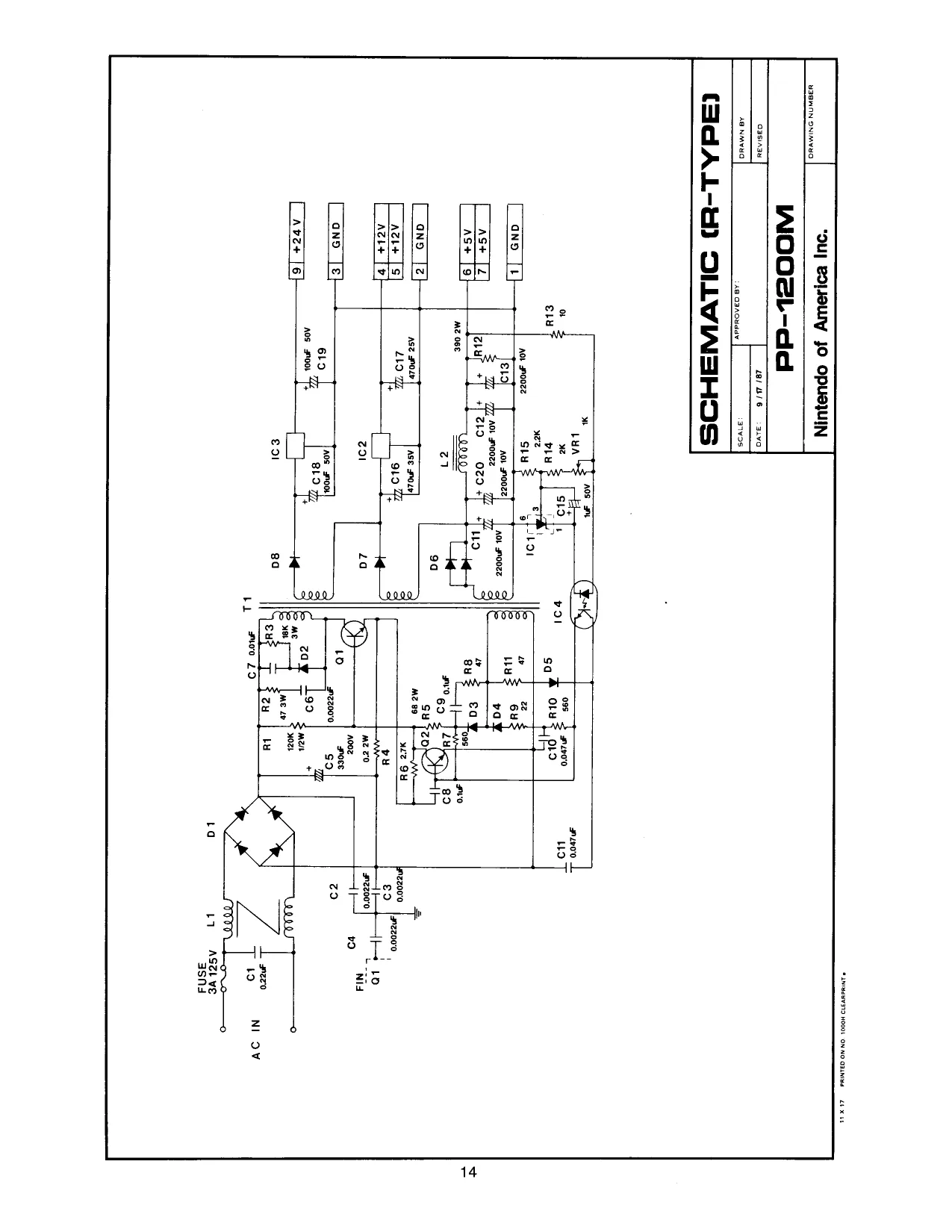
This page is a drawing, shown as the original scan.
IX. Reorder Parts List
Body Parts — Front View (Fig. 9)
ITEM PART NO.
1 RTPU-01-01 2 MGSU-01-49 3 MGSU-01-56 4 TKGU-01-29 5 TKGU-01-29-01 6 TKGU-01-29-02 7 RTPU-01-24 8 TKGU-01-48 9 TPPU-01-52 10 TPPU-01-50 1 TPPU-01-51 12 TKGU-20-00 13 TKGU-20-01 14 TPPU-01-68 15 MGSU-01-67 16 MGSA-01-23 17 RTPU-23-60 18 TKGU-01-31 19 TMAU-14-17 20 TMAU-14-18 21 TMAU-34-19 22 TMAU-14-12 23 TMAU-11-27 24 RTPU-01-32 25 RTPU-01-11 26 TKGU-01-33 27 TMAU-11-20 28 MDSA-01-71 29 TMAU-14-11 30 RTPU-11-23 DESCRIPTION
Body (Black) Speaker Grill Top Trim Fluorescent Lamp Ass’y Fluorescent Lamp Lamp Starter (Glow Lamp) Name Plate Plexi with Overlay Control Panel Retainer Monitor Support Bar Monitor Mounting Brkt Left Monitor Mounting Brkt Right Video Monitor (20-5F) (Standard Scan) Video Picture Tube Blind Cardboard (Smail) Blind Cardboard (Large) Front Screen (Glass) Operation Panel Ass’y Draw Latch Service Door ADD-S2 Coin Selector Coin Switch Front Door Lock Cash Box CS Frame 120 W Ass’y 12V Game Counter Service Switch CS Plate 120W (Only) T Molding (Black) Cash Door Side Decal (R-Type)
Yep Uf ee, \
IX. Reorder Parts List, Continued
Body Parts — Rear View (Fig. 10)
ITEM
CONATDAWN= PART NO.
MGSA-01-01-05 TKGU-01-03 TKGU-01-03-01 TKGU-01-05 RTPU-21-00 RTPU-01-01-11 MDSU-01-01-12 MDSU-01-01-13 MDSU-23-35 TPPU-01-01-14 CHPU-01-01-15 TKGU-01-08 TKGU-01-10 TKGU-01-65 TKGU-11-08 TKGU-01-30 RTPU-01-01-10 MDSU-08-00 CHPU-08-01 TKGU-01-07 RTPU-11-05 TPPU-11-25 TKGU-11-17 RTPU-23-61 MGSA-01-67 TPPU-01-68 TKGU-20-00 TKGU-20-01 TKGU-10-43 DESCRIPTION
Back Door Back Door Lock (Key #6510) Back Door Key Only (Key #6510) Cam A-lype (Back Door Lock) P.C. Board Ass’y FCC Shield Cover 062 44P FCC PC.B. Ass’'y 062 36P FCC P.C.B. Ass’y Snap In Fastener FCC Sponge (Black) Shield Cover Label Power Cord 5M Strain Relief Bushing Strain Relief Bushing Plate Fuse 5A 125V Caster Shield Cage Power Supply PP-1200 M Power Transformer PT1021A or B Back Door Lock Stopper Plate Back Door Label FCC Label Monitor Adjustment Label Operation Manual (R-Type) Blind Cardboard (Large) Blind Cardboard (Small) Video Monitor (20-EZV) (Standard Scan) Video Picture Tube Speaker 16 CM 8 OHM
Fig. 10
Operation Panel Assembly (Fig. 11) ITEM PART NO. DESCRIPTION
| 1 | MDST-14-12 | 8 Way Control Lever Assembly |
| 2 | TKGU-23-21 | Switch Collar |
| 3 | TNX-23-18 | 8 Way Guide Plate |
| 4 | TKGU-23-17 | Switch Spacer |
| 5 | TKGU-23-16 | Bearing Brkt |
| 6 | TKGU-23-20 | Spring Stopper |
| 7 | TKGU-23-22 | Lever Spring |
| 8 | TKGU-23-23 | E-Ring |
| 9 | TKGU-23-13 | Micro Switch |
| 10 | TMAU-12-15 | Lever Plate |
| 1 | TMAU-12-14 | Control Knob Plate |
| 12 | TMAU-12-16 | Control Knob Collar 8L |
| 13 | TMAU-11-18 | Knob with Shaft 80.5L |
| 14 | RTPU-01-22 | Operation Panel Base |
| 15 | TKGU-23-12 | Switch Button Bracket |
| 16 | TMAU-34-18 | Micro Switch VL 12L (Straight) |
| 17 | MDSU-12-17 | Black Sponge, 2 x 10 x 580L |
| 18 | TKGU-23-26 | Nut Plate |
| 19 | TKGU-23-34 | Pal Nut M16 |
| 20 | MDST-12-21 | Button Assembly (Black) |
| 21 | MDST-12-17 | Button Assembly (Crimson) |
| 22 | TMAK-11-19 | Operation Panel Fastener |
| 23 | TMAU-12-18 | Collar — 34 x 28 x 7H |
| 24 | MDST-12-24 | Button Assembly (Light Blue) |
| 25 | MDST-12-27 | Button Assembly (Green) |
VS. UniSystem Operation Panel Assembly Parts (Upright)
(Fig. 11)
Operation Panel Assembly
Wiring Harnesses
PART NO.
RTPU-41-11
RTPU-41-13
MGSU-41-14
RTPU-42-11
TPPU-93-07
TPPU-93-02
TMAU-41-13
TMAU-41-14
TMAU-41-12
TKGU-13-17 DESCRIPTION
56P FCC Harness
UP-072R-44P Edge Harness
UP-072-36P Edge Harness
15P Switch Harness
6P-600 Video Harness
2P-400 Audio Harness
48-800 Service Switch Harness
4P-600 Coin Sw.Harness
3P-500 Counter Harness
2P-860 Speaker Harness
M72 A-C PC Board
ITEM
CHPU-22-42 CHPU-22-44 MDST-21-28 MDST-21-27 RTPU-22-01 RTPU-22-02 CHPU-21-43 CHPU-21-29 MDST-21-23 CHPU-21-27 CHPU-22-08 MDST-21-18 RTPU-22-03 RTPU-22-04 MDST-21-21 MDST-21-20 CHPU-21-42 RTPU-22-05 CHPU-21-35 RTPU-22-06 RTPU-22-07 RTPU-22-00 RTPU-22-09 RTPU-22-10 CHPU-21-11 RTPU-22-11 RTPU-22-12 RTPU-22-13 RTPU-22-14 RTPU-22-15 RTPU-22-16 RTPU-22-17 RTPU-22-18 RTPU-22-19 RTPU-22-20 RTPU-22-21 RTPU-22-22 RTPU-22-23 RTPU-22-24 RTPU-22-25 RTPU-22-26 RTPU-22-27 RTPU-22-28 RTPU-22-29 CHPU-24-27 MDST-32-61 PART NO.
74LS174, IC1 74LS244, IC4-8, 1C16-17, 1C31, 1C42, 1C72 74LS373, IC13, IC33, IC44 7ALS245, 1C14-15, 1C18, IC34, 1C41, IC46 74ALS374, IC25-28 74ALS08, IC29, IC40 74LS374, IC30 74LS08, IC47 74LS138, IC51 74L02, IC52 TALS86, IC57 74804, IC58 74ALS00, IC59 74ALS74, IC60 74LS74, 1C61, IC69 74LS32, IC63 74LS367, IC64 74LS38, IC67 74LS139. IC68 748158, |C77 TMM2016BP-10, IC21-22 TMM2018D-55, IC23-24 TMM2018D-35, IC36-39 uPD43256C-10L, 1C70-71 D780C-1/Z80A, IC53 M51202TL, IC5S uPD70116C-8, IC56 uPD71011C, IC65 uPD71088C, IC73 uPD71059C, IC74 NuJM 064D, 1C102 YM-3014, IC103 YM-2151, 1C104 PAL16L8ACN/TIB PAL 16L8-25CN, IC11 PAL16L8ACN/TIB PAL 16L8-25CN, IC19 TBP24S10, IC66 TBP24S10, IC75 KNA71H010 (No. 15), IC2 KNA72H010 (No. 14), IC9 KNA72H009 (No. 13), IC10 KNA70H016 (No. 12), IC35 KNA65005-17, IC62 KNA70H015 (No. 11), IC76 KNA91H014, IC79 470 ohm 1/4w. R1-4, R9-10, R20 220 ohm 1/4w. RS DESCRIPTION
RAM
Comparator
PAL PAL PROM PROM Custom Custom Custom Custom Custom
Custom Carbon Carbon
ITEM
MDST-21-48 MDST-21-44 TKG-56-46 MDST-21-49 MGSP-08-16 RTPU-22-30 RTPU-22-31 RTPU-22-32 RTPU-22-33 RTPU-22-34 RTPU-22-35 MDST-21-67 MDST-21-72 MDST-21-71 RTPU-22-36 TUB-08-21 RTPU-22-37 TKG-08-27 RTPU-22-38 RTPU-22-39 TMAU-21-90 MDST-21-46 RTPU-22-40 RTPU-22-41 RTPU-22-42 MON-09-55 TMAU-21-98 MDST-21-65 RTPU-22-43 RTPU-22-24 TPP-08-11 RTPU-22-45 CHPU-21-50 RTPU-22-46 RTPU-22-47 RTPU-22-48 TMAU-21-104 MDST-21-82 CHPU-21-58 RTPU-22-49 RTPU-22-50 RTPU-22-51 RTOU-22-52 PART NO.
4.7k ohm 1/4w, R6-7, R19, R102-194 1k ohm 1/4w R8, R13-14, R101 22k ohm 1/4w, R11 10k ohm 1/4w, R12, R15 18k 1/4w, R20-22 1HR-8-472JA, RA1-2, RA12 RGLD8M472J221J, RA3-8 1HR-8-103JA, RAQ 1HR-8-102JA, RA10-11 RGSD10L471G, RA13-15 VZ103KSL2-50k ohm, VR1 0.1 mfd 12v, C1-22, C25, C27, C31-96, C114, C116 47 mfd 16v, C23, C26, C105 10 mfd 16v, C24 390 pfd 50v, C28, C97 2200 mfd 16v, C101-102 .15 mfd 50v, C103 470 mfd 25v, C104 .01 mfd 50v, C106 -001 mfd 50v, C107 1 mfd 25v, C108 2.2k ohm 1/4w, C109 6800 pfd 50v, C110 1200 ofd 50v, C111 3300 pfd 50v, C112 100 mfd 25v, C113 10 mfd 25v, C115 220 pfd 50v, IC47 Pins 7-8 DSS310-55B-101M, LC1-4 185277B, D1-2 181588, D3-4 28C2120, TR1-2 2801815, TR3 KSD-08, SW1-2 3.58 mhz, X1 32 mhz, X2 20-Pin Socket, 1C11, IC19 40-Pin Socket, IC53, IC56 16-Pin Socket, IC66, IC75 XG3A-6014, CN1-2 XC5E-5021, CN3 XC5E-6421/XC2E-6411, CN4 B3PS-VH, CNS DESCRIPTION
Carbon Carbon Carbon
R-Network R-Network R-Network R-Network R-Network Variable Resistor Ceramic Electrolytic Electrolytic Ceramic Electrolytic Polyester Electrolytic Polyester Polyester Electrolytic Carbon Resistor Polyester Polyester Polyester Electrolytic Tantalum Ceramic EMI Filter Diode Diode Transistor Transistor Dip Switch Xtal Xtal Socket Socket Socket Connector Connector Connector Base Post
M72 B-D PC Board
ITEM
CHPU-21-27 CHPU-22-08 CHPU-22-43 RTPU-23-01 MDST-21-21 MDST-21-24 CHPU-22-34 MDST-21-27 CHPU-22-42 CHPU-22-45
MDST-21-23 CHPU-21-43 CHPU-22-44 MDST-21-20 CHPU-22-46 MDST-21-19 CHPU-21-42 RTPU-23-02 RTPU-23-03 RTPU-23-19 RTPU-23-04 RPU-23-05 RTPU-23-06 RTPU-23-07 RTPU-23-08 RTPU-23-09 RTPU-23-10 RTPU-23-11 MGSP-08-16 RTPU-23-12 RTPU-23-13 MDST-21-67 RTPU-23-14 RTPU-23-15 RTPU-23-16 RTPU-23-17 RTPU-23-18 PART NO.
74LS02, 1C1 74LS86, IC2, C50, IC57, ICB0-81, IC84-85 74L$1875, IC4, IC7, IC60, IC6S 74LS166, IC5-6, IC13-14 74LS74, IC10-11, C41, 1C48, IC83 74LS157, IC12, IC15, IC61-64, IC71-74 74LS20, IC16-17 74LS00, IC18, IC28 74LS174, IC19, IC29, 131, IC38, C70, IC75 74L$273, IC30, 1032, 1C37, C39, 1C42, 1C47, 1C58-59, IC66-67 74L8138, IC40, IC49 74LS374, IC43, 1C46, 1IC53-54 74LS244, 1044-45, IC53, IC55 74LS32, IC51, IC56 74LS283, IC68-69, IC76-79, IC86-87 74LS10, IC82 74LS367, IC88 uPD4364CX-10L, 1C33-36 KNA604201 (No. 6), IC3, IC8 KNA91H014 27256, IC20 27256, C21 27256. 1C22 27256, IC23 27256, IC24 27256, IC25 27256, IC26 27256, IC27 18k ohm 1/4w, R1-4 RGSD10L471G, RA1-3 390 pfd 50v, 1-2 0.1 mfd 12v, C3-81 100 pfd 50v, C93 32-Pin Socket, IC20-27 XG3A-6014, CN1-2 IMSA-9202-H, J2-5 IMSA-9202B-1.3, J2-5 DESCRIPTION
RAM Custom Custom EPROM EPROM EPROM EPROM EPROM EPROM EPROM EPROM Resistor R-Network Ceramic Ceramic Ceramic Socket Connector Short Pin Short Base
M72 ROM-C PC Board ITEM PART NO. DESCRIPTION
| MDST-21-27 | 74LS245, 1A, 2A | TTL |
| RTPU-21-01 | uPD 4364CX-10L, 1F, 3F | RAM |
| RTPU-21-02 | 27512, 1B | EPROM |
| RTPU-21-03 | 27512, 1C | EPROM |
| RTPU-21-04 | 27512, 1H | EPROM |
| RTPU-21-05 | 27512, 1K | EPROM |
| RTPU-21-06 | 27512, 3B | EPROM |
| RTPU-21-07 | 27512, 3C | EPROM |
| RTPU-21-08 | 27512, 3H | EPROM |
| RTPU-21-09 | 27512, 3K | EPROM |
| RTPU-21-10 | 27256, 1J | EPROM |
| RTPU-21-11 | 27256, 1L | EPROM |
| RTPU-21-12 | 27256, 3d | EPROM |
| RTPU-21-13 | 27256, 3L | EPROM |
| RTPU-21-14 | PAL 16L8ACN, 7N | PAL |
| RTPU-21-15 | 1HR-8-103JA | R-Network |
| MDST-21-67 | 0.1 mfd 12v, C1-21 | Ceramic |
| RTPU-21-16 | 32 Pin Socket, 1B-L, 3B-L | Socket |
| RTPU-21-17 | 20 Pin Socket, 3A | Socket |
| RTPU-21-18 | XC5B-5021, CN3 | Connector |
| RTPU-21-19 | XC5B-6421/XC2B-6411, CN4 | Connector |
| RTPU-21-20 | IMSA-9202H, J1-2 | Short Pin |
| RTPU-21-21 | IMSA-9202B-1.3, J1-2 | Short Base |
iat
PP-1200M Power Supply
ITEM
RTPU-08-01 RTPU-08-02 RTPU-08-03 MDST-32-17 MDST-32-16 RTPU-08-04 TKG-08-15 MDST-32-18 RTPU-08-05 RTPU-08-06 RTPU-08-07 RTPU-08-08 RTPU-08-09 RTPU-08-10 RTPU-08-11 RTPU-08-12 MDST-32-37 MDST-32-35 MDST-32-31 RTPU-08-13 MDST-32-36 RTPU-08-14 RTPU-08-15 RTPU-08-16 RTPU-08-17 RTPU-08-18 RTPU-08-19 RTPU-08-20 RTPU-08-21 RTPU-08-22 RTPU-08-23 RTPU-08-24 MDST-32-43 RTPU-08-25 PCHU-21-98 MDST-32-59 RTPU-08-26 CHPU-21-70 TPP-08-23 CHPU-24-28 MDSU-08-28 RTPU-08-26 RTPU-08-27 RTPU-08-28 RTPU-08-29 RTPU-08-30 PART NO.
2SC3317, Q1 28C2235, Q2 KBL-02, D1 ERB 44-04, D2 ERB 44-02, D8 1S592, D3 181588, D4-5 ESAC82-004, D6 ERB81-004, D7 1R9431, 1C1 TA7801 ZAP, IC2 TA78024AP, IC3 PC817, IC4 PLA1021A, L1 Coil, L2 2200 pfd 125v, C2-4 2200 pfd 400v, C6 .01 mfd 400v, C7 -1 mfd 50v, C8-9 .047 mfd 50v, C10-11 .22 mfd 125v, C1 330 mfd 200v, C5 2200 mfd 10v, C12, C20 2200 mfd 10v, C13, C14 1 mfd 50v, C15 470 mfd 35v, C16 470 mfd 25v, C17 100 mfd 50v, C18-19 18k ohm 3w, R3 68 ohm 2w, R5 390 ohm 2w, R12 47 ohm 3w, R2 -2 ohm 2w, R4 120k ohm 1/2w, R41 2.2k ohm 1/4w, R15 560 ohm 1/4w, R7, R10 47 ohm 1/4w, R8, R11 10 ohm 1/4w, R13 22 ohm 1/4w, RO 2K ohm 1/4w, R14 2.7k ohm 1/4w, R6- 1k ohm Variable Resistor, VR1 Transformer 68-0435, T Fuse, 3 amp, F1 3-Pin Power Harness (in) 9-Pin Power Harness (out) DESCRIPTION
Transistor Transistor Diode Bridge Fast Recovery Diode Fast Recovery Diode Diode Diode Schottky Diode Schottky Diode Shunt Regulator Regulator Regulator Photo Coupler Coil Coil Ceramic Polyester Polyester Polyester Polyester Metallized Polyester Electrolytic Electrolytic Electrolytic Electrolytic Electrolytic Electrolytic Electrolytic Metal Film Metal Film Metal Film Metal Film Cement Carbon Carbon Carbon Carbon Carbon Carbon Carbon Carbon
XI. Diagnostic Test
To start a diagnostic test, turn the game off and set Dip Switch Number 2, position 8, to ON, then turn the game back on.
The RAM and ROM will automatically be tested upon Power Up. The screen should show “RAM OK” and “ROM OK”. If the RAMs are faulty, “RAM NG” and a number (1-6) will be shown. The number will correspond to one of the following:
Work RAM (byte check) Work RAM (word check) V-RAM A (word check) V-RAM B (word check) Sound L (byte check) OOOOH to 7FFFH Sound H (byte check) 8000H to FFFFH DARWN>
If the ROMs are defective, “ROM NG" will be shown.
To bring up test menu, press the 1-Player and 2-Player buttons simultaneously. The following test menu will be shown:
vO Sound Character Color Cross Hatch
Move the Joystick up or down to select test. Press the Fire button to start each test, and press the 1-Player and 2-Player buttons simultaneously to terminate the test and return to the test menu. The five tests are as follows:
- VO Port Test
Tests Joystick, buttons, coin acceptors and displays dip switch settings. Shown on the screen as follows:
8765432187654321 In Port 1 o0000000000000000 In Port 2 o0000000000000000 Dip Sw 0000000000000000 (0 - Off, 1 - On)
- Sound Test
Screen will show number (1-65) and corresponding sound will be heard.
- Character Test
Four ships will be displayed as shown below:
- Color Test
Move the joystick down to advance the test. The following will be shown:
Entire screen will show blue, then red, magenta, green, cyanic, yellow, white and the following color pattern:
< < wl olZ/3)z/3/e 35\G/H) a) <|S)= Z| 21S/ 2/81 Z)E =|° aa BLACK
- Cross Hatch Pattern
A 16-line cross hatch pattern will be shown with 2-dot wide white lines.
Adjustment of Video Monitor
Video Monitor + Type XM-2001N
CHASSIS LAYOUT
crt Pwe
[Je oor
swaoz [5 E a voronemtmnon opt 0 ne one Ea
Coes me ic am sun diBar Af pee HORIZONT OUTPUT O60! J; ‘SPARE FUSE. ba ea oe ue = fe soon mur ver Ow
DY PWwB “ o
CONTROL PWB “ 01 1 Powen
- CENTER pg og
Rass SiS BIG BRIGHT V-HOLD, H-HOLD sw702 oESaUGSNG-sw
ering LETHAL quantities of
been observed. energy. The Video Monitor contains HIGH VOLTAGE capable of deliv- TO AVOID DANGER TO LIFE, don't attempt to service the chassis until all precautions necessary for working on HIGH VOLTAGE equipment have
f 1 T 2 —T 3 4 TT 5 TT 6 TT 7 8 T 9 T 10 " T [Y51 Type] XM-2001N SCHEMATIC DIAGRAM
©1984 Nintendo of America Inc. XM-200IN KMS
(Pwarnissra) A
RED ouTeUT deor
Ree [i *
gaa | 728218 sh SPEAKER
oer 2scieisy
tye]
‘SOUND IN
ono lerrar ZY SE
1701 W=IKOIB7EE g POWER REGULATOR
This page reads as a drawing: its text was drawn rather than typeset, and comes out in fragments. See the original scan.
This page reads as a drawing: its text was drawn rather than typeset, and comes out in fragments. See the original scan.
This page reads as a drawing: its text was drawn rather than typeset, and comes out in fragments. See the original scan.
This page reads as a drawing: its text was drawn rather than typeset, and comes out in fragments. See the original scan.
A Kelle bs
He
e
2A Tee
SiS * 10K
rar NANAO nanao conPoraTion M72-ROM-C rr
o raaarere
SS
This page reads as a drawing: its text was drawn rather than typeset, and comes out in fragments. See the original scan.
| THe x01-0 2 « ; at 2 | * | »
;
on wm
cB co Jr cots «
on ; 4: 35%, 14)
aR. |
ree Wr a [ 1d a)
ws 1. ve
FR wD
{S138 ay ——_____4 4 Ag ———___Sq iow ————e la 7
ES rey HA | AT + VR
lemme NANAO CORPORATION TH 1 = j : _NANAO suo conronaren 1" 72-B-D 6
age ast ie
bn S28 & FRR eo ee Be
b ig
r : le Ges gest re soaked rang TRA
ROPE PERE
slabs kts bala
0 Nee epou Nee |
|<} vo 1 ere. a] Is
bls
aaso34201 ERSLESSEREE
B
fe !
EeR
gs Es a fa fo as
feof pols Be
F
‘wafer ua BE FPP. F
ro Co
NANAO wanao conponanion
[ms 7 949444 F
ie a4
RK. 64x-SRAM x2
> ZBeegaeesse ai a a ew oe crs) eos B00 Bias azas Beas 29a acct
Sef & seeing ~ giby foley bls RE ba ok
- CRESS Re | s Tl C Ebb bspls bee Ebbets Bee wA6034201 | - a at ] ra ae) Uy
eee seue 0%. 1 00- Z1Dae 100: ane ans
cous ozs conta _.. coca ; BITaA
aire Biri ; _ BIT 04 RI
TJ esse roverie
co. 38 col 28 coe co. 08 BIT 38 Bir 28 airie BiT 08 GREEN cH?
pA2
) aosotoverss
e1 xe 3A CALE EWE NZ TO
PAI .s@ ac yeS—e iL ce 7A . ca RoSOIOLATIG
a8 a? a6 aS Aa PERSE KNASTHOT4 ULL LLL UL
a !
\sxs7 Dont, 82208 “h = Boe nm a “ :
= FLAT #
NANAO nano conronanon
Z 28 3 — $013 220 a 4 eracud 8 TORO. 2B prose Bor hen be JS 22
IIA rs ONS 28 = re [2 NGA
rn or ——otisn Ne 3 i Shir, a 6 41 [ie uh in ri [iS £854 2
a] ey he Zaps Ps yh ay " Heat tt kr i
twR=B 1020 oy 3 isa, 72 paso AR, HED eS af 38 Mm -SOEN “CNS 214
ison
feo is omer -08 08
O38 NB 108 1 OK
This page reads as a drawing: its text was drawn rather than typeset, and comes out in fragments. See the original scan.
veo itr T] ¥5 [BT Trt s : : ita [5 et Mor = = = i = = a :
Ty} weot[ TH} ero Bl vb | Ho ses) we iq
a ei gt ‘
evo
OSZIOTS Labs
i el
= 855286 tives w9sz t i
ex
| NANAO tanao Conronarion @
This page reads as a drawing: its text was drawn rather than typeset, and comes out in fragments. See the original scan.
This page reads as a drawing: its text was drawn rather than typeset, and comes out in fragments. See the original scan.
This page reads as a drawing: its text was drawn rather than typeset, and comes out in fragments. See the original scan.
This page reads as a drawing: its text was drawn rather than typeset, and comes out in fragments. See the original scan.
fs |e
a)
we we D7 we D5. De SES RSIS RRR
0.2 4} 2) WA72HOTO (10
Do es
vi 7
ia aL a pane sa a io wo —__0
i 4
i tem, Ss é eis REO [2-3 ERT as ext
CANSOP "1 EKO
FER 16M
vio
ae en a
2 2 | 4 L 5 z a | ° » ! 1
ac Se vo a ie og wo cauce 2 x) fs r 06 on. 1 af Ts 16 O15 col n ye 1s] ORS co a he 81S oxo 2 1a] ov f ra Dos au si 16] 4° fis ie 3 rox J fs a 2808 m3 s] fo 3 13 Foso2 a ihe O02 FAT H fe a 2 far Ot, 0:01 fox) s aby 1
| ROA CO: aa | ‘DAO ‘ROA 10- al | 10 |
ab hh ub, fo de H 18 F
| caro | a | a |
de ot, a 3 | 2. | = res? 138
| nA08 | . | fare | |
| Be | Teseoi80 | Le | ups | meare-36 |
FA06 = mae aa05 aa,
| mana | 4 | fais | & |
paos maa i
| Face | a | rare | |
| RAT | 7 | ran | Zh, |
| faa | a | ato | a |
AS3I6 fis coat Rafah du ub 2617
| it ee | aa 3 | E16 |
r Be Ven ea F ae a os 19) an fa 1 es Feeas. i 2e03 O83 se} je x 0813 ncece un cece ware 2] {6 m 312 FOB a 2601 Ren 4 105, 0611 0600 20 ect B10 ai fe 4 2210 a t-————2lone
| ceo | 8 | set | 4 |
2 iat Py oR 36 ey cs rave
| fm | eon | ae | Ly | mecoin-25 |
fece fre {ee F805 #15 —*
| maoe | fea | te |
| RBO3 | RBIS | “4 |
Feoe raz
| FeO! | Ren | Lay |
| Fe00 | 010 | Bho |
sot so
| PK {Po2 | KO (RK A. | REF |
a 58
aa NANAO anso conporanion 5 SE ES
This page reads as a drawing: its text was drawn rather than typeset, and comes out in fragments. See the original scan.