Fhoenix
Phoenix (Amstar, set 1) (Amstar, 1980) · Document · 27 pages · 23 sections · original scan
SERVICE INSTRUCTION
PLAYER 1 SIDE
Firing Butto
Barrier Button
Coin Slot
Cash Box
PLAYER 2' SIDE
fontrol Lever Main Fuse —_——e
Power Switch
Eifing Butten™
Grounding Termi
Barrier Buttort Terminal termina
SPECIFICATIONS:
For protection of the color Video Monitor used inthe machine , care must especially be taken not to give impact on this machine during its transportation and transfer.
This machine is designed for indoor installation. It should not be installed anywhere outdoors.
WHERE IT SHOULD BE INSTALLED ( INDOORS )
It should be installed on a flat surface such as floor or concrete bed etc... with adquate space taken around the machine.
It should not be installed even on a floor with a flat surface,If any vibrations are transmitted through the floor.
It should not be installed in places obstructive of emergency protection or in the neighborhoods of places where fire protection provision are located.
FIRE ALARM
SPECIFICATIONS
Place exposed to direct sun rays,high humidity and abundant dust should be avoided. It should not be placed near heating apparatuses,So far as practicable for prevention of temperature rise inside the machine.
BEFORE THE POWER SWITCH ON }
It should be checkd to see wether or not all P.C boards are properly installed,and the connectors are perfectly provided.
The groundimg terminal provided on the machine should be wired to earth without fail.
Power switch is thrown in after inserting the power supply plug into the power supply plug socket.
The case of abnormal if the power switch on !
This machine should not move normal without legal voltage.
For a short time after connecting to power,Thepicture may be temporarily distorted. This is for a specialcharacter of C.P.U. It should be reformed after pawer switch on once more.
This machine is the combination of the I.C all Transister Video Monitor and around C.P,U,so it have along life but it should be broken for a moment for use circumstances.
PLEASE ATTENTION ABOUT FOLOW THING
Do not check the solids states module with a TESTER éven if
you find our there is somethin: wrong with it.
The I.C may be destroyed by the voltage of a TESTER.
Be sure to power switch off when the solid state modure insert or out with the socket.
For a short time connecting to power , The picture may be temporarily distorted , When the temperature of the room below zero.
SAFETY CONTROL
Even if it have planned with full safety standard, It should be the case of abnormal in long time. Therefore the orner of machine or playing manager should be check the safety condition of the machine and attention for the checkin control usual.
For 1 player or 2 players 1 coin for 1 player with 3 spaceships. 2 coins 2 players.
Insert coin and press button for 1 player or 2 players.
Move the control lever and attack with fire beam to comming attack the FHOENIX ARMY “>
Avoid the attack from PHOENIX with barrier button.
For 2 players , change to one mistake each.
wwe waiting..... 20 points attacking..... 40 points (the time of consective attack will be double point) hy frying..... 200 points
egg.eee250 points lower the wing .... 100 points
- spread the wing..... 100-800 points a in (For get highscore is shooting down the the MATHER SHIP.) 9,000 points Max,
Spaceship have added one more with 3,000 points and pass over every 30,000 points. ® ( possible to change the score )
The consective attacking is only two pattern.
DIP SWITCH [LT
P.C BOARD
eeeeeeFor the adjustment of SOUND VOLUME. It will become smaller in turning it to the arrow mark.
CHANGE OF DIP SWITCH
esse ay [To Tor | [sf or [on [6 Lora ome Sa 2 7 0 EEE ETD
NOT FOR USE ET [3,000 «30,000 ||} or par] RE a ae oY
UPRIGHT KEEP OFF
MONITOR ADJUSTMEN
G| BRIGHT oO} V HOLD E v Srey H HOLD cRI Bra V POSITION H POSITION R GAIN G GAIN B GAIN
FOCUS"
The monitor is adjusted in best condition when the shipping if there is need to adjust it as follows.
H.HOLD Adjustment for keeping the picture horizontally.
¥.HOLD Adjustment for vertical height.
BRIGHT Adjustment for the place of location.
FOCUS Adjustment for color.
MEASURE FOR TROUBLE
Video game is made up of four parts for divide into electrick.
MONITOR
P.C.BOARD
CONTROLE = VIDEO GAME
POWER SWITCH
4 each parts is connected by wiring, The game machine do not move normal that if the each parts have trouble. When it have trouble checking where is wrong of the parts of wiring. Even if it check the parts is not wrong,checking to relevancy parts.
CHECK THE EACH PARTS
Prepare the TESTER for checking tne the nomber of connector and color of wiring. 4 parts and make sure
Next checking each with the way of check (2) . The checking have(a)trancefer check(b) voltage check.
A. TRANSFER CHECK Each parts and connector of game P.C board are combined with wiring and relay connector. Please checkin the folow way that the current is on to this combination or not. 1, Prepare the TESTER and put the register range.
- The testerlead put to the connector's contact and the other lead put to the terminal of parts. if the all 0€1,transfer is OK.
FHOENIZ
THE PARTS OF CONNECTING
RELAY CONNECTOR :
CONNECTOR ___
B. CHECKING OF VOLTAGR
- Measurement of AC voltage Put the Tester to AC voltage and change the range to higher than measure voltage. Put the Testerlead to the connector contact and check
the each voltage. The voltage must be same with the top of wiring and the tail of wiring.
{2) Mesurement of DCG voltage Put the DCrange of the TESTER and change the range to higher than the mesure voltage. Put the blackeLead to GND line (OV blacklead line) the other red l&ad put the place of meusure, The voltage must be same with the gop and tail.
FHOE NIX
start
y es have sa sympt | eS y main PC board peeiee ofl ie j on again is inferio
' no ino electric (1) in braun tubg I yes
es the picture £ inferi £ eae P - can't move int Hon? Tok is norma
no the golor are
t game's progge nohiter adtu-
wiring or PCB
PCB&connecto PCR
credit with S wiring o no. come up of eredit
inferior of jcredit come uj iring or Dbogrd twice no can start the| 7° A game put to earth
i normalcy of Lt
= mf inormalcy of controle leve
iC ing D On
normalcy of voice (3)
ilt or other's come up (4)
inferior of Main board
| () | fun turn round | Ro | es | inferior of |
main fuse main fuse no
| yes | normalcy of |_ RO | inferior of |
mf after chg transform line
| 7 | ; | no | no |
Mightentio dispatch wiring and monitor's fuse
moni Of Ss a operation
les inferior of
\ monitor&swW
game progress | Y®S|reformed with| 2° inferior of
| without picture | monitor adj | monitoréwiring |
no
- no es how about sub fuse b i e 2. e De
no direct voltage reach to PCB iyhout PCB yes yes
inferior of inferior of p ng.
nicroswW_ or adj
p SW of tilt ete are Stopless (3) direct voltage yes inferior of wiring
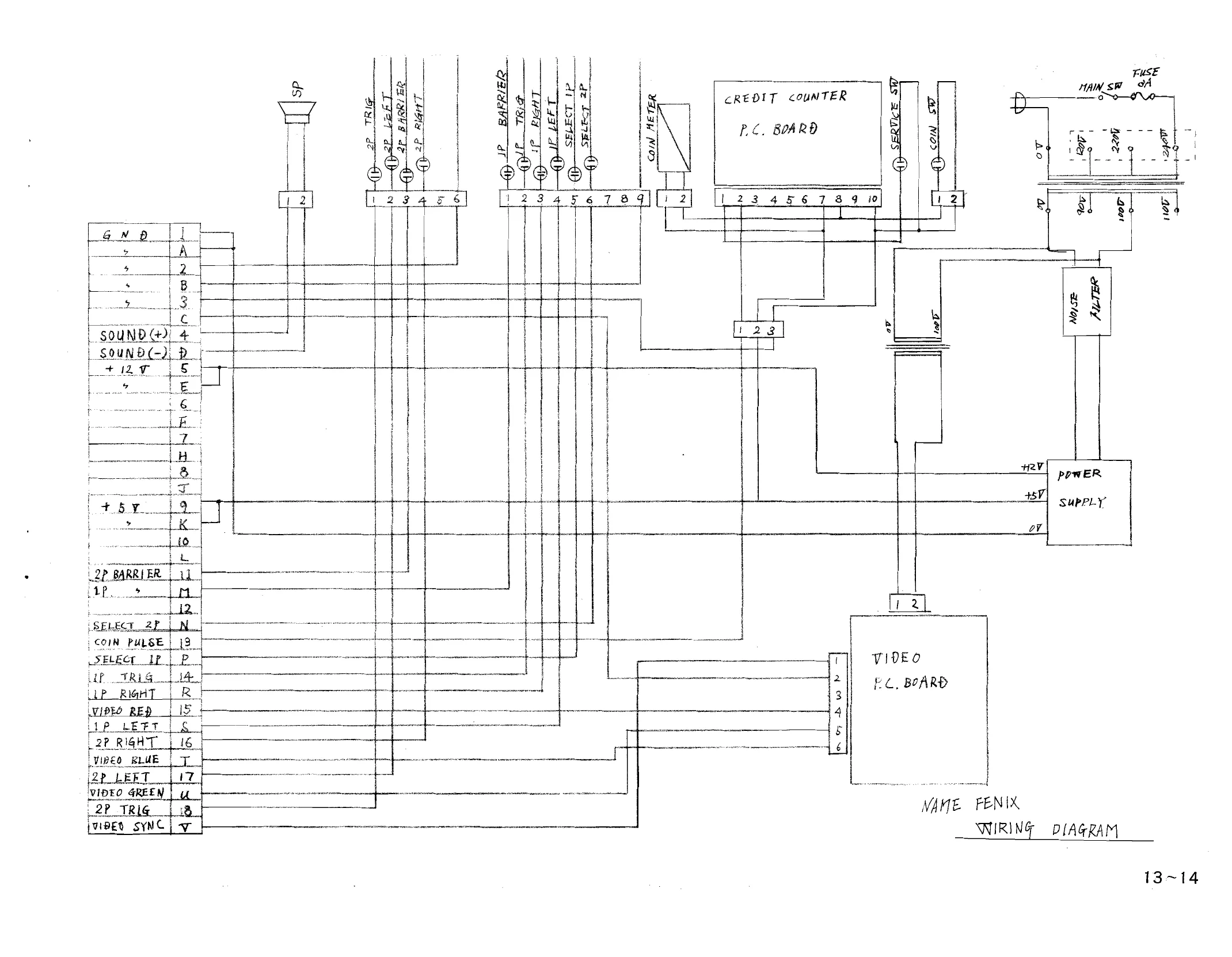
This page is a drawing, shown as the original scan.
This page carries no recoverable text. It is a drawing or a photograph. See the original scan.
ee
§ EXTERIOR ASSEMBLY
| ltem | Parts No | Description |
| 1 | sc 10110 | Table Top Glass |
| 2 | sc10111 | Video Mask |
| 3 | $C10112 | Corner Braket |
| 4 | gsc 10113 | Lock Braket |
| 5 | sc10114 | Hook |
| 6 | $C10115 | Instruction Card |
| 7 | $C 10116 | Hinge Ass'y |
| 8 | sC 10117 | Hinge Ass'y |
| 9 | sC10118 | Table Box |
| 10 | sc10119 | Bottom Box |
| li | sc10120 | Table Leg |
| 12 | sc10121 | Top Board |
| 13 | sC10122 | Coin Sticker |
This page carries no recoverable text. It is a drawing or a photograph. See the original scan.
ltem Parts No
1 §C10123
2 SC10124
3 sC 10125
4 SC10126
5 sc10127
6 SC10128
7 sc10129
8 SC10130
9 $C10131
10 $C 10132
11 8C10133
12 sc10134
13 $C 10135
14 SC 10136
15 sc 10137
16 Sc 10138
17 sc 10139
18 Sc 10140
19 sc 10141
20 8c 10142
21 sc 10143
22 sc 10144
23 sc 10145
24 $C 10146
25 $C 10147
26 8c 10148
27 $C 10149
§ CONTROL PANEL ASSEMBLY
Description
Switeh VAQ-4BR
Switch Plate
Push Button
Shaft ,
Base Bracket
MS Mounting Bracke
Insulator Type—-V
Micro Switch AH 71555
Contro! Board Bracket (8)
Washer
Plate Spring
Push Switch Bracket
Insulator Type —V
Micro Switeh VL—11L
Control Board Braeket (A)
Control Board (B)
Control Board (A)
Lever
Mask Plate
Spacer
Control Panel Control! Plate (A).
Color Ball
Control Plate (B)
Push Button Housing
Spring (A)
Push Button Red
This page carries no recoverable text. It is a drawing or a photograph. See the original scan.
ltem Parts No
i $C 10150
2 s¢10151
3 $C 10152
4 $C 10153
5 §C 10154
6 sC 10155
7 sc 10156
8 $C 10157
9 Sc 10158
10 sc 10159
uw sc 10160
12 sc 10161
13 sc 10162 14 $C 10163
15 sc 10164
16 $C 10165
17 SC 10166
18 $C 10167
19 SC 10168
20 sc 10169
21 $c 10170 22 Sc 10171
23 gc 10172
24 sc 10173
25 sc 10174
26 sc 10175
27 sc 10176
28 sc 10177
29 $C 10178
30 sc 10179
1Q VIDEO AND CABINET ASSEMBLY
Description
Support Bracket (C)
Video
Support Bracket (D)
Video Bracket
Video Circuit Board Support
Rejector for
Coin Entry Cover
Micro Switch C 5G3-3
Actuator CAA—1
Guide Plate
Coin Chute
Lock Plate
Cash Box Lock & Key
Counter ME—5
Counter Box
Pin Base
Finger Pin
Pin Guide Mounting Bracket
Pin Guide
Contact P.C, Board
Ring Terminal
Spring
Grommet NG 79—-C
Service Key No 7800
Service Lock No7800
Leck Plate
Lock Lever
Lock Lever Pin
Guide Rail
This page carries no recoverable text. It is a drawing or a photograph. See the original scan.
oo
11 PRINTED BOARD AND REGULATOR ASSEMBLY
| ltem | Parts No | Description |
| 1 | SC 10180 | Speaker |
| 2 | sC 10181 | Net |
| 3 | sc 10182 | Punching Metel |
| 4 | sc 10183 | Counter Drive P.C. Board Assy |
| 5 | sc 10184 | Print Connector |
| 6 | SC 10185 | Counter & Switch Bracket |
| 7 | SC 10186 | Push Button Switch |
| 8 | sC 10187 | C.V.- Game P.C. Board Ass’y |
| 9 | sc 10188 | AMPLEAF Connector |
| 10 | Sc 10189 | C.V.— CPV—P.C. Board Ass'y |
| 11 | sc 10190 | Molde Cord Bush |
| 12 | sc 10191 | Fuse Holder |
| 13 | sc101$2 | Mold Cord Bush Nate |
| 14 | $c10193 | Toggle Switch |
| 15 | (§C10194 | YT ransformer |
| 16 | $C10195 | AC Cord & Plug Assy |
| 17 | $C10196 | Switching Cess |
| 18 | SC 10197 | Monitor Plate |
| 19 | $cC10198 | Focus Plate |
| 20 | S$c10199 | Monitor Look Plate |
"PHOENIX" Part List FC Board
Description Serial No. Q’ ty
CPU 8085 = y Q a
P=itOM 2716 ~ nn
RAM 2114
Fuse 20M 6301
TL IG 74L800
" 74LS08
" T4514
" TALS 32
" 74L874
" 74L386
x TALS 107
" 7418125
" 7418132
" 7418136
" 748138
: 743154
. 74L8157
7 7415163
7 74LS174
a 7443244
" 7T4LS245
" 741828 3
" 748374
. 7404
" 7405
: TAOT
Ic LM555 5 8
. LM324 Qn nu et DOW wY Ww FT DN FF FY se st se SP PF PF ww FH
=
wescription
ic
C MOS”
Xx? Tal
#44 Transistor Diode ‘
Dip SW
VR
Cormector
Ribbon
mae) Socket
a
"
"
Resistor Array
"
Ceramic Capacitor
w
nw
"
"
"
Tantalum Capacitor
" :
cs
«
Hleetrolytic Capacitor Serial No.
1LM380
MN6221AA
4006
11M
234564
151588
8P
4OK—ohra
50P
50P
40P
24P
48P
16P
1K-ohm 82
1K-ohm 4R
50V 50PF
" 300PF
- — 0.001MFD
" 0.01MFD
tt 0.047MFD
"0. 4NED
16V 0.4 7MFD
7 MFD
" 2. 2MFD
: 6. Burp
- 4OKPD
16V 0 ATNMED
" {OOMED
25V 22MFD Ce a
~~ Ww NY Ww
~
"
"
“
Deseription Serial No.
Hlectrolytic Capacitor 25V = 4 7MiFD
" " 470MED
Carbon desistor RD 1/4W (3) 5%
100 ohn
270 ohm
330 ohm
470 ohm
1 K-ohm
1.2 Keohm
2.7 K-ohm
4.7 K-ohm
5-1 Keohm
10 K-ohm
20 K-ohm
33 K=onm
47 K-ohm
JOO Keohm
200 K=ohn
510 K-ohm ~ pm NY Oo
= oy > OH HD * MO HO W HY ww
oy
>
2 COIN | PLUS
+5v_») CGND [eerprr eounte pc
This page reads as a drawing: its text was drawn rather than typeset, and comes out in fragments. See the original scan.