Lunar Lander DP-136-2nd-01A
Lunar Lander (rev 2) (Atari, 1979) · Drawing Package · 1 pages · original scan
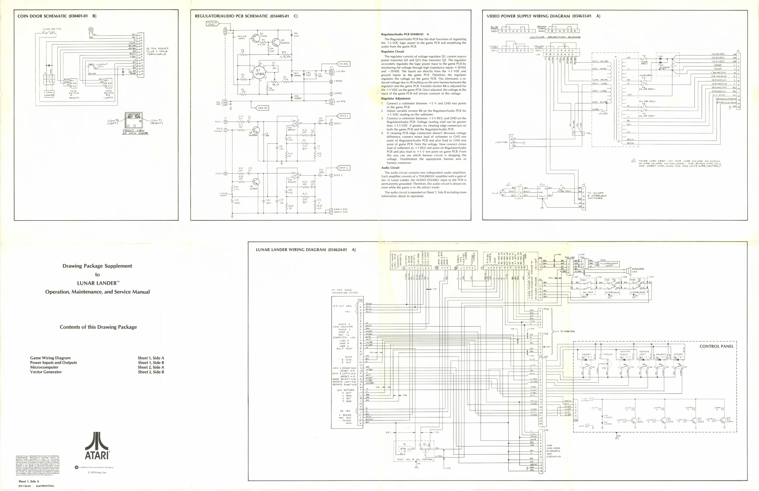
- Ss oe, COIN DOOR SCHEMATIC (030401-01_ B) REGULATORIAUDIO PCB SCHEMATIC (034485-01 C) VIDEO POWER SUPPLY WIRING DIAGRAM (034633-01 A)
Ben Bn RepltAuio PCB n48501- The Regulator PB as the al fncton of relating the 78 VDC loge power fo the game PCD on sling [
| sud om theta PC | wees | oh | AEH | ee | OE | |
| Freon | ted | sev[se7esss21] wov[se7eseszt | 7 | i | comeo | ah |
| The regulator consist of voltage regulator QI, current source: | 0° | ann | o | ———e | ae |
n Gosved) ea power transistor Q3 and Q3's bis tansstor Q2 The regulate
| om | ccrately eles the logie power input to the game PCB by | st | a | |
| ‘monitoring the voltage through high impedance inputs + SENSE | eee | ES | | | pe |
tnd SENSE, The mputs ae rectly from the +5 VOC and j a
| round inputs to the game PCR Thertore te weit | | | PTT Tt | TT | np asche | Lee | SS | Eee |
Togulats the voltage on the game PCB. Ths eliminates 8 re diced veltage de to R buildup onthe wire hamess between he tegulatr andthe game PCB, Vanebleesstor RO ade for | the +5 VBC onthe game PCB. Once adjusted the alae a the 2 tng ofthe sume PCS wl ean constant thi voltage “Regulator Adjustment
- Connect a voltmeter between +5 V and GND test pins of the game PCB
- Adjust vara resistor RB‘on the ReglatoriAuio PCB fr “£5 VDC reading onthe vlimetr
- Connect a voltmeter Between + 5 V REG and CND onthe RequatoyAudo PCB, Voltage reading shall not be greater 4 than +55 VDC. greater ty cleaning edge connects on rE both the game PCB andthe Repuatovaudio PCB.
- If cleaning PCB edge connectors doesn't decrease voltage diference,conect mins lead of vlimetr to CND test point of ReglatoiAudio PCB and pls ead to CND test point of game PCB. Note the voltage. Now connect minus ead of voltmeter to +3 REG test pent on Repulatraudio C8 and plus lead to +5 V text point on game PCB, From this you can see which haress cheat. depping the ‘eltage Troubleshoot the appropiate: hanes te 2 cen como ng, ay ie: wae, covone ba soni harness connector. Gr ten corona he pou wows sou Suaeid wine (00 She Seen wive Lens) Avo Ove mire wee ETERS, $ Stes | Sues ae 2 | Fennec
caswacyeo
cman) arn Ben EVOVeapeN-
conte] Icom at Gay S| cerca}
Audio Crit ach amplifier consists ofa TDAROOZAV ample with a gain of tenn Lunar Lander, the AUDIO DISABLE input to the PCB i
| permanently grounded. Therefore, is audio crus avays on, | Aa | nu | . | ve |
tren mle the game is nthe attract mode. | ;
| — | The audio circuits repeated on Sheet, | Side B including more | =| fo | sie ee | Tle) | oo owvore |
| “ae | ifomaton about ts peatan | aspen fl | (2) ete |
LUNAR LANDER WIRING DIAGRAM (034624-01 A) —
| Hil | ey | G12 | rrrrrictt | ae | xs |
| fi | epag | 2995.2.939 | Se23gekees | § | FoReegen |
| Drawing Package Supplement | HAS srreeverry | ee] | 3 | 3 | — |
to ARR Wes ine EEEEE Baa 3 ke gle el , LUNAR LANDER™ 88 3f. [os :
| Operation, Maintenance, and Service Manual | Setar | = | rain | Ce | eee |
| al | i= | at |
worver ono). Fe
: rae
Contents of this Drawing Package conl'eaiuren | =)
| Pia | [er | yee | perro | |
| wee | SES | oe | oo | — |
| atfder | [3S | xfer | CONTROL PANEL ! |
a pee
| Game Wiring Diagram | Sheet 1, Side A | see | [aie | At |
| Power Inputs and Outputs | Sheet 1, | B | 2 our | re pa |
| Microcomputer | Sheet 2, Side A | com + aucwrio | non | ||
| Vector Generator | Sheet 2, | ow etcern'na. | PE |
fRovare cert wo. | 1s fa = ROTATE RGHT No. 5 ;-oeee
yor [epee
ater |f
=F SY 2| |ron
© sr comrnsnon conan x = ©1979 Aa te
Sheet 1, Side A P3601 2nd PRINTING