Cruis'n USA Single Sit Down (16-40036.1-101 Jan 1996)
Cruis'n USA (v4.5) (Midway, 1994) · Manual · 89 pages · 103 sections · original scan
a) MID WA Y January 1996
16-40036.1-101
CRUIS’N USA
SINGLE SIT DOWN
FINAL MANUAL
@ CE
Operations Manual Includes:
Operations & Adjustments, Testing & Problem Diagnosis,
re) Parts Information, Reference Diagrams & Schematics
Midway Manufacturing Company, 3401 North California Avenue, Chicago, Illinois 60618
DECLARATION OF CONFORMITY
MIDWAY MANUFACTURING CO., INC.
3401 N. CALIFORNIA AVE. CHICAGO, IL 60618 U.S.A.
WE, HEREBY DECLARE UNDER SOLE RESPONSIBILITY THAT
THE MODEL: "CRUIS'N USA" 40236, 40436, 41036 (VIDEO)
TO WHICH THIS DECLARATION RELATES IS IN CONFORMITY WITH THE
FOLLOWING EUROPEAN PRODUCT SAFETY DIRECTIVES:
ELECTROMAGNETIC COMPATABILITY DIRECTIVE
(89/336/EEC AND AMENDMENTS 91/C162/08, 92/31/EEC,93/68/EEC
AS IS VERIFIED BY COMPLIANCE WITH THE FOLLOWING STANDARDS:
EN5014: 1993 EN61000-4-2: 1995 TEC 801-3: 1984 (EN61000-4-3) EN61000-4-4; 1995 EN61000-4-5: 1995
Date issued: DECEMBER 5, 1995
MANUFACTURE'S SIGNATURE
~ eee
DON HASSLER
V.P. MANUFACTURING
CRUIS’N USA
SINGLE SIT DOWN
TABLE OF CONTENTS
Section 1 - Operation Safety Notices. Set-Up Procedu Location Requirements . Installation & Inspection Servicing .. Game Featui Starting-Up Player Controls. Game Operation. Cabinet Swi 8 Control Switches -8 Menu System Operati -9 Operation. 9 Main Menu -9 Diagnostic Menu -10 Switch Test... -10 DIP Switch Test... -11 DIP Switch 2 Settings Tal -11 DIP Switch 3 Settings Table -12 CPU Test... 13 Sound Test -13 Steering Wheel Tes! Monitor Patterns Burn-in Test.. Motion Test Lamp Test. Game Audits ... Adjustments Menu . Standard Pricing Tabl Custom Pricing Utilities oo. -23 Calibrate Control 1-24 Adjust Volume 1-24 Troubleshooting Notes ......000..
Section 2 - Parts Information. Cabinet Hardware
Dash Assembly Electronics Rack . Fluorescent Lamp Assembly
Speakers Transformer Assembly Cabinet Assembly (Front View) Cabinet Assembly (Rear View). Wheel Driver Board Assembl CPU\Sound Board Assembly ... Power Supply Switch Assembly Dash Assembly .............. Pedestal w/Seat Assembly Pedestal Base Assembly... Wheel Limit Resistor Assembly NOteSscserseesnessseegresnnveccerverasinerepsetense
Section 3 - Schematics and Diagrams JAMMA Chart... Interboard Wirin: Power Wiring Diagram Cabinet Wiring Diagram . CPU/Sound Board Assembly Wheel Driver Board Assembly..
©Copyright 1994 MIDWAY Manufacturing Company
CRUIS’N USA
SINGLE SIT DOWN
SECTION
ONE
Operation
Safety Notices
The following safety instructions apply to all game operators and service personnel. Specific warnings and cautions will be found throughout this manual where they apply. We recommend th ey aut this pai je before preparing. agen for Cen - Bleavnow
AC POWER CONNECTION. Before connecting the game to the AC power source, verify that the “line voltage selection chart" jumper wires are installed correctly for the line voltage in your area. For details, refer to Section 3.
PROPERLY GROUND THE GAME. To avoid electrical shocks, do not plug in the game until it has been inspected and properly grounded. MIDWAY games should only be plugged into a grounded 3-wire outlet. Shocks will also result, if the control panel is not properly grounded! After servicing any parts on the panel, be sure that the ground wires are secure. Only then should you lock up the game.
DISCONNECT POWER DURING REPAIRS. To avoid electrical shock, disconnect the game from the AC power source before removing or repairing any part of the game.
USE THE PROPER FUSE. To avoid electrical shock, use the replacement fuse which is specified in the parts list for this game. The replacement fuse must match the original fuse in fuse type, voltage rating, and current rating.
MONITOR PRECAUTIONS. When removing or repairing the monitor, extra precautions must be taken to avoid electrical shock. High voltages may exist within the monitor circuitry and cathode ray tube (CRT) even after power has been disconnected. Do not touch internal parts of the monitor with your hands or metal objects! Always discharge the CRT by the following method: Attach one end of a large, well-insulated, 20-kv jumper to ground. Momentarily touch the free end of the grounded jumper to the anode by sliding it under the anode cap. Wait two minutes and discharge the anode again.
HANDLE FLUORESCENT TUBE AND CRT WITH CARE. if you drop a fluorescent tube or CRT and it breaks, it will implode! Shattered giass can fly eight feet or more from the implosion.
oo rts—=—C“estrr
ATTENTION!
PROPERLY ATTACH ALL CONNECTORS. Make sure that the connectors on each printed circuit board (PCB) are properly connected. If the connectors do not slip on easily, do not force them. A reversed connector may damage your game and void the warranty. All connectors are keyed to fit specific pins on each board.
Setup Procedure
Game Location Requirements
Power: Domestic 115V @ 60 Hz, 15 Amps Dimensions (assembled): Width: 30" Foreign 230V @ 50 Hz, 7 Amps Depth: 61" Japan 100V @ 50 Hz, 15 Amps Height: 67”
Temp.: 32°F to 100° F (0° C to 38° C)
Humidity: Not to exceed 95% relative. Weight: Pedestal (crated) 95 Lbs. Game (crated) 395 Lbs.
Installation And Inspection
- Remove all items from shipping containers and set them aside. Inspect the exterior of the cabinet for any signs of damage. Remove shipping cleats from the bottom of the cabinet. Remove pedestal mounting rails packed inside seat liner.
- Remove keys from the taped coin return slot. Unlock and open the coin and cash box doors. (Leg levelers and spare parts are stored in the cash box).
- Tilt or lay the cabinet down. Locate two threaded holes on the bottom of the cabinet and install one leg leveler (with its hex nut) in each hole.
- Stand cabinet upright and make certain it is in a stable position. Level the cabinet.
- Leg levelers come installed on the pedestal assembly and need only to be leveled before installing onto the cabinet assembly.
an : — - - / CABINET MOUNTING HOLES
rig | i} a | Q Zz — | 0 4 (A gy Le i ;| 8 ~ i{ fo XC
(oe CABINET BASE
MOUNTING RAILS PEDESTAL MOUNTING HOLES (j—NUTS)
- Attach mounting rails to cabinet base using four 1/4-20 hex-head bolts (see above diagram for proper placement). Do not tighten bolts completely, some movement is required in the mounting rails to align holes with pedestal assembly.
- Place pedestal assembly on mounting rails. Align the holes and carefully pull the pedestal away. Hold mounting rails in position and tighten bolts inside cabinet.
- Connect speaker wire from inside pedestal to cabinet. Attach pedestal assembly and bolt together using eight 1/4-20 tamper proof screws. Use the T27 wrench, included in the spare parts, to install these screws.
- Remove rear door of cabinet. Inspect cabinet interior for any signs of damage. Check all major assemblies to assure that they are mounted securely.
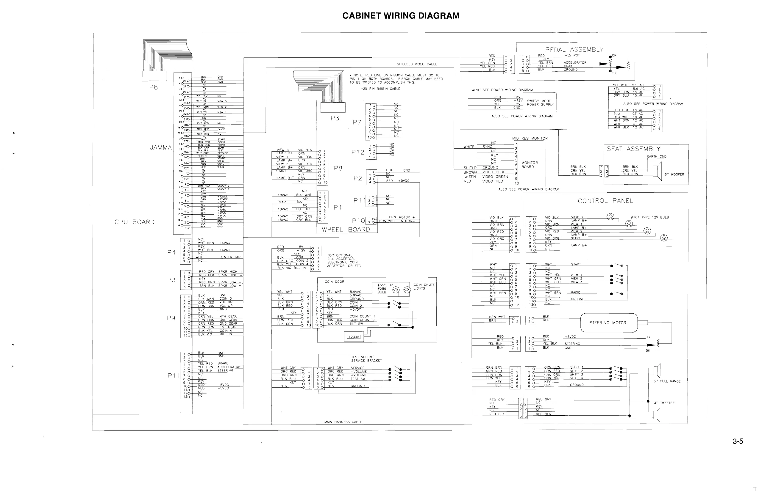
- Refer to the games Cabinet Wiring Diagram (section 3), and check to see that all cable connectors are correctly secured. DO NOT FORCE CONNECTIONS. Watch for damaged connectors and avoid making reversed connections.
- Determine the value of your line voltage with a meter. Then, check the jumper wire to the main power supply transformer. Be sure it is jumpered to correspond to your local line voltage value. If necessary, change the jumper wire to the transformer in accordance with the Jumper Chart in Section Three.
- Replace rear cabinet door and screw (lock) it securely. NOTICE: Tamper proof screws are included with the spare parts. These screws are optional and may be used to secure the rear door panel. The T20 wrench is used for the installation of these screws. Close and lock the front coin and cash box doors.
- To attach line cord, the four Phillips-head screws that mount the line cord cover plate to the rear cabinet. Match the prongs on the plug with the holes in the receptacle and push line cord securely into place. Make sure cord aligns with the indentation of plate (indentation should point toward bottom of cabinet). Remount line cord cover plate. If desired, tamper resistant screws are provided to remount cover plate.
- Connect the line cord to a grounded (3-terminal) AC wall outlet.
- Switch ON the game using the ON/OFF switch located on the upper left top of the cabinet, to verify proper operation.
SERVICING
Always turn off power to game before servicing.
Control Panel Using the T27 wrench, remove four tamper proof screws from the monitor glass retaining bracket, and set bracket aside. Remove four tamper proof screws from under the control panel. Pull control panel out and disconnect the wiring. Before reinstalling the control panel, check for proper wire connections, including ground strap.
Seat Using the T27 tamper proof wrench, remove three screws from each side of the seat mounting plate. Lift the seat/mounting plate off the pedestal assembly and place the seat on its back, on a flat surface. The six bolts under the mounting plate can now be removed to replace the seat.
Seat Slide Assembly
Using the T27 tamper proof wrench, remove three screws from each side of the seat mounting plate. Lift the seat/mounting plate off the pedestal assembly and set aside. Slide the seat assembly forward, and remove the two tamper proof torque screws from the wood panel on top of the pedestal assembly. Slide the seat back and remove the two front torque screws. Lift the wood panel out of the pedestal base and turn the unit over. Remove the four nuts holding the wood panei to the slide assembly. Place the wood panel aside and the slide assembly can be easily accessed.
Speakers
Control Panel: Two speakers are located behind the control panel. Using the T27 wrench, remove four tamper proof screws from the monitor glass retaining bracket, and set bracket aside. Remove four tamper proof screws from under the control panel. Pull control panel out and disconnect the wiring. The speakers can now be accessed from the back of the control panel assembly.
Seat: One speaker is located under the seat. Slide the seat assembly forward. Using the T27 wrench remove the two tamper proof torque screws from the wood panel on top of the pedestal assembly. Slide the seat back and remove the two front torque screws. Lift seat assembly and set aside. The speaker can now be accessed from the inside of the pedestal assembly.
Viewing Glass
Using the T27 wrench, remove four tamper proof screws holding the monitor glass retaining bracket, and set bracket aside. Carefully raise the glass from the bottom grooved edge and lift it clear of cabinet.
Monitor Bezel Using the T27 wrench, remove four tamper proof screws holding the monitor glass retaining bracket, and set bracket aside. Carefully raise the glass from the bottom edge and lift it clear of cabinet. Set it aside. The monitor bezel can now be removed by lifting it out of the grooved edge at the bottom.
1-5
. Marquee Glass Remove five 1/4” hex-head wood screws holding the plastic strip above marquee glass. Set strip aside and carefully lift glass. Store glass carefully to prevent damage.
. Fluorescent Light Assembly Remove five 1/4” hex-head wood screws holding the plastic strip above marquee glass. Set strip aside and carefully lift glass. Store glass carefully to prevent damage. Disconnect the fluorescent light assembly from its power cable. Remove the screws fastening the assembly to the cabinet and lift out the assembly.
ee
. Fluorescent Lamp Remove five 1/4” hex-head wood screws holding the plastic sirip above marquee glass. Set strip aside and carefully lift glass. Store glass carefully to prevent damage Remove the fluorescent lamp retainer brackets. Grasp the tube, give it a quarter turn and remove it from its socket. Carefully place a new tube into the socket and turn to reinstall.
. Monitor We recommend that you read the WARNINGS section thoroughly before beginning this procedure. Switch OFF power to the game. Remove the viewing glass and the monitor bezel. Completely disconnect the monitor from all of its cabling, including its chassis ground strap. Remove the six flange nuts securing the monitors mounting flanges to its mounting panel. Pull the monitor carefully from the cabinet front.
/\ caution While removing the four flange nuts, firmly support the monitor from the front of the CRT so that it will not slip.
L\ caution The monitor DOES NOT contain an_ isolation transformer in its chassis. It is mounted instead in the Power Chassis Assembly locate on the floor of the Cabinet. When servicing the monitor on a test bench, YOU MUST ISOLATE THE MONITOR FROM THE LINE VOLTAGE WITH AN ISOLATION TRANSFORMER.
1-6
Game Features
Cruis’n USA is a one player game.
Starting Up
Switch ON power to the game. A "rug" pattern appears on the CRT screen. When the
"rug" pattern ends, the screen shows a CPU Board map. Bad chips are indicated in red, good chips are in green. The software revision level is shown at the top of the screen.
Insert the desired amount of coins or tokens.
Player Controls
Start Button (Green) The start button allows the player to begin game play.
Radio Button (Orange) The radio button allows the player to turn radio sounds on and off, and change stations.
View 1-Lo Rider Button (Red) View 1 drives the car from inside.
View 2-Cruis’n Button (White) View 2 drives the car from directly behind.
View 3-Sky Hi Button (Blue) View 3 drives the car from an aerial view.
1-7
Game Operation
The Cruis'n’ USA Control Switches are located inside the coin door. These switches allow the operator to customize some features of the game.
CABINET SWITCHES
The SLAM TILT SWITCH detects any forceful vibrations against the Coin Door. This eliminates pounding for free games. It is located on the inside of the coin door.
The ON/OFF SWITCH is located on the top right side of the cabinet.
CONTROL SWITCHES
The TEST MODE SWITCH activates the games Menu System. Press the Test Mode Switch to access the Main Menu. To exit the menu system, use the Volume Down Switch and select EXIT TO GAME OVER from the Main Menu, then press the Test Mode Switch or use the Service Credit Switch.
The VOLUME UP SWITCH moves up through the menu selections or adjustment choices, and raises the sound level of the game when in game play.
The VOLUME DOWN SWITCH moves down through the menu selections or adjustment choices, and lowers the sound level of the game when in game play.
The SERVICE CREDIT SWITCH is a special feature switch that allots credit without affecting the game's bookkeeping total and is used to get out of a menu selection or return to the main menu.
-— \ 0 \
Menu System Operation
OPERATION All CRUIS'N’ USA Game Audits, Adjustments, and Diagnostics are options of the Main Menu. Each option, in turn, has its own menu, listing several choices that may be acted upon as desired.
Press the Test Mode Switch to activate the Main Menu (shown below). Game adjustments, bookkeeping, and diagnostics are all accessible from this menu.
Press the Volume Up Switch or Volume Down Switch to cycle through the menu options. Notice that the options are highlighted in sequence. Press Test Mode Switch to activate a highlighted option.
Main Test Menu
DIAGNOSTIC MENU To enter the Diagnostic Menu from the Main Menu, press the Volume Up or Down Switch to highlight the option, then press the Test Mode Switch to activate. To exit the Diagnostic Menu, press the Volume Up or Down Switch to highlight EXIT TO MAIN MENU or press the Service Credit Switch.
SWITCH TEST
Diagnostic Menu
Switch Test The Switch Test allows the operator to test the switches on the control panel and the coin door.
Select the Switch Test by pressing the Volume Up or Down Switch to highlight the option; then press Test Mode Switch to activate. Pressing a switch on the contro! panel or coin door causes the corresponding switch location on the screen to light.
Press the Test Mode Switch to return to the Diagnostic Menu.
Dip Switch Test
The DIP Switch Test allows the operator to check the location of the two 8-position DIP switches on the CPU Board. The operator can also change the setting of each position of each DIP Switch during this mode.
To enter the test, press the Volume Up or Down Switch to highlight the DIP Switch Test; then, press the Test Mode Switch to activate. The screen displays a layout of their current settings.
To change a DIP Switch setting, move the switch to the desired setting, then check the screen to verify that the switch now shows the new setting.
Press Test Mode Switch to return to the Diagnostic Menu.
DIP Switch 2 Settings Table (U97) | swi | sw2 | Sw3 | sw4 | Swe | swe | SwW7 | swe NOT USED OFF* ~ I ON MOTION OFF OFF* MOTIN ON ON _| 4 STAND UP OFF SIT DOWN ON* NOT USED OFF* | OFF* ON | ON | LINK OFF OFF* LINK ON ON NOT USED OFF] | ON
SLAVE OFF*
MASTER ON
This page reads as a drawing: its text was drawn rather than typeset, and comes out in fragments. See the original scan.
CPU Board Test The CPU Board Test (much like the Start-up Test) allows the operator to check the RAMs and ROMs.
Highlight the CPU Board Test with the Volume Up or Down Switch; then, press the Test Mode Switch to activate. When this test is activated, a "rug" pattern appears on the screen. The screen then changes to show the layout of the RAMs and ROMs on the CPU. Any chip that is shown as gray with a white outline and should turn green during the CPU Test. During the test, chips are good if they turn green; they are faulty if they turn red.
Sound Board Test The Sound Test allows listening to some of the sounds that Cruis’n’ USA is capable of producing.
To enter the test, press the Volume Up or Down Switch to highlight the Sound Board Test; then, press the Test Mode Switch to activate.
Press the Volume Up Switch to change the music selection. Press the Volume Down Switch to trigger a sound effect. Press the Test Mode Switch to exit to the Diagnostic Menu.
Steering Wheel Test
The Steering Wheel Test allows the operator to check the left to right movement of the steering wheel.
Before proceeding, make sure hands and any other objects are clear of the steering wheel. Upon entering this test, the steering wheel will automatically turn to the left to begin the testing procedure.
Highlight the Steering Wheel Test with the Volume Up or Down Switch; then, press the Test Mode Switch to activate. The steering wheel turns to the left. Press the Test Mode Switch and it turns to the right. Press Test Mode Switch again to return to the Diagnostic Menu.
Monitor Patterns The Monitor Patterns Test provides a menu for testing the monitor. Highlight the test with the Volume Up or Down Switch and activate with the Test Mode Switch. Continue pressing the Test Mode Switch to cycle through the test and automatically return to the Main Menu.
The COLOR BARS test fills the screen with several gradated colors to help with red, green and blue level adjustments. Each color should appear sharp and clear.
The RED, GREEN, and BLUE SCREEN tests fill the screen with either red, green or blue.
The CROSSHATCH PATTERNS test fills the screen with a grid and should be clear.
If any of the Monitor Pattern Tests shows a need for adjustment, use the proper white knobs on the Monitor Board.
Burn-in Test The Burn-in Test continually repeats the CPU Board Test. Press the Volume Up or Down Switch to highlight the Burn-in Test; then, press the Test Mode Switch activate. When the Burn-in Test detects an error, the test stops and displays an error message on the screen. Use this test to find intermittent CPU problems.
To exit this test, switch the game OFF then ON again.
Motion Test (Not Used)
Lamp Test
The Lamp Test allows the operator to test the lamps on the control panel.
To enter the test, press the Volume Up or Down Switch to highlight the Lamp Test; then, press the Test Mode Switch to activate.
Press the Volume Up or Down Switch to highlight lamp selections, then press the Test Mode Switch to activate that lamp.
To exit, press the Volume Up or Down Switch to highlight EXIT TO MAIN MENU; then, press Test Mode Switch to activate, or press the Service Credits Switch.
1-14
GAME AUDITS To enter Game Audits from the Main Menu, press the Volume Up or Down Switch to highlight the option; then, press the Test Mode Switch to activate. To advance to the next page of the Game Audit Table, press the Volume Up or Down Switch. Press the Test Mode Switch to exit. The Game Audits Table records the game play statistics. The left side of the table names the Audit item; the right side shows the amount of play. LEFT COIN )
| |RIGHT.COIN | ; | ag | ae | eas | 0 |
| THIRD COIN. = | ae | + . | 0 | ||
| FOURTH CON | ae | 0 |
SERVICE Ce “9
| TOTAL STARTS. | a | eee | o| |
TOTAL CONTINUES ae ere
| FREERACES — | gr | 0 |
EXPIREDRACES = 0 FREE RACE PERCENTAGE 0
POWER ON TIME SECS 0
| GAMETIMESECS | Boe | =) |
AVERAGEGAMETIMESECS ti
Page 1 of Audit Table
AUTOMATIC SELECTED MANUAL SELEOTED ;
| DEVASTATOR SELECTED | pea | en |
| ITALIA SELECTED — | ee | 0: |
JEEP SELECTED 0 ‘COPCAR SELECTED. 0
VIEWI TIME SECS 7)
VIEW2 TIME SECS 0 VIEWS" TIME SECS
Page 2 of ‘Audit Table
1-15
This page carries no recoverable text. It is a drawing or a photograph. See the original scan.
1-17
ADJUSTMENTS MENU
The Adjustments Menu option allows the owner/operator to change the Game Pricing and Game Difficulty.
The Adjustments Menu offers several options. Press the Volume Up or Down Switch to highlight an option; then, press the Test Mode Switch to activate. The activated item provides a setting choice. Press the Volume Up or Down Switch to change the current setting value. After an item has been changed a confirmation box appears. For example:
SELECT THIS PRICING? ARE YOU SURE?
YES NO
Press the Volume Up or Down Switch to YES or NO, then press the Test Mode Switch to lock in the new setting.
STANDARD PRICING. er
CUSTOM PRICING.. = ‘FREE! PLAY. : LACE AWARDS FREE GAME.
: LACE AWARDS FREE GAME START TIME BONUS SECS
LTIMESECS. = 2 ‘ATTRACT MODE SOUND Seale HIGH SCORE ENTRY eet Pe Se MIN'VOLUME LEVEL =
SPEED IN MPH OR KPH
SHOW ROADKILL
SHOW PRESIDENT ES gl SHOW GIRLS Mee HIGH SCORE DIFFICULTY a
MAX CREDITS aoe.
EXIT TO MAIN MENU ee
Game Adjustment Menu
To exit the Adjustments Menu, press the Volume Up or Down Switch to highlight EXIT TO MAIN MENU; then, press Test Mode Switch to activate, or press the Service Credits Switch.
1-18
Standard Pricing
Standard Pricing allows the operator to choose any of the "Standard" selections for the Standard Pricing Table.
Custom Pricing
Custom Pricing allows the operator to install pricing other than that of the Standard Pricing Table. Custom Pricing also allows the operator to select the amount of credits required to start a game and the amount of credits required to continue a game. This option is adjusted from the Dip Switch Settings.
Free Play
This option selects free play. The setting choices for this adjustment are: -Off (factory setting) -On
First Place Awards Free Game Awards a player a free game on 1st position. The setting choices for this adjustment are: -On (factory setting)
Start Time Bonus Secs -Maximum: 90
This determines the initial time a player is given to finish a race. The setting range is:
-Minimum: 60 -Factory Setting: 75
Checkpoint Bonus Time Secs
This awards the player a time bonus for passing a checkpoint. -Maximum: 40 -Minimum: 25 -Factory Setting: 20
Attract-Mode Sound This determines whether the game will make sounds in the attract mode. The settings for this adjustment are: -On -Off (factory setting)
High Score Entry This determines whether the game will allow High Score Entry and Display Table. The setting choices are: -On (factory setting) -Off
1-19
Min Volume Level This determines the minimum level allowed when setting the volume of the Sound Board. The setting range is: -Maximum: 30 -Minimum: 0 -Factory Setting: M1
Speed in MPH or KPH This determines speedometer setting in miles per hour or kilometers per hour. -MPH (factory setting) -KPH
Show Road Kill This determines whether the game will show road kill. The settings are: -On (factory setting) -Off
Show President This determines whether the game will show the president. The settings are: -On (factory setting) -Off
Show Girls This determines whether the game will show girls. The settings are: -On (factory setting) -Off
High Score Reset
The number of games played before an automatic reset of High Score occurs. The setting range is1000 to 25,000. -Factory Setting: 5000
Game Difficulty
This allows the operator to select the difficulty level of the game. The setting range is::
-Easiest: 0
-Hardest: 9
-Factory Setting: 5
Max Credits This determines the maximum credits allowed to begin a game. The setting range is: -Maximum: 10
-Minimum: 30
-Factory Setting: 30
Wheel Sensitivity
This controls the responsiveness of the steering wheel. The setting range is: -Maximum: 5 -Minimum: 1 Factory Setting: 5
1-20
Standard Pricing Table
| Name | Seitings Credit/Coin | Left Chute | Center Chute | Right Chute | Fourth Chute | |||
| USA1 | 1/3X25 | 25 | 25 | .25 | $1.00 |
| USA2 | 1/2X25 | 25 | 25 | .25 | $1.00 |
| USA3 | 14X25 | 25 | 25 | .25 | $1.00 |
| USA4 | 1/5X25 | 25 | 25 | .25 | $1.00 |
| USAS | 1/6X25 | 25 | 25 | 25 | $1.00 |
| USA6 | 118X25 | 25 | 25 | .25 | $1.00 |
| USA7 | 1/8X25, 1/2X100, 3/500 | .25 | 25 | 25 | $1.00 |
| USA8 | 1125, 3X25/START, 2X25 CONT | 25 | 25 | .25 | $1.00 |
| USAQ | 1/25, 2X25/START, 1/25 CONT | 25 | 25 | 25 | $1.00 |
| USA10 | 200/START, 150 CONT | 25 | 25 | 25, | $1.00 |
| USA11 | 1/6X25, 4/500 | 25 | 25 | 25 | $1.00 |
| USA12 | 1O0/START, 3X25/CONT | 25 | 25, | .25 | $1.00 |
| GERMAN1 | 1/3X1DM, 2/5DM | 1DM | 5DM | ||
| GERMAN2 | 4/1DM, 5/5DM | 1DM | 5DM | ||
| GERMAN3, | 1/2X1DM, 3/5DM | 1DM | 5DM | ||
| GERMAN4 | 2/5DM, 1/3X1DM ECA | 5DM | 1DM | 2DM | |
| GERMANS: | 3/5DM, 1/2DM, 1/2X1DM ECA | 5DM | 1DM | 2DM | |
| GERMAN6 | 1/3X1DM, 2/5DM NO BONUS | 1DM | 5DM | ||
| GERMAN7 | 1/2X1DM, 3/5DM NO BONUS | 1DM | 5DM | ||
| GERMANS | 1/1DM, 6/5DM NO BONUS | 41DM | 5DM | ||
| FRENCH1 | 4/10F, 2/20F, 4/30 | 10F | 20F | ||
| FRENCH2 | 1/10F, 2/20F, 5/40F | 10F | 20F | ||
| FRENCH3 | AMOF, 3/20F, 7/40F | 10F | 20F | ||
| FRENCH4 | 4ISF, 2/10F, 5/20F | SF | 10F | ||
| FRENCH5 | 4/5F, 3/10F, 7/20F | SF | 10F | ||
| FRENCH6 | ANMOF 2/20F, 4/30F ECA | 1F | 10F | 5F | 20F |
| FRENCH7 | AMMOF 2/20F, 5/40F ECA | 1F | 10F | SF | 20F |
| FRENCH8: | AM OF 3/20F, 7/40F ECA | 1F | 10F | SF | 20F |
| FRENCH9 | ASF 2/10F, 5/20F ECA | 1F | 10F | SF | 20F |
| FRENCH10 | 4/5F 3/10F, 7/20F ECA | 1F | 10F | SF | 20F |
| FRENCH11 | 4/3X5F, 4/50F | SF | 10F | ||
| CANADA1 | 1/2X25, 2/100 | 25 | $1.00 | ||
| CANADA2 | 1/4X25, 1/100 | 25 | $1.00 | ||
| CANADA3 | 1/4X25, 1/100, 3/2X100 | 25 | $1.00 | ||
| SWISS1 | 4/3X14F, 2/5F | 4F | SF | ||
| SWISS2 | 4/1F, SISF | 1F | SF | ||
| SWISS3 | 1/2K1F, 3/5F | AF | SF | ||
| ITALY1 | 4/500LIRE | 500 LIRE | 500 LIRE | ||
| ITALY2 | 1/2XS500LIRE | 500 LIRE | 500 LIRE | ||
| ITALY3 | 14X500LIRE | 500 LIRE | 500 LIRE | ||
| UK1 | 2/00P, 1/50P, ECA | 100P | 20P: | 50P: | 10P. |
| UK2 | 41/100P, 1/2X50P, ECA | 100P | 20P | 50P | 10P |
| UK3 | 1/3X20P, 1/50P | 20P | 50P | ||
| SPAIN1 | 1/100PESETA, 6/500PESETA | 100P | 500P | ||
| SPAIN2 | 3/2X100PESETA, 7/500PESETA | 100P | 500P | ||
| SPAIN3 | 100PESETA, 5/500PESETA | 100P | 500P | ||
| SPAIN4 | 112X100PESETA, 3/500PESETA | 100P | 500P | ||
| SPAINS | 2NO0PESETA, 10/500PESETA | 100P | 500P | ||
| SPAING | ANOOPESETA ECA | 25P. | 200P | 100P | 500P |
| AUSTRALIA1 | 1/5X20, 1/100 | .20 | $1.00 | ||
| AUSTRALIA2 | 1/10X20, 1/2X100 | .20 | $1.00 | ||
| AUSTRALIA3 | 112X100 | $1.00 | $2.00 | ||
| AUSTRALIA4 | 1/3X100 | $1.00 | $2.00 |
1-21
Custom Pricing
Coin Slot (1) Unit: Coin Slot (2) Unit: Coin Slot (3) Unit: Coin Slot (4) Unit:
Bonus Units:
Minimum Units:
Units to Start:
Select Custom Pricing:
Show Fractions:
BONUS UNITS® -
-MINIMUM UNITS
EXIT TO MAIN MENU
Coins inserted accumulate units. This adjustment specifies the number of units given for each coin in each chute (see "units/credit").
One bonus credit is awarded after this many coin units have accumulated.
No credits will be awarded until this many coin units have accumulated.
Units needed for one credit.
When set to yes custom pricing is enabled.
When set to yes, fractional credits will be seen on the credits screen.
1-22
UTILITIES
Press the Volume Up or Down Switch to highlight the Utilities option on the Main Menu; then, press the Test Mode Switch to activate.
The Utilities Menu allows the owner/operator to clear the games bookkeeping memory and to install a custom message.
EXIT TO MAIN MENU ‘ = Ufilities Menu
Press the Volume Up or Down Switch to highlight an item from the Utilities Menu; then, press the Test Mode Switch to activate. After an item has been activated, you are given the option of resetting that item or not. For example:
CLEAR CREDITS? ARE YOU SURE?
YES NO
Press the Volume Up or Down Switch to choose YES or NO, then press the Test Mode Switch to lock the choice and return to the Utilities Menu.
To exit the Utilities Menu, press the Volume Up or Down Switch to highlight EXIT TO MAIN MENU; then, press Test Mode Switch to activate selection or press the Service Credit Switch.
1-23
CALIBRATE CONTROLS
Press the Volume Up or Down Switch to highlight the Calibrate Controls option on the Main Menu; then, press the Test Mode Switch to activate.
Remove hands and feet from all controls. Set the steering wheel to the center position, then press the Test Mode Switch. Turn the steering wheel to the left-most position, then press the Test Mode Switch. Turn the steering wheel to the right-most position, then press the Test Mode Switch. Push the gas pedal to the maximum position, then press the Test Mode Switch. Push the brake pedal to the maximum position, then press the Test Mode Switch to complete the calibration and return to the Main Menu.
ADJUST VOLUME
Press the Volume Up or Down Switch to highlight the Adjust Volume option on the Main Menu; then, press the Test Mode Switch to activate.
Press the Volume Up Switch to increase, or the Volume Down Switch to decrease the sound level of the game. Press the Test Mode Switch to lock the volume level and return to the Main Menu.
1-24
Troubleshooting
PROBLEM
NO PICTURE OR DISTORTED PICTURE.
TURN GAME ON & NOTHING HAPPENS.
NO SOUND.
NO GENERAL ILLUMINATION.
PRESS START BUTTON AND NOTHING HAPPENS.
NO CREDIT GIVEN WHEN COINS ARE INSERTED.
TOO MANY CREDITS FOR NUMBER OF COINS INSERTED.
GAME STAYS IN THE TEST MODE. POSSIBLE SOLUTION
Check for faulty video board or monitor. Check for disconnected video signal cable.
Check line fuse. Check for +5VDC at pins C, D, 3, and 4 of the JAMMA Connector.
Check the speaker and speaker connection to pins L and 10 on the JAMMA Connector. Check volume control setting. Check for +12VDC at pins F and 6 on the JAMMA Connector. Check inter-board wiring on CPU Board. Check sound fuses.
Check the 1.0A., F.B. fuse located in the Power Chassis Assembly.
Check for open wires between the button and CPU Board. Check for contamination on CPU Board pins or the button switch blade contacts. Check for proper ground.
Check for contamination on coin switch contacts. Check for an open wire between Coin Switch 1 and pin 16 on the JAMMA Connector or Coin Switch 2 and pin T of the JAMMA Connector.
Check Game Pricing setting. Check for a Short between pins T & 16 on the JAMMA Connector.
Check that the Test Switch in the coin door and the Test Switch (Position 1) on DIP Switch 2 are set to Off.
1-25
1-26
CRUIS’N USA
SINGLE SIT DOWN
SECTION
TWO
Parts Information
2-1
Cabinet Hardware Cabinet Assembly A-17889.1 Lock Retainer Plate 01-7264 Upper Door Lock Cam 01-8989 Leg Leveler Plaie 01-9155 Wheel Bracket 01-9359 Wheel Bracket 01-9359 Lock Plate 01-11285 Door Bracket 01-11291 Shaft Caster 02-4404 20” Vent Hole Cover 03-7602 Leg Adjuster, 3.0” 08-7377 Door Cam Lock 20-6542-TB Caster Wheel 20-9627
Coin Door Assembiy 09-74000-33
Coin Vault Enclosure A-19504
Tamper Proof Screw Tool, T-20 20-9620 #555 Bulb, 6.3v 24-8768 Marquee 31-2005 Marquee Retainer 03-8252-5 Marquee Glass 08-7852
CRT Glass 08-7853 Peddle Assembly 20-10135 Floor Mat 23-6723 Floor Mat, Pedestal 23-6741
Cables Line Voltage Cable Assembly A-19248 Transformer Jumper Cable H-13378 GA. Jumper Cable H-15945, Fluorescent Lamp Cable H-16303 Switcher Power Cable H-17914 Control Cable H-18175 Four Speed Shift Cable H-18737 AC Power Pack Cable H-19251 Cable Bass Speaker H-19256 Main Harness Cable H-19302 Video Signal Cable H-19357-3
Dash Assembly Dash Assembly A-19271
Electronic Rack Efectronic Rack CPU Sound Board Assembly CPU Board Cover CPU Board, Mtg. Plate Power Supply Switcher Assy. Steering Wheel Driver Assy. Ribbon Cable, 20-pin Ribbon Cable, 20-pin A-19301 A-19233-40033 A-19513.2 A-19539 A-15202-1 A-18004-40033 5795-10937-06 5795-14465-60
Fluorescent Lamp Assembly Fluorescent Housing & Bracket Lamp Lock 18” Fluorescent Bulb, 15w
Manual A-15890 03-8327 24-8809
Instruction Manual 16-40036-101
Monitor Monitor, 25” 5675-14041-00 Monitor Bezel 03-9098 Monitor Cover Assembly A-19288 Monitor Support Bracket A-19501
Seat Assembly Pedestal w/Seat Assembly A-19304
Speakers Speaker, 42, Tweeter, 15w Speaker, 4Q, 6”, 25w Speaker, 4Q, 5-1/4”, 25w 5855-12924-00 5555-12929-00 5555-12856-00 Speaker Grille 01-12816
Transformer Assembly Power Pack Assembly A-19244 AC Power Pack Chassis Assy. A-19245 Transformer Jumper Cable H-13378 Gl. Jumper Cable H-15945 Cable, AC Power Pack IEC. H-19251 Line Filter, 5Amp Power Transformer Fuse, SB, 1A, 250v Fuse Holder, Panel 5102-13864-00 5610-13965-00 5731-06569-00 5733-12869-00
Cabinet Assembly
(Front View)
01-12816 SPEAKER GRILLE
A-15890 FLUORESCENT LAMP ASSEMBLY
03-9098 MONITOR BEZEL
5675-14041-00 25” MONITOR A-19271 DASH ASSEMBLY
09-74000-33 COIN DOOR ASSEMBLY A-19304 PEDESTAL w/SEAT ASSEMBLY
CASHBOX DOOR
20-10135 PEDDLE ASSEMBLY
2-4
Cabinet Assembly
(Rear View)
5642-13935-00 ON/OFF SWITCH
A-19288 MONITOR COVER ASSY.
A-19539 f MTG, PLATE-CPU BOARD
A-19513.2 CPU BOARD COVER
REAR DOOR
A-19233-40033 A-18004-40033 CPU/SOUND BD. ASSY. STEERING WHEEL DRIVER ASSEMBLY
___ 01-0714 LINE CORD COVER
A-15202-1 POWER SUPPLY __/ SWITCHER ASSY. 20-9627 CASTER WHEEL
Part Number
A-18005.1 5340-12958-CO 5340-12959-00 5311-12538-00 531 1-14067-00 5311-14068-00 5311-10948-00 5430-13598-00 5372-13323-00 5371-14070-00 5370-12602-00 5700-12047-00 5370-14069-00 5160-10262-00 5100-13945-02 5040-08986-00 5040-12298-00 5040-13417-00 5791-10862-09 5791-10862-02 5791-10862-04 5791-12461-04 5781-09437-00 $791-12461-11 5791-10850-00 §791-12461-10 5733-14113-00 5070-09045-00 5551-09822-00 5671-13732-00 5010-10428-00 5019-09362-00 5705-14076-00 5701-14092-00 4006-01003-08 4008-01003-08 4406-01128-00 4408-01128-00 03-9129 5162-08976-00 §791-10862-03 A-18005.1-Al 5010-14093-00 5010-13844-00
5010-13593-00
5010-091 34-00 5010-13594-00 5010-08931-00 §010-13372-00 5010-09998-00 5010-13596-00
5010-13364-00 5010-13371-00 5010-13365-00
5010-14065-00 5010-13366-00 P6 P7, P8 F1-F3 Ds, D6 u LEDt R112, R113. SR1-SR3
Qi Pq A-18004-40033 Wheel Driver Board Assembly
| Description | Part Number | Designator | Description |
| Wheel Driver Board Assembly | 5043-08980-00 | 81-84, B7-B9, | Capacitor, 01F,50v(+80,-20%) |
L.C. 26L831 B10-B12, B17-B19, ILC. 26L832 C8, C9, C31 ;
| Lc. 74HC14 | 5043-08996-00 | C26, C27, C29, | Capacitor, .1,F, 50v,(#20%)Ax. |
ILC. 740245 C32, C35-C37 ; ;
| 1.0. 74HC574 | 5048-12577-00 | C28 | Capacitor, .47UF, 50v, Axial |
| LC. 74HC138 | 5048-13375-00 | C10-C25 | Capacitor, 100PF, 50v,10% Ax. |
| 1.C.75160B | 5048-11031-00 | C1,C2,C39 | Capacitor, .001pF,50v, 10% Ax. |
| I.c. ADCOB48 | 5040-09343-00 | C30, C33 | Cap. Electrolytic , 10HF, 20v |
| 1.C. DACO8, D-A Converter | 5070-08919-00 | D1 | Diode, 1N4148 |
| 1.C. ULN2064B | 5075-09135-00 | D4 | Zener Diode, 10v, 1N4740A |
| Solder Socket , 24-pin, 3” | 5075-12824-00 | D7,D8 | Zener Diode, 12v, 1N4742A |
| 1.C.LM12, Power OP-AMP | 5075-14066-00 | D2,D3 | Zener Diode, 15v, 1N4744A |
| Trans. 2N3904 | A-19674 | us | Pifd. Assy. Wheel Driver |
| Bridge, 4.0A. | A-19675 | u19 | Pifd. Assy. Wheel Driver |
| E | 3731-14094-00 | 1, F2 | Fuse, SB, 4A, 5 x 20mm |
Cap., Electrolytic, 100uF, 10v Cap., Electrolytic, 100uF, 40v Cap., Electrolytic, 10,000uF Connector, 9-pin Header .156 Connector, 2-pin Header 156 Connector, 4-pin Header .156 Connector, 4-pin Header .100 Connector, 20-pin Rib. Header Connecior, 11-pin Header .100 Connector, 26-pin Rib. Header Connector, 10-pin Header .100 Fuse Holder, 5x20mm Diode, MR501 Inductor, 4.7HH LED, Red Resistor, 470Q, 1w, 5% Resistor, 4.7KQ SIP Heatsink, 4 Lead TO-3 Thermal Pad For Power AMP Mach. Screw, 6-32 x 1/2" Mach. Screw, 8-32 x 1/2” Nut, 6-32 KEPS Nut, 8-32 KEPS Nylon Spacer Transistor, 2N6427 Connector, 3-pin Header Wheel Driver Assy., Auto-Insert 5731-14468-00 F3
R23, R47, R116 Resistor, 0, 1/8w, 5% R43, R44, R48, Resistor, 100KQ, 1/8w, 5% R49, R52, R53, R56, R57, R60, R61 R30, R33, R34, Resistor, 10KQ, 1/8w, 5% R36-R39, R46, R51, RSS R59, R63-RE6, R115, R42 R26 R31, R35. R19 R67-R74 R45, R50, R54, R58, R62 R1-R16, R114 R21, R24, R27, Ritg R41 R18, R28, R32, Ris Resistor, 150K, 1/4w, 5% Resistor, 1KQ, 1/8w, 5% Resistor, 1KQ, 1/2w, 5% Resistor, 220Q, 1/8w, 5% Resistor, 2KQ, 1/4w, 5% Resistor, 33KQ, 1/8w, 5%
Resistor, 33, 1/8w, 5% Resistor, 330Q, 1/8w, 5% Resistor, 4.7KQ, 1/8w, 5%
Resistor, 75K, 1/8w, 5% Resistor, 4702, 1/8w, 5%
2-6 Fuse, SB, 3A, 5 x 22mm
A-18004-40033
Wheel Driver Board Assembly
E ant
sn] 30 _ — = am] Ga) De an) poe Wicrcm) evan tA) bzing {site
2-7
A-18005.1
Wheel Driver Assembly, Auto -Insert
A-18005.1-Al
A-19233-40033 CPU/Sound Board Assembly
Part Number Designator Description
| 5880-11056-00 | Bt | Baitery-Litium 3V |
| 5731-14468-00 | FA,F2 | Fuse SB 3A 5x20mm |
| A-19668 | Us2 | Assy. Plfd. Crusin CPU |
| A-19669 | U38 | Assy. Plfd. Crusin CPU |
| A-19670 | U43 | Assy. Plfd. Crusin CPU |
| A-16971 | U5s4 | Assy. Pifd. Crusin CPU |
| A-19672 | uid | Assy. Plfd. Crusin CPU |
| A-19673 | Uitt | Assy. Plfd. Crusin CPU |
| A-5343-40033-2, -29 | U2-U29 | E-PROM Assembly |
| A-19234 | - | CPU Sub-Assembly |
5040-13417-00 C191,C192 — Capelectro, 10,000MF, 35v
| 5370-12602-00 | 122 | ULN2064-Quad High Current |
Darlington Switch
| 5070-09054-00 | D1-04 | Diode, 1N4004 |
| 5370-13419-00 | U78, U81 | TDA2030 |
| 8370-12730-00 | U78, U80 | TLOB4 |
5340-13304-00 U35, U41, U42 2K x 8 SRAM
| 5340-13597-00 | U85, U87 | 62256, 32Kx8 BIT SRAM, 55nS |
| 5340-12558-00 | U3 | 8Kx8 CMOS SRAM, 120nS. |
| 5371-13299-00 | U61 | AS1851 |
| 5372-12901-00 | Ut30 | ADC0844-8 BIT A TO D |
Converter w/4 CH. Muitiplexer
| 5340-12958-00 | U92 | AM26LS31 - Quad Differential |
Line Drivers
| 5340-12959-00 | u91 | AM26LS32 - Quad Differential |
Line Receivers
| 5344-14130-00 | U45, U58 | IDT7204, CMOS Parallel FIFO. |
4K x 9 BIT, 20nS.
| 5434-12255-00 | 30 | Max691, Power ON Reset/ |
WATCHDO/CMOS CTL Circuit
| 5283-10551-00 | U62 | 74F00 |
| 5286-14178-00 | U55 | 74AS02 - ALS TTL Quad 2 |
Input NOR GATE
| 5280-09309-00 | U82 | 7407-TTL Hex Buffer wi High |
Voltage Output
| 5311-12538-00 | U63 | 74HC14 |
| 5281-09500-00 | U36 | 7ALS32 |
| 5281-09487-00 | u64 | 74LS74 |
| 5311-10948-00 | U34 | 74HC 138 |
| 5317-12023-00 | U88 | 74ALS138-ALS TTL 3/8 |
Decoder 5311-12043-00 5430-14290-00
5317-12208-00
5311-12287-00
5317-12211-00
$317-122 12-00
5430-13598-00
5250-13303-00 5250-13302-00 5521-13806-06 5521-13806-05 5521-13603-01 5520-13301-00 5671-13732-00 U40, U51 74HC174 U126-U128 —_74176B-Bidirectional Transceiver U44, U46, U48, 74ALS245, ALS TTL Octal U49, U98, Bus Transceiver 107, U108, U113 U33, U39, 74HC541 - HC TTL Octal Buffer USO, U93, U104, U105, U109, U112, U116, U119, U120, 121, U125 U32, U47, 74ALS541 - ALS TTL Octal U65, U66, Buffer U86, U110 U37, U53, 7A4ALS574 - ALS TTL Octal U99, U100, Flip-Flop U103, U106, U115, U118, U123 U117, U124 75180 - Octal Interface Bus Trans. U1085 LM79L05T U1010 LM7s8LOsT U67 Xtal Oscillator, 33mHz 89 Xtal Oscillator, 40mHz U96 Xtal Oscillator, SOmHz 1 Y10H 10mHz Ds-D7 Light Emitting Diode, Red
2-8 Part Number
5556-14181-00 5100-13945-02 5733-14113-00 §700-12047-00
5700-12088-00 5881-12315-00 5645-09025-00 §641-12551-00 5791-10862-02 5791-1246 1-04 5791-12461-05 5791-10862-07 5791-12461-12 5791-12461-13 5791-09437-00 5791-10850-00 5705-12638-00 5791-12994-00 4004-01005-06 4404-01124-00 A-19331 5052-14149-00 5052-14366-00
5052-14169-00
5052-14367-00 5052-14167-00 5052-14171-00
5052-14166-00
505 2-14168-00 5052-14350-00 5052-14164-00
5052-14435-00
5052-14385-00 5052-14369-00 5052-14165-00
5051-14150-00
5052-13633-00
5051-14371-00 Designator Description
L35-L37 FB700 BRI Bridge 4A FA, F2 Fuse Holder U38, U43, 1.C. Socket, 24-pin , 3 US2, US4, U111, U114 U2-U29 .C. Socket, 32-pin, .6” Bt Battery Holder 97, Sw3 DIP Switch, 16-Pin swi Switch PCB Mount MC P1,P2 Connector, C156x2 2-pin PS Connector, C100x5 5-pin P3, P7 Connector, C100x5 5-pin P4 Connector, C156%7 7-pin P9 Connector, C100x12 12-pin Pit Connector, C100x13 13-pin Ps Connector, 20-pin Ribbon, .1” P10 Connector, 26-pin Ribbon , .1” HS1, HS2 Heatsink 52998 JE Header 2 Mach. Screw, 4-40 x 3/8"
- Nut 4-40 KEPS CPU Surface Mount C173, C174 Cap., 0805 22PF, 10%, S0v Cas, C118, C159, Cap., 0805, 47PF, 10%, 50v 160, C164, C197, C198, C212, C224-C226, C229-C234, C255, C274, C275, C277, 279, C278, C299-C303 C115, C151-C153, Cap., 0805, 100PF, 10%,50V¥ C155-C157, C235, C237-C239, C241, C242, C256-C273, C280-C297 123, C190 Cap., O805PF, 5%, 50v C169 Cap., 0805, 470PF, 20%, 50v C95,C98,C111, Cap., 0805, 680PF, 5%, 50v C128 C94, C96, C99, Cap., 0805, 1000PF, 5%, 50v C110, C127, C228, 0252 C97,C100,C129 Cap., 0805, 3900PF, 5%, SOv c109 Cap., 0805, 4700PF, 5%, 50v C1-C8, C10, C11, Cap., 9805, 0.01MF, 10%,50v C13-C16, C18, C19, C21-C31, C33-C41, C43-C.48, C52, C54, C55, C57-C64, C66, C67, C69, C70, C72-C75, C77-C80, C83, C85, C87, C80, C101, C102, 104, C105, C107, C116, C117, 120, C131, C132, C135-C138, C140, C142-6144, C150, C162, C163, C166, C175, C178-C187, C193-C196, C199-C209, C213-C218, C221-C223, C236, C244-C251, C305, C306 C56, C71, C84, Cap., 0805 10PF, 5%, 50v C89, C103, C119, C165, C219 C148 Cap.,0805 0.022MF,10%,50v C145-C147 Cap.,0805 0.047MF, 10%, 50v C20, C51, C53, Cap.,0805 0.1MF, 20%, 50v C65, C81, C82, C91, C93, C106, 0112-C114, C121, C124, C125, 130, C133, 0138, C141, C149, C167, C170, C176, €210, C211, C254 C108, C168 BS328 0.22 MF TANT +10%, S0v C1109, C1130, Cap.,1206,0.33MF, +20%, C1032 50v 126, €171, C172, Cap.. IMF, 20%, 35v TANT C189
Part Number
5051-14151 -000
5051-141 48-00 5020-14349-00
5020-14372-00 5020-14373-00
5020-14161-00
5020-14152-00
5020-14374-00
5020-14375-00 5020-14160-00 5020-14376-00
5020-14377-00 5020-14378-00 5020-14379-00
5020-14380-00 A-19233-40033 CPU/Sound Board Assembly (Continued)
| Designator | Description | Part Number | Designator | Description |
| C9, C12, C17, C32, Cap., 10MF, #20%, 16vTANT | 5020-14380-00 | R602-R605, R607, R608, R640, |
C42, C68, C86, C92, C134, C154, R643
| ©158, C161, C177, C220, C227, | 5020-14345-00 | R285, R287 | Res., 0805 3.32KQ, 1/10w, 1% | |
| C20, C243, C253, C276, C278, C304 | 5020-14155-00 | R507, R558, R563 Res., 0805 4.7K Q, 1/10w, 5% | ||
| C122, 0188 | Cap., 22MF, +20%, 16v | 5020-14172-00 | R10, R27,R29, | Res. 0805 4.7K Q, 1/10w, 5% |
| R2,R3,R6,R7, | Resistor, 02, 1/10w | R31, R33, R50-R59, R62, R6S, R88, R91, |
R9, R11, R16, R18, R19, R21, R23,R24, R97, R192, R193, R238, R251, R372, R761 F337, R553 Resistor, 15, 1/10w, 5% R12-R14, R35-R42, Res., 0805 330,1/10w, 5% R60, R61, R63, R64, RE6-A76, R89, R90, R92, R93, R96, RV, R99-R104, R107, R110, R111, R112, R114-R122, R124-R147, R149, R153-R155, A157-R159, A161-R 163, R166-R168, R172- R175, R180-R188, R191, R195, R197-R200, R205, R206, R208, R209, R211, R212, R222, R223, R225, R226, R228, R229, R231- R233, R235, R239, R241-R243, R245, R247, R250, R254-R258, R260, R264-R273, R276, R277, R279, R282, R284, R295-R299, R301, R304, R306-R310, R312, A314-R333, A335, R357, R359- R368, R370, R373-A375, R380- Ra14, R425, R426, R428-R432, R434, R435, R437- R467, R472, R484-R487, R491, R493, R494, R497, R499, R501, A508-R524, R527, R528, R532, R537-R552, R567-R586, R632, R637, R688, R691, R694, R696, R697, R699, R700, R702, R703, R705, R726-R732, R734, R736, R738, R740, R742, R744, R746, R748, R751, R753, R754, R756, R759, R762, R764, R533 R26,R28,R30, — Res., 0805 47 ©, 1/10w, 5% R32, R34, R43-R49, R78-RB7, R148, R215, R218, R219, R342, R344-R356, R358, R369, R420, R422, R423, R482, R483, R554, R556 R25, R77, R123, Res., 0805 100 ©, 1/10w, 5% R150, R178, R217, R341, R427, R436, R601, R609, R647 R737, R739, R743, Res., 0805 120 Q, 1/10w, 5% R749 Rass Res., 0805, 220 Q, 1/10w, 5% R343, R610, R650 Res., 0805 330 Q, 1/10w, 5% R489, R628, R630, Res., 0805 470 2, 1/10w, 5% R634, R635, R639, R641, REST, R654, R656, R658, R659, R6E2, R663, R666, R667, R670, R673, R674, R677, R678, R680, R681, Reas, R686, R709, R710, R712, R713, R715, R716, R718, R720 R504, R560, R565 Res., 0805 487 ©, 1/10w, 1% R473, R595 Res., 0805 680 9, 1/10w, 5% R475, R505, R561, Res., 0805 1K , 1/10w, 1% R566, R619, R623, RE26 R506, R557, R562, Res., 0805 2K 2, 1/10w, 1%
2-9 5020-14172-00
5020-14172-00
5020-14172-00
5020-14173-06
5020-14158-00
5020-14383-00 5020-14156-00
5020-14384-00 5020-14381-00
5020-14174-00 5349-14131-00
5349-13599-00
5349-14132-00
5400-13298-00 5410-13465-00 5285-14342-00 5400-14129-00 5556-14348-00
5020-14347-00 R94, RIS, R106, R108, R109, R151, R152, R156, R160, R164, R165, R169, R170, R176, R179, R194, R201-R204, R207, R219, R213, R214, R216, Res., 0805 4.7KQ, 1/10w, 5% R220, R221, R224, R227, R230, R234, R252, R259, R261-R263, R274, R275, R278, A280, R281, R283, R300, R302, R303, R305, R311, R313, R334, R336, R376, R377-R379, R415, R421, R468, R469, R471, R480, R481, Res., 0805 4.7KQ, 1/10w, 5% R490, R492, R495, R496, R498, R500, R502, R525, R526, RS529-R531, R534, R555, R587- A594, R606, R611-R618, R622, R629, R631, R633, R636, R638, R642, R644-R646, R652, R653, R655, R657, R660, R661, R664, R665, R668, R669, R671, R672, R675, R676, R679, R682-R684, R687, R689, R690, R692, R693, R695, R698, R701, Res., 0805 4.7KQ, 1/10w, 5% R704, R706-R708, R711, R714, R717, R719, R721, R722, A755, R757, R758, R760, R470 R288, R289, Res., 0805 6.19KQ,1/10w, 1% R290-R294, R338-R340, R419 R477, R478, R559, Res., 0805 8.2KQ, 1/10w, 5% R564, R625 R476 Res., 0805 9.09KQ, 1/10w, 1% R648, R649, Res., 0805 10KQ, 1/10w, 5% R723-R725, R733, R735, R741, R745, R747, R750, R752 R474 Res., 0805 11KQ, 1/10w, 1% R416, R417, R479, Res., 0805 22KQ, 1/10w, 5% R535, R596, R597 R418, R536 Res., 0805 47KQ, 1/10w, 5% U94,U95,U101, 256K x 8 BIT VRAM, 70nS- U102 U69-U76 4401000, 1Megx4BIT CMOSDynamic RAM, 60nS U56, U57, U59, 6226X, 128Kx8BiT Fast Static U60 RAM 20nS Ut ADSP2105 U6s IC, VR1 ASIC U83, U84 74ALS374 20PSOL u90 DSP TMS320C31, 50MHZ L1-L34, L38, 139, Inductor, FB0805. R765 R286, R424, R433 Res., 0805, 4.75KQ, 1/1 0w, 1%
This page reads as a drawing: its text was drawn rather than typeset, and comes out in fragments. See the original scan.
A-19233-40033 CPU/Sound Board Assembly
=
pe SOE EMME AEE & 9564 ANVENOD SRE oA Ion a i
EEEEEEEDS 4 og! 8 ect i=
CPU Surface Mount Sub-Assembly
A-19331
2-11
A-15202-1
Power Supply Switcher Assembly
Item PartNumber Description
1 HA7914 Switch Power Cable 3801-12162 Shield for Switcher 5 01-10500 Power Supply Mounting Bracket
2 20-9920 Power Supply Switcher/UL
4 -H-15208 Ground Jumper
[e) eo)
| as | a | a | oe | a |
ao fs ca cS oo
| c | > ¢ = | > cm ¢ | > | |
| Ss | SD | OO | ||
| SS | Bs | @B | J | a |
| i | 7 | — | i | |
| ir | — | i) |
il itt il il \ b cma Cc a co ca CD CD CD CO c ——— a)
| r | — | SS |
——— a! —— ao) SS ——_—) € S BS BB —— a! —a ca ca ca co S ————
fo) q 0 oO
GREEN/YELLOW YELLOW (-5¥)
BLACK
RED (+5V) ORANGE (+12v)
48V 124 ]GND O fe}
UU
Item Part Number Te P
COBNOnNaWNM = A-19271 Dash Assembly
A-19502 A-19503 03-7655-8 20-10117 20-10127-1 20-10127-2 20-10127-3 20-10129-1 20-10129-2 20-10134 Description
Dash Plate Steering Mech. Mtg. Plate Clamp Cable, 1/2” 4-Speed Shifter Switch P/B Rectangular, Red Switch P/B Rectangular, White Switch P/B Rectangular, Blue Switch P/B Circular Med, Start Switch P/B Circular Med, Radio Steering Mechanism Item Part Number
§555-12924-00 5555-12856-00 H-18175 H-18737 4020-01100-20 4420-011 19-00 4310-01123-10B 4410-01128-00 4408-01128-00 4320-01124-12 Description
Speaker, 4Q, Tweeter 15w Speaker, 40, 25w, 5-1/4” Control Cable Four Speed Shift Cable TR, 1/4-20 x 1-1/4” Nut, 1/4-20 ESN/NE Bolt, 10-24 x 5/8 CB Nut, 10-24 KEPS Nut, 8-32 KEPS Bolt, 1/4-20 x 3/4”
A-19034 Pedestal w/Seat Assembly
fe Part Number A-19305 A-19306 20-10224 20-10225 01-13551 4020-01100-20 4108-01042-12 4700-00032-00B no
Oane Description Pedestal Base Assembly (see below) Seat w/Slide Assembly Seat Plate (top) Seat Slide Assembly (bottom) Bottom Edge, Pedestal Tr, % 20x 1-%" Sh. Metal Screw, #8 x 4” Flat Washer, %"
Seat to Seat Plate (top) Mounting Hardware: 4324-01124-08 4700-00091-00 Bolt 5/16-18 x % Hex Head Flat Washer.343 x .875 x .059
Seat Plate (top) Side Mounting Hardware: 4020-01100-08 4702-00014-00B 4700-00072-00
A-19305 Pedestal Base Assembly Tamper Resistant 4-20 x % BH Lock Washer %-20 Internal Tooth-Black Flat Washer.256 x .500 x .032
Item PartNumber
A-19348 01-12816 03-7655-4 08-7377 23-6741 H-19256 5555-12929-00 Nowrens
Related Parts
8 A-19303 Description
Pedestal Cabinet Assembly Speaker Grill Cable Clamp 1/4* (3) Leg Level Adjuster 3" (4) Floor Mat 13-7/8 x 14-3/8" Bass Speaker Cable Speaker, 42, 6", 25w
Pedesial Support Beam (2) Hardware
Part Number
4608-01081-11 4308-01123-20B 4408-01128-00 4506-01106-24B 4406-01128-00 4108-01092-10B
2-14 Description
H-F #8 x 11/16 PL-HWH (3) Bolt 8-32 x 1-1/4" CB Nut 8-32 KEPS SSS 6-32 x 1-1/2" (4) Nut 6-32 KEPS (4) ‘Txt #8 x 5/8 PH (8)
A-19305 Pedestal Base Assembly (Continued)
Pedestal Base to Support Beam Mounting Hardware: 4020-01100-40 Tamper Resistant %-20 x 2 %” Bolt 4700-00032-00B _‘ Flat Washer .265 x 3625 x .067 4702-00014-00B — Lock Washer %-20 Internal Tooth-Black Video Cabinet to Support Beam Mounting Hardware: 4320-01124-40 Bolt %4-20 x 2 %" Hex Head 4700-00032-00B _ Flat Washer .265 x 3625 x .067 4702-00014-00B — Lock Washer %-20 Internal Tooth-Black
A-19807 Wheel Limit Resistor Assembly
Item Part Number Description 5821-13238-00 Female Reel Pin 18-22G 5792-12561-00 Female Connector 5012-13138-00 Resistor, 1W, 10w 5791-12570-00 Male Connector §820-13237-00 Male Reel Pin 18-22G RM-23-07 Heat Shrink Tubing 1"
HOT BT OnkoOnNa
a
N
2-15
2-16
CRUIS’N USA
SINGLE SIT DOWN
SECTION THREE
Schematics and Wiring Diagrams
3-1
JAMMA CHART
FUNCTION | WIRE COLOR WIRE COLOR | FUNCTION
Ground | Black Ground Black +5VDC Red +5VDC Red -5VDC Yellow +12VDC Orange Key, Coin Counter 1_| Brown N/C N/C N/C Video Red Red Video Biue_[ Brown Video Ground __| Shield
Test Black-Blue Start White Radio White-Brown
Coin 1 Black-Brown
Not Used White-Black
Not Used White-Red N/C View 1 White-Yellow View 2 White-Green View 3 White-Blue
Not Used i" White-Violet
N/C N/C Black Black _ | Ground
Black [ Ground
Red +5VDC Red +5VDC
Yellow -5VDC
Orange +12VDC Key Brown-Red Coin Counter 2 N/C N/C N/C Green Video Green
White Video Sync
White-Gray _| Service Black-Green | Slam Black-Red Coin 2 N/G N/C Nic N/C N/C N/C N/C N/C N/C N/C Black Ground Black Ground +
—t VO|D)> O]B/WiO/ aA} a}! = fo} = = ‘ = nh = wo = BR
= Oo = N = foo} = o i} co} n a nD = We) a IN[<lxlsl<le [aloha vlzlelelalc la -alm
nN wo
+ +10 |Q/0|o)|p
3-2
INTERBOARD WIRING DIAGRAM
i
| SPxR LOW -__ | BROWNBACK | ie: |
SSeS P3
| PKR | RED “BLACK | 2 |
+] | ag a g gg 88 5g a als 22 8 8 28
S| Z| 3 2 ze JAE ES Ps
t
P10 PI grown A CPU/SOUND BOARD ASSEMBLY M “Svc _ "i A-‘19233-—40033
A
tk
nF [| ease WHEEL DRIVER BOARD ASSEMBLY NOT USED
P6 A- 18004-40033 NOT USED | RIBBON CABLE TO P3 WHEEL DRIVER BOARD PB
n/c | [70 | —_
| Me Be | cae 3 | Pa | RIBBON CABLE TO PB | succvorn | |
| KEY] | & | / | ; | |
| START __ViOLET=ORAN | 7 | ‘GPU/SOUND BOARD: | ‘6 | |
| MP Bs | nance (] 6 | H | ||
| VIEW_2 | wougr-x60 [| 5 P8 | 2 | po | ||
| TAME Bs | oi | 2 | : |
- i i sro FT 3 Bite —oumermOiten tS
| LAMP B+ | ORANGE 2 | “VOLUWN OOWN | ORANGE-RED [3 |
| VIEW_3—WOLET=BLACK | T+ | one | BAccoug t) |
P7 Pi2 P10 NOT USED NoT useD NOT USED
PS NOT USED
Bi sreeanc SCCELENATOR
onaunp <i ——
3-4 LINE FILTER/IEC
WMS #5102-13854—-00
POWER WIRING DIAGRAM
BLK 2)
GRN/YEL
BLK _YEL o Ya TO POWER SWITCH WHT RED q YEL_RED o
— BLK Ie
| —$_o | BLK | IS |
= BLK 6 120V JUMPER = pm 16
- BLK S
| —_-_ | BLK | | |
| Le | BLK | iS |
FROM POWER SWITCH BIU RED O
Lo Ps
Lo TO DC POWER SUPPLY GRN_YEL 2h web COVA AWN WATE/BROWN TG) 19 yao
(__wnteypuack | 6) 42 vac WHITE sue /BACK || 13 vac WHEE cONMON >) awe | oy BRCWN 100 LUE /waiT 3/18 vac ea BLACK 120 “ wire /veLLow _[ 6 leans 108 (Mae ELLOS) 5.9 vac BLACK 120 _ (___YELLOW | 9) 5.9 vac BLACK 120 GREY GREEN | 5! 45 yac BLUE/WHITE. ¢ Howow ; GREY BLUE | *| 15 VAC wo.et [7] 120 vac
|__|, VIOLET/YELLOW 120 VAC
5 worst | 5] 129 vac VIOLET/YELLOW 4) 120 vac
VIOLET | § | 129 vac woret/veLwow | 5) 499 yac (884 2] 22 vac GREv/aiacK 19 28 VAC JUMPER CHART VOLTAGE POWER IN PINS JUMPER PINS |
| 100 | 3-9 | 6-5 | AND | 9-8 | | |
| 710 | 3=13 | 6-5 | AND | 7-1 | |
| 120 | 3-14 | 5-9 | |||
| 220 | 3-11 | 5-9 | |||
| 230 | 3 | 5-12 | |||
| 240 | = | 5-12 |
vo TO BILL ACCPTOR (GRN YEL 210 vet To AUDIO AMPS lvoe | [wo SE CABINET WIRE DIAGRAM TO LAMP 3 [oRN EL NC
To WHEEL DRIVER wo vet t vio. ro woNiToR 2hNe 3 Tory $ [oa are 70 Gi LAPS SIN SEE CABINET WIRE DIAGRAM ‘
To CONTROLLED LAMPS
Tlwouet TO LAMP 2 VICLET/YELLOW
3 {VIOLET To OC POWER SUPPLY 7 VIOLET/YELLOW | glucuee
TO MONITOR 7 VIOLET/YELLOW.
TO woNiTOR
GREY/BLACK
This page is a drawing, shown as the original scan.
[ase rere seteese | DSP ADDR BUS
+SVPAL
- 7KQ 36 4.7KQ. T o1uF 4.7KQ. us RS 4.7KQ ya3_vec
82 R464 35 gi +Hixf R467 T O1uF
us4_vec
u43 PALZOL8
oof ve3_vec -TRITE, a
| <GENINT, | Frerpe2 | shock 13|T)> | |
| =HOSTINT, | 8.9 - HOLDAK36 | cwoupa aa|ity | |
| = DISPINT | aEpos-WEX R526 | 3 | =STRB 10/7, |
| Sepupl3STRBxR250 | =WE | 9 |
DAD reo al8 17 09 aoe 16 106 A 22 -PWRHX 33. -PWRH
é
| DA22 | 5 | 20 |
15 -POEX 33 - POE,
21 -PWRLX 33 -PWRE
= FIFOWRX DA23 FE F058 19 14 104 ‘+MODEO 18 13 10375 suempnon2|;, yoq1 17 r1 101]
-pECCDEF
uae PAL22V10
c16s +pMAINT 13) -1es0x R76 1/9] ia TINTCS 11 ~res1x R75 8 oscrour 328 +sYSCLK
1/0 =
| 112 | ; | vii | TEx Sel | avery | 4 | 1/9) |
1/9]
| +Sve31 | +5ve31 | -TRITEST3 | =GENINTX |
1/0
| [ | [ | DAIS | 2 | R533 ja, 33-GENINT @ |
| e121 | e120 | c106 |
e107
| 1uF | iin | il 1uF | J oluF |
Lig
+5ve31
c167 166 DSP ADDR BUS
DSP DATA BUS
~TRITEST, x
Lock,
-COMINT
| p .1uF | oiuF | +PAGEO |
+PAGEL
us4_vec
us PAL22V10
+HIB 14 = DMAWEX 33 =DMAWE >, DAIS 1/0] 15 ~SND2CSX 33-SND2cs
DAIS 1/9} 16 —CMSWRXX 33 -CMOSWR
DAL? r/o] 17 ~CMSCSxx 33-cMoscs
DAIS 1/0} 1a —CRENX 33 -CREN
+PAGEL 1/9]
1/0} 19 +CRENX, 33 +CREN
~ SNDINT +PAGEO 2.0 -CRWRLX 33 -CRWRL
SMEMPROT “TRITEST 1/0} 21 -VRCSX 33 -VRes
= INTCS HOLDA 1/0} 22 -DEC99x 33 -DEC99 1/0} WAIT
+ DONE, +DMAINT. uss 74as02 R527 ,qq 339-RDYX 2
- FIFOEF
R193 ,,, 09 _U3P11 11 R192q,¢ 02 U3P12 12 DA23STRB uss 74nso2 TWE r/ =STRE +HIB
VR4.P01 C71 ),22pF
+ppour
WwW WILLIAMS ELECTRONICS GAMES, INC MIDWAY MANUFACTURING COMPANY
- SS ee 133349003 J S V-UNIT SCHEMATIC ace 16-9873 T= |
CPU/SOUND BOARD
c
- SS SE SO
DSP DATA BUS
BUFF DATA BUS
u108 T4aLs248 FIFODa
use IDT7204
8p vas IDT7204
ep
asa 7D i>
la?B 6D eq Hep
As BG 5D 5D
IASB jap aq 4D
aa 3D 3D
AaB 2D 2p
Az 1D 1D
Al By
ASB EN
a
+ppours
= FIFODEN
-FLEORSX R107 pag 3309 =FIFORS op op
=FIFOEF
-FIFORT, -FIFOHF
=FIFRSXX R196 a, 479. =FIFWRXX R105 aa 479. Fr FRDXX ESEEDVWET:!
FIFOWRX R104 py, 330 =FIFOWR “FI FORDX R114 aa, 339 =FIFORD
4.7KQ +TODECEN 6 FIFO DATA BUS
FIFO DATA BUS
vee 74ALS138
~comes
4,
DSP ADDR BUS
u66 74ALS541
WE 11-WEBX uss T4ALS541
a a7 74auss41
un las + DDOUT 12+ DDOUTBX, ag val 12, lag
a7 vel
a7
AG
AS
laa
a3 a7, a2
aL
R123 jg, 1002 a7 v7] v7] [a3 AS v6 a6 v6
AS y5| Jas y5|
laa va] laa val
Jaa v3] a3 v3]
Jaz y2| Az vai
AL
ci yi]
G2 T AL
fa yy
T DAIS 5, sounpes
DAA =SYSCTL
=DIPSWEN
DAL TINPUTEN
DAL2 Fl =INTCS,
-WEB
+DDOUTE
VR4.P02
08/05/94 14:49:41 PityEn’ CAVING 15 CONFTOENTIAL PROPERTY OF OC STHENS WitHOOE WATTTEn PERMTESEOR.
PROGECT WOMBER WILLIAMS ELECTRONICS GAMES, INC 40033 MIDWAY MANUFACTURING COMPANY Py o233-40033 | _-V-UNIT SCHEMATIC [ewer zor asf" 16-9873
CPU/SOUND BOARD 3-7
| SS | ES | SO | LS |
[= [ ies rare nates P|
BUFF DATA BUS "x"
| vas | uae | uae | vas | |
| T4aLs245 | 74aLs245 | T4aLs245 | 74ALS245 | |
| as Be | Ae Bal | £ | las waft | ae apt |
| lay | Ay BT | Ay 7p 2 | la? 7p 2 | |
| As BG | As BS | oe | las wept | |
| As | As BSI | las psf 4 | as psttt | |
| aaa | Ad Ba | aa Bap 48 | aa pap tS | |
| A383 | Aa BS | a3 Bf 48 | as wap 48 | |
| a2 | a2 Ba | jaz wap 42 | az wap | |
| AaB | Al Ba | aa Ba 48 | apap 42 | |
| ASB EN | A®B_EN. | AQB EN | ASB EN. | |
| ih | y | ah | ah | |
| 3 | 9 | 9 | 9 |
+DDoUT,
=BDEN
DSP DATA BUS
Le
| ars | +SVSRAMA | +SVSRAMi | Ateey | +5VSRAM2 | +SVSRAM |
DSP ADDR BUS
FAST RAM
‘PROJECT NOMBER WILLIAMS ELECTRONICS GAMES, INC 40033 MIDWAY MANUFACTURING COMPANY VR4.P03 fe 3233-40033 | _V-UNIT SCHEMATIC 08/05/94 14:49:43 Vcr ost 16-9873 [= | A SS YS SN (YS
CPU/SOUND BOARD
FIFO DATA BUS "X* BUFF DATA BUS "Xx
R140 jyp 33.0 R141 Wp 332 R142 qa 332 BD2 6x
BD26x R145 qq 33.0 BD25% Rise yy 330 BDz 4X, R147 nq 332. BD23x R132 pay 330
BD20X R135 pag 330 BD19Xx R136 pay 332 BD18x
BD16X BDI5x
FIFO DATA BUS BUFF ADDR BUS "x" BDIZX BD11x
#102 R103, R637
Ds? DATA BUS BUFF DATA BUS
pD31x R332 qq 330 DD3OXx. R330 qqq 332 DD29x, R329 yap 332 DD28x R273 any 332 DD27x R326 yap 332 DD26x R328 qqy 332 DD25% BUFF ADDR BUS pp24x DD23x DD22x R270 qq 332 Dp21x R269 np 33.0 DD20x R323 pp 330 DD19x R324 ay 330 DD18x R325, Dp17x R403 ay 232 DSP ADDR BUS
DSP DATA BUS
DPS ADDR BUS _ENFORMATION CONTATNEE OF THIS, DRAWING 25 con OF THE COMPANY THAT ROM EE Ube ae Btectasty to omens wi7ncuT PROS. ENGR FIRST PROJECT UNBER WILLIAMS ELECTRONICS GAMES, INC. a 40033 MIDWAY MANUFACTURING COMPANY vr4.Po4 pe a y-19233-40033 | V-UNIT SCHEMATIC 08/05/94 14:49:43 "36-9873 =
CPU/SOUND BOARD 3-9
Be ore
BUFF DATA BUS
=
+vcMos
T: luF 28 vis T4ALS574 CPU RESET SWITCH
| i | a2 | ~ETFoRSX | |
| swi | ia | rey | ~SND2RST, |
Es ls HDREseT
| ae | as | -wpos |
| nS | ne | TMEMPROT |
| he | ha | =ATODWR |
he =ATODRD ho =LED VBA sad +VBATT. ip -wpoc =WDOGX, pany ~cMoscs: SK og
1 of
SYSCTLE
12 -cmoscsx piz—cMoscsx | R647 1002
-cMoswR
-syscTh
PEAT ROS EE ScED GR SrecLasks to OMENS HITAOOT WASHER FERMESEION.
| PROF | FIRST PROJECT NOMBER | WILLIAMS ELECTRONICS GAMES, INC |
| aoa | 40033 | MIDWAY MANUFACTURING COMPANY |
VR4.P05 Se ee eu V-UNIT SCHEMATIC 08/05/94 14:49:45 a THE fssees 99 or 2 | osor2sf 16-9873 | 3-10 | CPU/SOUND BOARD
BUFF ADDR BUS i
BUFF DATA BUS
THE THTORMATION GONTAINED OF TaTE DEAWING TS c: TAL WROPERTY OF THE COMPANY LOsE0.20 OIMERS ETHOS? th Pewissidh
FRCS ENGR FIRST PROUECT WMBER WILLIAMS ELECTRONICS GAMES, INC we Totfrede 40033 MIDWAY MANUFACTURING COMPANY VR4. P06 — J x-19233-40033 | _‘V-UNIT SCHEMATIC 08/05/94 14:49:46
CPU/SOUND BOARD 3-11
3-12 pee
BUFF ADDR BUS a
CPU/SOUND BOARD VR4.P07 08/05/94 14:49:47 BUFF DATA BUS
re oa MIDWAY MANUFACTURING COMPANY “htbtn9-soon9 |" VOUNIT SCHEMATIC user ov or 3 16-9873 T=]
[ [ew tart release ve |
WAVE RAM
WAVE ADDR BUS i
u75 073 76 44c1000 44c1000 44c1000
Ag
Aa
a7
AG
As
WAVE DATA BUS
v70 4401000
Ag Ag
TEE uFORMATTON CONTAINED OW THI DIAWING 15 COMTTDENTIAL FROFERTY OF THE COMPANY TEGY SOP EE Does Ga BeschScbe fo SENT WEnIGUE Waieath Poe sss Ror evoR, TEREST FAOUECT WOWBER WILLIAMS ELECTRONICS GAMES, INC ———_——_- 40033 MIDWAY MANUFACTURING COMPANY me siisis:__[rinsT once THE VR4.P08 SRECRES aT TATE A-19233-40033 V-UNIT SCHEMATIC
SS C(O ” CPU/SOUND BOARD 3-13
[ew vere nets |
+5vvri
=5VVRi sauvel ___2byce }4s8__ss = wb2 5%
| seuoat | tee oarz | [asa p25 |
| =DONE | Bone | wD24y. |
| TFIFODEN | : | wD23% |
SELEODEN S| pr popenz Tre
| TFORDX | : | wD22% |
<ELRORDA _6} er porpz SNP____ 7h enp jiso0___w>21x
| *DMACEE | eveere | wD2.0x |
| +VIDCLK | Beecte | wD19X |
| a | A | wD16x |
RESETZ Abe Wwez wD16x s wD15X PREZ wWD14x 5 heaped WD13X BLANKZ aT BLANK oor hades WD10x hstehios DO9X csyNc WwDO8x DOTCLK Ten eup 22
vec a
lOPTODATO WBOLX, eee wboex
| c142 | pp on | WA17X | |
| Olur | poo | WA16X | |
| c90 | E | Magee | WA09x |
| T -o1ur | 42 VeAS? | WAOBX |
fence
XOSCE IGND R299 Pee
8_osc2our +vIpeLK
22PF +5vosc2,
ves xOSC6
R374 8 oscszour 332 +DMACLK
C119 rae pene, PEGE SOROER WILLIAMS ELECTRONICS GAMES, INC 22Pe a 40033 MIDWAY MANUFACTURING COMPANY VR4.P09 — = Pe orna-eooas | _V-UNIT SCHEMATIC nee ee ee Pte 9873 =
3-14 | CPU/SOUND BOARD
So
WAVE ADDR BUS "X* wp31x
WD30x FEFESYWEET: WD29% R317 Ay 332
| WwD28x | R319 | 44,330 |
WD27x R396 Aa, 330 WD26x R392
| WA15X. | R395 papa 330 | WA1S | wD24Xx | R320 ,, 330 |
| WAL SX | ETEEWVWEETS | Wald | WD23x | RR07 Aa 330. |
| WAL3X | EELTOVWEET: | WALS | WD2 2x | R309 qn 332 |
| WA12x | ETELIWWEET® | WA12 | wD21x, | R390 |
| WAL OX | R399 qqq 332 | WA1O | wD19x | |
| WA09X | R439 Aap 33.2 | WAS | ||
| WA08X | R447 Aap 332 | WADE | wD17x, |
Kivao7x rasa wna3Qwao7
| OTK | R449 Ap 330 | WAOT | wDLex | R318 yy 332) | ||
| WA0 6x | R44] | 330 | WA06 | wD15xX | R304, | 332) |
| WA0SX | R445 yay 330 | WD14x | R306 | |||
| WA0 4x | FETTER | WWEETO | WD13x | R310 | ||
| WAO3X, | R448 Ap 330 | WD12x | R312 | |||
| WAO2X | R450 | WA02 | WD11x | R382 pay 332 | ||
| Raad | WD1 0x | R386 yyy 332 | ||||
| R446 | WwD09x | R308 pay 332 |
WDO8x FETEVWEET: WAVE CTRL BUS *X* WDO7K CERTOYWEET: WAVE ADDR BUS WDOeK
WDO5x
| -WCASO | wD04x | R380 |
WwDO03x FErreyWEEr wD02x FELTOVWEET:! wDO1x LELERVWEET? wDoox R387 pap 332 VIDEO DATA BUS "X* WAVE DATA BUS
=wwRo1x wR
| WwW 0 0x | THWROO | R569 |
R570 R571 WAVE CTRL BUS PEE VD27x, R573 R567 R577 R578 VIDEO ADDR BUS
VIDEO CTRL BUS *x* VIDEO ADDR BUS
-VRASX R574
R542
| FSCLKX | R508 | +SCLK |
| =TROEX | R537 | = TROE |
| =SOB1X | R568 | =SOE1 |
VIDEO CTRL BUS
vDO1x wD00x $DOTCLKX R375 ,q, 330 +porCLY
| CSYNCXX _R437,,, | 330 | csynex |
VIDEO DATA BUS
| VSYNCXX _R438,,, | 330 | vsynex |
HSYNCXX R301 ,q, 330 HSYNCX
| +BLANKX _R370,,, | 330 | +BLANK |
WILLIAMS ELECTRONICS GAMES, INC MIDWAY MANUFACTURING COMPANY
| <BLANKX _R373,4, | 330 | -BLANK | aoe | - |
vR4.P10 re fo233-49033 | V-UNIT SCHEMATIC 08/05/94 14:49:49 | cues 20 oe ef 16-9873
CPU/SOUND BOARD 3-15
VIDEO RAM
VIDEO DATA BUS
VIDEO ADDR BUS
vp31 vp23
vp30 vp22
vD29 vp21 vp28 vp20
vb27 vp19
vb26 vps
vp25 vp17,
vp24 vD1é.
39SD115x 39sp107x |R2 339 sp07 3aSD114x 2eSD106x [R225,4,° 330 SD06 37SD113x 37SD105X JR157,,,°3309 _sD05 36SD112x GSD1I04x fRI66 A, 332 sDOd SD111X SD103x [RI75,,, 330 SDO3
| 'SD110X | Ss. | sp102x [R235,,, 332 sDO2 |
'sD109x spi0ix [R229,4,°332 spo1 sp10ex 'SD100x
vaos vD07 VA07 p06 VA06 [a2_vpos VA0S vp04 VA04 vp03 VAR3 vpo2
| vp09 | VA02 | VDOL |
| vp08 | VAL | VD00 |
VA00. 39SD015x 39SD007x 38SD014x 38SD006x 37SD013X 3 37SD005Xx 36SD012% 36SD004x SD011x 6 SD002x 'SD010x 5 _$p002x SD009x 4 SD001x SD008x SD000x
SERIAL DATA BUS
DOF THTS PRA SuFIDENTEAG, PROEER
FiKst PROUECT NUMBER WILLIAMS ELECTRONICS GAMES, INC 40033 MIDWAY MANUFACTURING COMPANY VR4.P11 pre Si cooas | V-UNIT SCHEMATIC ee TT esses 22 or es PP 2679873 = a
3-16 | CPU/SOUND BOARD
COLOR RAM
COLOR ADDR BUS
SERIAL DATA BUS
BUFF ADDR BUS
u32 037 T4ALssat T4ALS574
ne sq te 1s.
| las | 7 | 5D sd) |
| laa | in | 4D 4) |
a3 3D 3
| a2 | mn | 2p 29 |
nD 2
CK of
Pm EH
ves +DOTCLK 62256/64
pend
lA13 ues. A12 T4auss41 ALL
| ag | a | a1 |
jar Ag
| a6 | = | ag |
| As, | — | a7 |
| as | a4 | AG |
a3 = p___Stas
| a2 | a | Aa |
| a | — | A |
Gu
a
ua7 62256/64
a BUFF DATA BUS ara
Sfat3 07 jA12—-T\ 6}
| ui07 | vis | azz. T\0 | |
| T4aLs245 | 74nLs245 | azo Nog | |
| ee | Ag | 1\03] | |
| las pape | lac wa 2 | as | ae |
| jar a7 | a7? | a7 | 1\o} |
| las pote | las Bet | ‘tas | 1\o9 |
| as psp | las S| | AS | |
| laa watt | lac Bal | aa | |
| as a3} | a3] | a3 | |
| az wp? | Az Ba | a2 | |
| are | a1 Ba | a1 |
Ao AYB EN JAB EN
ah a 9 3
+ppouTs =CKEN
“CRWRL
COLOR DATA BUS
THE THFORMATION CONTAINED OW THIS DRAWT GORFIDENTEAR, GROPERTY OF THE COMPANY TEEAY WOT BE UsED OR DISCLOSED To OTNERS WITHOUT. WRITTEN PERMISSION.
| PROD ENGR | FIRST PROJECT | WILLIAMS ELECTRONICS GAMES, INC. | |
| a | 40033 | MIDWAY MANUFACTURING COMPANY | |
| VR4.P12 | aes | eee | V-UNIT SCHEMATIC |
08/05/94 14:49:52 bea en ef qe=0s7s <Q SO SD COO” CPU/SOUND BOARD 3-17
DESCRIPTION OF CHANGE
+SVDAC,
COLOR DATA BUS
R503 (NoT USED)
ROUTX REDGUN
R627 ualon, (NOT USED) T4ALS574
lap a>
ep
sD
4D
3D lap 1D 2ol 74ncsar
vee as Cy} 48 as7a ar es te ee caer 2Ka las ysfi2—S Ww 2k jag vat 8 S.2K8 fee emer sa a2 va B
| a1 63 | aKa | sourx | GRNGUN |
Aa COUNCr a cK of R600 (Nor usED) Je fo foo [us fon fun fo Jus fr
R598 (NOT USED)
v105 74HCS41
18 G2
a7_G1
16 Go
15 Ba
14 B3 1382, a2 BI
| +DOTCLK | 1150. | B | BLUGUN |
2p2— R599 (NOT USED)
R624 (NOT USED)
+ BLANK
BLANK
osynex cSYNCBX csynce
ysyncx VSYNCBX,
SYNCX HSYNCBX HSYNCB,
47pF THIS DRAWING G5 CONFIDENTIAL PROPERTY OF THE COMPANY TIRAAVRSHAEEGstS on brechoses fo OtMENS RITHOS TROT ENGR FIRS? PROJECT NOMBER WILLIAMS ELECTRONICS GAMES, @NC. pei tS 40033 MIDWAY MANUFACTURING COMPANY
| VR4.P13 | FREE] 89299-40032 “’ | V-UNIT SCHEMATIC |
08/05/94 14:49:53 Fema Tas ae PORTS T= | A (OS ; I
18 CPU/SOUND ROARND
fs eee
273), 100PF 290), 100PF caval TooPF caoiltroorr co7iltioopr : c2saltroorr czealtro0Pr : czoalt Toor cze7tioorr casaltroorr caedtioorr caaltroorr c2sdtioorr czailttoorF HE
PLAYER 2 vi2s 74HCs41 74HCS43
| computes | lag | val | FH EUT | las | vat 28 | |
| Snvpures | are | EUPUT3O | aay | yop | ||
| C | INPUT1O | AG | vel | SHEUTZ9 | |A6 | vo$ |
| [ | ANPUTI1 | AS. ys | NPUT2S | JAS | ysp8 |
¢ c
| TNPUTI2 | Aa. | xl | INPUT27 | jaa | va |
| INPUTI3 | Aaya | INPUT 26 | jas | v3p2 | |
| INPUTIG | ol | val | INPUT 25 | Jaz | v2? |
| coonruras | Ka. | val | INPUT24 | laa | va |
G12 gi_¢ fL
100PF T00PF cast iooPr c26iltzo0Pr c2salf tour c2saltioorr c26ait100PF C2631 100PF
PLAYER 1 120 74Hncs41 74HCS 41
| INPUTOO R628, 4700 | en | al | INPUT23 | ae |
| INPUTO] R630 ,,q 4702 | ieee! | SERVICE | he | |
| INPUTO2 R634 ,yq 4702 | eal | PLK 2 ST | es | |
| INPUTO3 R635 44, 4702 | ks. | xl | TEST SW | es |
| INPUTOA R677 yy, 4700 | Rava | TILT SW | a | |
| INPUTOS R681 ,,, 4700 | Aa | Ya | PLR_1_ST | nS |
| INPUTO6 R639 ,qq 4700 | 2 | ya | COIN SW | ine |
| INPUTOT RO41 aay 4700 | He] | COIN Swi. | ie |
Gi_ 2 Ft
- INPUTEN BAO6 BAO4
BUFF DATA BUS
THE TNFORRATION CONTAINED ON TATE DRAWING 15 CONFIDENTIAL PROPERTY OF THE COMPANY TirWAY SOP bE UsEb On DISCLOSED £0 OTMERS WITHOUT WRITTEN PERMISSION err bi et See WILLIAMS ELECTRONICS GAMES, INC.
- 40033 MIDWAY MANUFACTURING COMPANY VR4.P14 PR 1929-40099 “* V-UNIT SCHEMATIC
SS 1 CPU/SOUND BOARD 3-19
reer
vi19 T4HCs41
Aaya
lay ¥7]
As x6
As SI laa val
a3 v3] a2 v2 Al ¥2
Gi_G2
fa
112 viod 74HC5 41 T4Hcs41
XD16XX ioe bi Dswo4 ed ba
: -wDoUT, DSwo3 veneer ware
- ue AL yy = AL Yi
fs
BUFF DATA BUS
-INPUTEN, BAOS
DIPSWEN
FEE TEFGHATION CONTATNED_ON THIS DRAWING Te CORFTDENTIAL BROEERTY OF THE COMPANY TEE AY'ROE BECOsto on O1ScLosES 0 OTMENS WITHOUT WRITTEN PERMISSION
oe FIRST PROJECT FOMBER WILLIAMS ELECTRONICS GAMES, INC. ee 40033 MIDWAY MANUFACTURING COMPANY vR4.P15 pe en 13233-40033 |‘ V-UNIT SCHEMATIC 08/05/94 14:00:89 Prem rT veer as or sf 9873 = es ee ee | CPU/SOUND BOARD 3-20
[ [ew Pare Retease esvane
DCVREF
-ATODEN, “ATODRD ATODWR, =ADCINTX -ADCINT,
ADCCHAXX 7 ADCCH4 ADCCH3XX ADCCHS, ADCCH2xx ADCCH2 ADCCHIXX ADCCHI
e303 Lc302 Lco301 L299 Tier Teer 47pF Tow
BUFF DATA BUS
XDXX BUS
| 123 | vile | us9 | ||
| T4ALS574 | 74HCS41 | T4auss74 | ||
| 6p 69 | as va | 6p 6 | ||
| sp sqS | ADOIAX AA ADOEAX | 31,5 ys) | 5D 5q\ | |
| ip. | xD04xx A xD03xx | 6/02 V4 | ie aa | |
| Ee | xDOSxx A xpd2xx | 7/8) | | | i 3a |
| 3 | XDO6XX A xD0ixx | el) J] | bp 2a | |
| ies | xDO7xX ALXDOOXK | 9]r> Yt | tp 1gfb2—-XDISxx |
Gi_G2 SK og
ha
=SNDINT =LOCK =XDTE
R605 apa 2KO R603 pan 2KO ETTEWWWETT via Ress 2ka J v122 PAL22V10 D122 og
| 13 | trol | -SNDINT| | ||||
| 41 | fo | =LOCK | 2x9 | =COTNAX | eo | |
| 10] | tel | +XDTE | 2KQ | =COIN3X, | Bs ed | |
| 9 | 16 | =XDRD | 2KQ | =COTN1X, | 2 cA | =corneT4s |
| =XDOE, | =C | = | ||||
| 8 | Tol | 2kQ | OIN2X | al el | COINCTS | |
| 7 | a | +XDCLK, | 2 | =COINCT1, | ||
| +COIN, | £276), 10uF | = | ||||
| XDI6XX 6 | ipo | COTNT | 4 | cae | ‘COTNCT2 | |
| =SND2TRO5. | to | +COIN2 | C2781 10uF |
XDIExx 4 +COINS r/o Tl
| XDI9XX 3 | 70 | +COIN |
BAS 2 = SOUNDES 1 C275), 47pF C2791! 47pF, C277)\ 47pF, C274\\47pF,
HE T¥FORAATION GONTATHED ON TaT§ DRAWING TE CONFIDENTIAL PROPERT PuaY Nor BE USES On DISCLOSEE SoUGMMERS WITHOUT WRITTEN PERMTScroN “AE COMPANY pe notre WILLIAMS ELECTRONICS GAMES, INC stteede 40033
- _ MIDWAY _WANUPACTURING COMPANY VR4.P16 Pee 81999-49022 “*V-UNIT SCHEMATIC oer’ 16-9873 =
CPU/SOUND BOARD 3-21
1 Ei A ee ee [Pie sere neteere PS
XDXX BUS
vor AM26LS32 XDOOXX, XDOIXX XD1OXX XD11xx XDO2XX, XDO3XX, XD18xX, XDO9XX XDO4XX, XDOSXX, XDO8Xx XDO6XX XDOTXX XDLOXX
+XDTE
XD15xXx
281, 100PF casal oor c2edtioopr c2esltoopr
| 155), 100PF | 151), 100PF | c2eeltioopr | |
| cise i00Pr | . | c2ealtioopr | c2e7ltioopr |
| cis to0Pr, | cisal{ioopr | c2ealioopr | |
| czeol100PF | cisal{ioopr | c2ealto0Pr |
1 it 1
PROS ENGR FIRST PROJECT HUMBER, WILLIAMS ELECTRONICS GAMES, INC.
| ———— | 40033 | MIDWAY MANUFACTURING COMPANY | |
| VR4.P17 | pa | 3253-40033 | V-UNIT SCHEMATIC |
08/05/94 14:49:56 Po =—T ue fl Te29873 R
CPU/SOUND BOARD 3-22
BD(31:16)
EXCOMINT
R752 ,qq 10K COM27TRI [reas we 10K comaerar R724 qq, 10K COM25TRI com27Bx Taeaeeww 10K comaaTar 4 com27 TRI R749
com270uT com27Ax
vais T4aLs574
ao eaft2@ comz7nes
| aD | 7of28 | SoMzeTRE |
| 6p | gop +2 COMZSTRE | COM? 65x |
COMZ4 TRE sp 5q fe ‘COM270uT
| ne | ‘cOM260uUT | comzerrr | R743 |
| ia | ‘cOM250uUT | 120 | |
| tb | ‘com24ouT | com26ourT | Com26ax |
SK oz
com25Bx
COMZ5TRI R739 u103 120
| 74ALS574 | com2 sour | cOM2 SAX | ae |
| an. | 19 compo7xx | RIBBON26 | |
| ot | 18 COMD06xx | CoMGND | ' |
ep 17 _COMDO5xx
| ey | ‘COMDO4xx | COM27B | ||
| he | (COMDO3XX | COM27A, | ||
| noes | 3D | ‘COMDO2xX | poudee. | COM26B |
riers ‘COMDO1Xx COM26A, (COMDOOxX COM25B COM24TRI R737 COM25A 120 CoMz4B
COM24A -COMTEST
ceri com24ouT
PAL22V10 com24ax =COMCLE, compoo =COMDOE, =COMCOE, compo1 =COMRD 1/9]
1/09]
1/9]
1/9]
1/0]
1/0]
1/0] 1/09] 1/0] 1/9] compo2
comp03
Compooxx
COMDOLXX
v110 COMDO2xx 74ALs541 (COMDO3xx
Compo 0xx COMDO4xx (COMDO1Xx (COMDOSxx (COMDO2KX (COMDO6xx COMDO3Xx COMDO7Xxx
‘COMDO4XX
(COMDOSXX ‘COMDO6xX ‘COMDO7XX compoox comp01x compos
compo2x COMDO3x compos,
(Compo4x COMDOSX. compo6 COMDO6X COMDO7x. compo7 v8 aa|
v7 ag]
ye ag ys _ agi v4 < aal
v3 a3
v2 a]
v2 PeEPPRPS
Gi_G2 T ple
TETGHMATION CONTAINED ou TATE DRAWING FE_CONFTSENTIAL FRORERTY GF THE COMPANY FECUsES OR BESCLOSEL To. OPMERS WITSOUT WRITTEN PERMISSION.
| Fs ae | FIRST PRODECT NOMBER | WILLIAMS ELECTRONICS GAMES, INC. | |
| per | tttsate | 40033 | MIDWAY MANUFACTURING COMPANY |
| vR4.P18 | Oana | n-19233-40033 | V-UNIT SCHEMATIC |
08/05/94 14:49:57 suse 18 op 25 16-9873
CPU/SOUND BOARD 3-23
See
+ SvDC_IN JAMMA INTERFACE
gi-c COMPONENT SIDE
+SvDC_IN + SVDC_IN gies SOLDER SIDE
-Svpe -SvDC
aoqanannnnn 12 vDe, ri2vae
-comNeT1 ~COINCT2
+SPEAKER -SPEAKER
REDGUN GRNGUN. BLUGUN. SYNC VIDEO GND SERVICE (CREDIT) PEST sw TILT Sw COIN, Swi COIN, SW2 PLR 1ST PLR 2 57 INPUTOO INPUTOS INPUTOL INPUTOS INPUTO2 INPUTIO
INPUTO3 INPUTIL
INPUTO4 INPUTI2
INPUTOS INPUTI3
INPUTO6 INPUTIA INPUTOT INPUTIS
ADDITIONAL INPUTS
INPUT3I INPUT3O INPUT29 INPUT2A
INPUT27 Coeur
INPUT25
INPUT24
INPUT23
31005
HEADERO2
GROUND TAB
+svpe a Q TP1000 -svpe 7TP1008 te cot izvpe 1s 7P1007
AUX Pe RIBBON20
aL
AUX. POWER PS MOLEXO4
Fa ourpur SYNC OUTPUT P6 MOLEXO4
z cotsvpc iw
+S5VADC R753\,, 330 +SVvapex P7
-comncra
-COINCT3
A TO D INPUTS
Pas MOLEX13
ADCCHI 339 apccwix R300 4.7KQ
TP1006
ADCCH2 339 apccH2x
ADCCHS, 330 ADCCH3X
ADCCHA 330 ADCCH4x TP1005 i TP1004
R764 ; TP1003
Ds
RED
:001ur [bEDIX
R650 Soa Q tP1001 ovpc c227, +
10uF c17
10uF
D7
RED STATUS LED
o
CPU/SOUND BOARD 3-24 VR4.P19
08/05/94 14:49:59 SEAT SaaieT SOSER WILLIAMS ELECTRONICS GAMES, INC See Pr DATE 40033 MIDWAY MANUFACTURING COMPANY
Asia avons VoonTs ScHpee
16-9873
eee
7 .0luF TL OluF To 01UF poner TT -otur
T oluF Toe
dcsa T oluF
i I .O1uF
MHD ME2 MH3 Mus 9 MTGHOLE ® MTGHOLE 9 MTGHOLE ® MTGHOLE MHS MHT MHB MH ? MTGHOLE
® MTGHOLE ? MTGHOLE 2 MTGHOLE
VR4.P20 08/05/94 14:49:59 THE TarcRAT iM GONTATNED ON THIS DRAMING 15 CONFTOENTIAL PROPERTY OF THE COMPANY IrtaAY For BE USED OR DISCLOSED 70 OTHERS AITAOUT. WRITTOR PUREE SELON Lot tredo FIRST PROJECT HUMBER 40033
SS SO (SS WILLIAMS ELECTRONICS GAMES, INC MIDWAY MANUFACTURING COMPANY
CPU/SOUND BOARD [ ris203-400a3 | V-UNIT SCHEMATIC
3-25
This page reads as a drawing: its text was drawn rather than typeset, and comes out in fragments. See the original scan.
| A | B | c | D |
Rev] DESCRIPTION OF CHANGE | =X N° DsP_A(23:00)
- NEW PART RELEASE 38030 s-5-94| Ddsp_pi23:00)
an RAMe
| ev7cizen3s | cv7c120a-35 | cv7eizen_3s | ||||||
| pspaco noo | oP. | psppo7f) fnsr_aco elacg ao P | psp_pis | psP_Aoo | = | ; | psp_p22 | 1 |
| BEAST | A000 fa | BEET FESS Fnc0 20 Fs | SSE | eence | Sfaco oo Bs | ee | ||
| Dap_Ao2 | xo: S23 | Bersos foeracs 7520 G2 BS | pspopis | Baz AGZ | Cel | Bs_bi? | ||
| Baraca | 002 SS | Bse_poo§ ose | s83 33 | psp 598 | BSEOA | Eh | = | DsP_Die |
| Dspace af 202 S23 Fra | Beppo ffosr—ace | neo Sh hae | psp pos | psBLAoa | 2020-23 a | DsP_pis | ||
| =e | Ssp_poz] fosr_acs 3] 00S OS ES | DSP_D1O | DSP_AOS | 320s S$ irs | ae | |||
| oe | perpos§ fosrace 252 Se fre | pSP_piz | DSPLAge | aacs SE its | St | |||
| acs OS BS | Bspcocal) [[pse-ao7 | ass. Siar | pSp_Di2 | BSB_AG? | HASS oS by | Dep_p23 | ||
| aoe | psp ace 23] 207 | BSP_AoS | aor | |||||
| AOS we p22 | AOS we p22 | PSEA? | AOo we p2t | |||||
| ALO ce hi8 | A10O ox p28 | Eee RED | 13} aio ce p28 | |||||
| Se bso | ce peo | ce p22 | ||||||
| paves 24 vec | vee | se_3_vce | 24| vec | |||||
| ase | waz | wae |
. perc
| . | BEER. | J | 4 |
| EARLES | 4 | j |
osv ov 3 2 osv
| zaroo | “7 | BYPASS CAPS | fo) |
| am | ex aivce, FER | . | Spare Gates |
62 Lao, Ly
| sv | A | p2—_ | o.o1ur, | o..ur | o.o2ur | 0. aur | asv |
| 30 | Sav | Sov | |||||
| U62 | 20%, | 20% | ops | 9.1UF | sv | 9 | |
| paroo | 23% | est | es | L saa | |||
| . | 283 | 4.2% | |||||
| hs62 | sv | osv | osv | aM | tJ | ||
| ° | ° | Rene) | 2ancae |
+4 o>+ , ,
| shour car | o.a3ur | wpour_ sar | o.33ur | shour_savr | Ls |
| Tee | Say | Tee | Sou | Tee | |
| a 3X | pam $4 | a8y | pmmeti4 | 288 | |
| 134 | ‘c10a2 | “T0177 | ‘e1130 | cas | 74aHC14d |
Ld Ld ‘aon ea
zancra
| SOUND INTERFACE | 3 | 8 |
root
| aes. | +DDOUTB. | 63 |
EELBEE. RESDSE
| ZOPSOD | supacs | Jancis |
| SOLER, | 74Es374 | us |
aa 20 ay
| id 7ax874 | L nooo | “a |
PRE E sox
| SHB | raber, | lb | [é-—~spo2 |
| . | * Ld | BDOS |
ad, ffs —spoa P— fs —spos
| ov | cu | e_Bpoe |
S557
| = | bs | ZOPSsoL |
= 74ALS374 74 7aus32
| ee | ee | ENFORMATION CONTAINED HEREIN 35 CONFIDENTIAL PROPERTY AND MAY NOT BE |
a USED OR DISCLOSED WITHOUT EXPRESS WRITTEN CONSENT FROM THE COMPANY.
| Aiooescrd | - | Beeapes | e2 pa | PROJECT ENG: | Ist PROJ: NO- | WELLTAMS ELECTRONTCS GANES |
| a: | pa | 40033 | MIDWAY MANUFACTURING co | 4 |
Bepepis Gabe 3401 N. CALIFORNIA AVENUE
| mPa | Gs os | Dan. BY | DAFE [IST _USEAGE | CHICAGO _IDLINOZS USA |
| 100 | BsP_5 | es De | ||
| oe | psp_pi23:001 f BSEnDe rc | Bo | nox | 9-5-1996_14:16 |A-19233-—40033/ TITHE |
| aren) | DSP pis 34o8 be | CHECKED | DATE | CURRENT PROT | Eoudetny Ser soand' Boand |
pores vatem RAMS wea 40033
| tL | APPROVED | DATE | SHEET | oF | PART _NO- | REV- |
| 7 | 22 | 2s | 16-9873 | = | |
| 7 | c | CPU/SOUND BOARD | 3-27 |
This page reads as a drawing: its text was drawn rather than typeset, and comes out in fragments. See the original scan.
| A | B | c | D |
REV| DESCRIPTION OF CHANGE | FCN NO
- NEW PART RELEASE bed a-5-94
ar zancia
| pacsT= | a | 23) | 32 |
+ any Aux In —-s0v +sv Leave our Piz in production
aoopr 2
| Tetris | ° | 2. | |
| = | AD1s51 | ail | |
| asa, | af | Ls | |
| . | + | + | =VA ew. |
2] pcnp TRimiS
| + | 3}+v> mspatd | AGND |
4 wc route = BASLE Sere acnrft2 ntcH s. + gp DACDAT 2| para RFRLo
| t | a DATA REM | pacour |
wer o.10r o..uF Sov Sov EE nett
| E93 | ce2 | O75, OF | + |
ve
pacsro
| iL is’ | & | & | |||
| 38% | a | 8 | 2 | ||
| 52 | 8.8 | Spe | |||
| dooK | 1 ¢ | ia | |||
| ae | 1h | a | |||
| anise | once | one | ene | ots | ens |
| . | + | + | T | ||
| ae | 1000PF | 680PF | 1000PF | 680PE | |
| se | Lise | Lsse | Sou | —Lsoy’ | |
| ed | 38 | ane | 38 | pmes | |
| R286 | [~c94 | ‘cos | ‘c99 | ‘CoB |
A 25a.
| Oo, oO | & | 3 |
8> 8 o..ur
| Bead | ‘SOV | o | ||||
| Sea | Eth | 8. 8 | ||||
| f | c1i3 | 23,5 | ||||
| i | fy | our_riur | ||||
| Boa. | Bore | Sas | . | |||
| reer | one | one | Sle | Bore | Boas | Robe |
| vw | T | ee | 4488 | Teck | teeg | |
| aly. | Sig | ois | ong | |||
| 1oooPr | caorr | 4 | + | |||
| Sov | soy | v7 | ||||
| oe | en | 1ocopr | eaorr | 24 weave out P7 in produceion | ||
| = | —tsov | ‘SOV | as | La | ||
| me | BS | 4aSt | ||||
| ‘110 | e128 | EAN | dy, | . | ||
| Vv | s. | E | Line Out | |||
| AGND | AGND: | | |
Vv re o..0F is ey met ery
vu INFORMATION CONTAINED HEREIN 1S CONFIDENTIAL PROPERTY AND MAY NOT BE
USED OR DISCLOSED WITHOUT EXPRESS WRITTEN CONSENT FROM THE COMPANY.
| acxo | PROJECT ENG- | TST PROT. NO- | WILLTANS ELECTRONICS GAMES |
BIK 40033 MIDWAY MANUFACTURING CO. a 3401 N. CALIFORNIA AVENUE
| Dan. BY | DATE | 157 USEAGE | GHECAGO IELINOIS USA |
BOK 9-5-1994_14.25 |A-19233-—40033/T27E
| CHECKED | DATE] CURRENT PROJ, | ettet eo aneine doce nck |
40033 Anti-aliasing Filter
| REPROVED | DATE | SHEET | oF | PART_NO | REV |
| 24 | 25 | 16-9873 | = | |
| ~ | a | c | CPU/SOUND BOARD | 3-29 |
CPU/SOUND BOARD 3-30 EN B c D
REV] DESCRIPTION OF CHANGE [EN NO
~ NEW PART RELEASE 38030 s-s5-94 Low Pass Filter
| on
| 1 | abe | i | a |
| Bone | a | w,ce | |
| 37g | 0.40 | ase |
avn a
- oaur
| x,3f | Lae | 38% | |
| aaa | Rend | ° | eae |
| wwe | + | geek |
Beno AcND TDA2030
| Liew | f | om | | | |_4 |
| nose | Sey | x | 22K | 1939, |
| or | 5 | as | ||
| acum | Be | o.22ur | ||
| acto | rer | 38 |
AD Lye c108"
| 2 | ¢ | 2 |
i ube ae £380 Baan cae ct 45. 2$2 siae/Dash speakers wey & 4$4 seat speaker oped = £382 Vv
| Petty | nowo | 3 |
f \ |
| Poets | he | eats | o.aur |
| ene | Peoe | ae | eat |
bose uso aeau our_erur La
| . | 4 | | | | ¢ | —_ | | t |
vs
| upee | ubelo | 1% | | | nso7 | |
| aes | RPS | oak | Lee | tse | |
| 3 | geg | beg | oe | nsss | 3 |
| 8 | 6 | mare | o |
ace o.22ur
nox cies
if
| High Pass Filter | g3i8 | a2ee | ated |
ae onan | azur gang aL ix HI TS eike
ZNFORMATFON CONTAINED HEREIN IS CONFIDENTEAL PROPEREY AND MAY NOT BE USED OR DISCLOSED WITHOUT EXPRESS WRITTEN CONSENT FROM THE COMPANY. PROJECT ENG. 18 PROJ. NO. WILLIAMS BLECTRONICS GAMES
| 4 | ROK | 40033 | MIDWAY MANUFACTURING CO. | 4 |
3401 MN. CALZFORNZA AVENUE
| Dan. BY | DATE [IST _USEAGE | CHICAGO TELEINOTS USA |
EIK 6-s-1994 14.18 [A-19233-40033/ "t=
| CHECKED | DATE | CURRENT PROT | Neti ariel Mec areata |
40033 power ampiitiers
| APPROVED | DATE] SHEET | oF | PARE_NO- | REV. |
25 25 16-9873 -
B c D
| A | 5 | c | D |
y N REV| DESCRIPTION OF CHANGE | FCN NO
- NEW PART RELEASE Pda
SR1 SR2 4.7K 4.7K
vpp a
h 2 f |e |s |e 7 |e fo bo
=>. XD[23:00])x f2 o}— R1,,, 33 xD18x
| |, | _ D218 | Wy | ”s |
R2 a3 xDO8x
| L, | xbos AM | e |
h 7} I, o| — R3 33 xD17xX
| a | EL AM | = |
R4,.°33 xb10x |, | D210 AM e a R544, 33
| la | ao? AA | e | XDO9X |
R6,,. 33 xXDLOX
| TO | i | D1? AM, | @ |
R7,,, 33 xp16x cPU fb xPis AW So RS 33 xDO7X BOARD Der, AM + xpo6 R9,,, 33 xD06x WV s xpos R10,,, 33 xDOSx
| Tw, | =f | || |
RI =|__xpoa AW e xD04x
| xDO3 B22 a2? | e | x*xDO3x |
xpo2z R13,,, 33 e xD02x xpo1 Ri4,,, 33 e xDo1x R1isS 33 O OX
| 3,200 | WW | ° | | | xD. |
pia F16,4)33 xp1ix al c1o cli c12 c13 c1a cis c16e c1l7 cis cis c20 c21 c22 c23 c24 c2s a a a 3
100pPF|100Pr|100pr|100pr|100PF|100PF|100PF|100Pr]100PFr|100PF|100PF| 100PF\100PF|100PF|100PF| 100PF
INFORMATION CONTAINED HEREIN IS CONFIDENTIAL PROPERTY AND MAY NOT BE USED OR DISCLOSED WITHOUT EXPRESS WRITTEN CONSENT FROM THE COMPANY.
PROS. ENGR. [FERST PROJECT ML WILLIAMS ELECTRONIC
| oe | 40033 | GAMES INC. |
DRAWN BY DATE MIDWAY MANUFACTURING
| G.Ss.- | FIRST USAGE | COMPANY |
12~30-93/ a-18004 3401 N. CALIFORNIA AVE. SHECKED DATE 4 -40033 CHICAGO, ILL.
FETEE SHEET KPPROVED DATE] WHEEL DRIVER BOARD
| WHEEL 1 | 1 or 1 O/PaR? Nommen | REV. | ||
| 1-19-1994_11:53 | 16-9677 | -_ | ||
| 5 | = | c | WHEEL DRIVER BOARD | 3-31 |
WHEEL DRIVER BOARD 3-32 ¢ a 3B c D REV DESCRIPTION OF CHANGE — = DATE
- NEW PART RELEASE 38030 e-s-94
xXD[23:00])xx
xD[23:00])x*
v3 26n831 2 xDO7xx =~ aal2s WEDGINTR gy
| slay | p7 |_-23_xDo6xx | az |
2 14 _xpo5xx
| 7 = | pe | XD1LOxx | 3¥ | 3al2 | ADCINTR gy |
| 2 | BS | ps 15 xbpo4xx | e | E} | litsz |
| s | 16 xD03xx | 6 | xD17x | 6 | |
| Ba | ba | xXDO9OXx | 2x | 2alLzZ | SNDINTRX gy |
| 453 | D3 17 _ xDO2xx | & | 7 | Sleaz | |
| 3 | 18 xD01xx | 2 | xp16x | 2 | |
| B2 | D2 | xXDO8xXx | ae | aatt | READRDY |
| 2 \5i1 | pi |i9 xDooxx | e | a | 34iz |
PE TE EN EN EN_ EN aa} la 17
xDPE " “RE
BZ2Ze
Ris
e THLVE.
3 R19
INFORMATION CONTAINED HEREIN IS CONFIDENTIAL PROPERTY AND MAY NOT BE USED OR DISCLOSED WITHOUT EXPRESS WRITTEN CONSENT FROM THE COMPANY
PROS. ENGR. FERS? PROJECT M.-L WILLIAMS ELECTRONIC
| i | 40033 | GAMES INC. |
[DRAWN BY DATE| MIDWAY MANUFACTURING
| G.Ss. | FIRST USAGE | COMPANY |
4 12-30-93) A-18004 3401 N. CALIFORNIA AVE.
SHECKED DATE] -40033 CHICAGO, ILL.
TETLE
SHEET WHEEL DRIVER BOARD XPPROVED DATE]
WHEEL 2 2 or 11 OJ]PART Nowser REV. 12-30-1993_11:03 16-9677 _
>
| A | B | c | D |
REV] DESCRIPTION OF CHANGE | FCN NO 38030
- NEW PART RELEASE 23032,
xD (23 :001xx " v2 Apcos848
| xDOOxx | 20 Bo | cmilL2 | A2DCH gy |
| xD01xx | a9 by | cual | A2DCH2 gy |
| xDO2xx | ae Lo | cus|_4 | A2DCH3 gy |
| xDO3xx | a7 Lo | cual | A2DCHA gy |
| xD0axx | 26 |g | cus|_& | AZDCHS gy |
| XDOSxx | as |. | cuelZ | AZDCHG gy |
| xDO6xx | aah | cu | A2DCHT gy |
| XDO7xx | 23 | | cuel_2 | AgDCHS gy |
| ATopcsz 23... | arr 22 | ADCINTR gy |
ATODRDZ - ADVREF vpp us Aa
| PAL22V10 | R22 | R23 |
xD10xx fra ewes
| DECODEO | 3) KK | 0 | ||
| xDO9xx | Lao | _— | 2 | |
| ir | ros} 23 | o.1UF | ||
| gAccEnTR | - | xyosl_22 | ||
| goNDINTRx | = | xro7-22 | - | = |
iL 6 zrso 29: eA
| ENDED | ts | tyosL 22 WAL | WEDGINTR gy |
XDO3xx 18 _wa2 us READRDY
| iT 4 | r/o. | 74LS138 | a |
| ir 3 | r/o3} 17 WAS, | SNDCTLZ gy | |
| In2 | xso2p26 | vRe | GALCTLZ gy |
ir. zvoiL 23 Inovcr xrvoop +4 RZ
4.7K WHLCTES gy DECEN DRVCTLZ gy PRICTEZ gy PRISTATZ gy 3 XDPE gy
XDTE gy
SDATENZ gy
WA[3:0]
INFORMATION CONTAINED HEREIN IS CONFIDENTIAL PROPERTY AND MAY NOT BE USED On DISCLOSED WITHOUT EXPRESS WRITTEN CONSENT FROM THE COMPANY - PROS. ENGR. PERS? PROJECT ML WILLIAMS ELECTRONIC 40033 GAMES INC. DRAWN BY DATE MIDWAY MANUFACTURING c.s. [rast usace | COMPANY -93| 4 12-30-93) A-18004 3401 N. CALIFORNIA AVE. SHECKED DATE 4 -40033 CHICAGO, ILL. TETLE SHEET oo WHEEL DRIVER BOARD
WHEEL 3 3 oF 11 OJ]PaART Nomper REV. 2-2-1994_18:27 16-9677 ~~
| = | = | < | WHEEL DRIVER BOARD | 3-33 |
| A | c | D |
Een NO REV| DESCRIPTION OF CHANGE | X_N
- NEW PART RELEASE Ssdachias tl e-5-94
| vpp | SR3 | _ |
a vop | 4-7
1 R27 va ia 7S 74HC574 h 2 fs ja [5 |e 7 |e fo bro DADENZ 2
tina. vpp
| XDOOXx | 2 | 19 DADO | ||||
| vis | — | 1p | 12 | |||
| D1 | R26 | Q1 | xDO1xx | 3 lop | 2Q/28 DADL | e |
| 2. | 1 | -@ | W228 | |||
| 1 | Dt | 2N6427 | xDO2xx | alan | 3oQ[-27 Dap2 | |
| a | 1 | 1n4i4as8 | ik | >" | ||
| 74HC14 -iUr | XDO3xXxX | Slap | ag 16 DAD3 | |||
| R24 | c28 | R25 | oe | R115 | ||
| 4.7K | .470F nor usED | 2xD04xx | S1sp | sq/ 45 papa | e | 10K |
| XDOSXX | 21\ep | 6o|-24 paps | e | |||
| = | xDO6xx | elon | 79/23 pape | o | ||
| KDO7xXx | 9 | 12 _DAD7 | ||||
| sp | 8e | DAD7XON | | |
WHLCTLZ a
2 XD[23:00] xx
R28 22
2N3904
“Re
DAD7x R29 NOT USED
e
R30 - +30V 20K
Rat 15.0v bd isv
| WN ——@ | : | e- | t |
1K 3 c29 + = c30 OL
| yee | -1UF | a. = | aj. [5 le 77 |e jo jzoaah2 |
1N4a744 R32
| isv | 470 | pacdS [VSP Bi_—3_ BS a7 | R33 | R34 |
| ‘ | VLC B2 B4 BE BE | 10K | 10K | |
| Rae | rour | TOUT | ||
| e | 622% em, vREFP 14 | eopp | zourl2 | e | TOUTZ gy |
LOK a5 mee R37 COMP VSN D3
% Da Wr INFORMATION CONTAINED HEREIN IS CONFIDENTIAL PROPERTY AND MAY NOT BE
| 1N4744 | 1N4740A | 1.6 3 | USED OR DISCLOSED WITHOUT EXPRESS WRITTEN CONSENT FROM THE COMPANY. |
| isv | 10ov | R38 TREE | oe — |
ew PROS. ENGR. FIRST PROJECT
| Aga | c31 | WILLIAMS ELECTRONIC |
eae UV 10u0F M.L.
| = | R39 | .O1UF | = | a7 oo3 | 40033 | GAMES INC. |
Liaw— .1UF
| R35 | 10K | SRAWN BY DATE] | MIDWAY MANUFACTURING | ||
| -15.0v | asvz | FERS? USAGE | ANY | ||
| 7 WA —@ | e | = | = | G-Ss. | COMP. |
| aK | 12-30-93] A-18004 | 3401 N. CALIFORNIA AVE. | |||
| 4 | —_ | SHECKED DATE] | |||
| =30v | -40033 | CHICAGO, ILL. |
TETEe SHEET ——E WHEEL DRIVER BOARD
WHEEL 4 4M oF 11 O/PaAR? NomeER REV. 8-4-1994 _13:56 16-9677 *
WHEEL DRIVER BOARD 3-34 ¢
| A | B | c | D |
REV | DESCRIPTION OF CHANGE | *Cv_N°
- | NEW PART RELEASE 38030 8-5-94
+30v DRIVEFB Wie AM 1 150K R43 430 100K
@_pRvMow_ +30v To ov pc
R44 R45 ps 100K 33K MRSO1 A2DCH1 4av TO ov pe R46 10K
U6
R40 Iw 42 /- P10
e r’ DRIVEOUT 2 TO
| _r | 3 7 | WHEEL | ||
| .1UF | as | are | MOTOR | 2 |
ee MRSO1
+937 Waoour TO .1uF = c3a 30V +
vpp vpp Aa
vpp = R56 R58 100K 33K A2pcHA Ra7 ¢——_ e—_ +4
| PS | 0 OHM | RS7 | R59 | 3 |
| y | 100K | 10K |
2 A2DCH2X
| 3 | A2DCH3x | = | = |
| A2ZDCH4X | VDD | VDD |
4 Aa
A TO D sl A2DCHSX
A2DCHGEx
| INPUTS | ¢q | R54 | SReo | R62 | |
| a | A2DCH7X | 33K | 100K | 331K |
. INFORMATION CONTAINED HEREIN IS CONFIDENTIAL PROPERTY AND MAY NOT BE
| A2pCcHax | e | A2DCH3 gy | e | Qe | USED OR DISCLOSED WITHOUT EXPRESS WRITTEN CONSENT FROM THE COMPANY. |
PROS. ENGR. |PERST PROSECT
| R55 | Reo | RES | es) | WILLIAMS ELECTRONIC |
| 10K | 100K | 10K | . . |
40033 GAMES INC.
| = | [DRAWN BY DATE | MIDWAY MANUFACTURING | ||
| - | ° | G.s.- | FIRST USAGE | COMPANY |
| 22-30-93] n-18004 | 3401 N. CALIFORNIA AVE. | a |
SHECKED DATE
| R64,,, | 10K | A2ZDCHE gy | -40033 | CHICAGO, ILL. |
| RE5,,, | 10K | A2DCHT gy | TITLE | |
| R66 Wy 10K | A2DCHS | aa | ||
| AM | a | Peery Sead | WHEEL DRIVER BOARD |
WHEEL 5 5S or 11 O/Parr Nomper REV 1-14-1994_12:12 16 9677
| 7 | = | 7 | EE | 3-35 |
WHEEL DRIVER BOARD -
| A | B | c | D |
: =eN NO rev| DESCRIPTION or cHANGE | FCN S
- NEW PART RELEASE 38030 e-3-94
OPTIONAL
DRIVERS
Trpi02 TrP102 TIP102 TIP102 vppD
| 23 | es | 6 | 4 |
R116 R75 °
L_____~»
pe
| 12vpcour | vail | a | |
| an | Ré7 ok | ULN2064 | |
| av | pox 24 PENAOS4) eto | 4 | 4 |
R69
| WWy2 | po2x 11 |, ca} 2p | e | KEY —es | |
| R70... 2% | Lp3x 6 | 7 ups | ||
| xD{O7:00] xx | ANA, —*{ = | jB2 C2} | e | {7 |
| R68, 2K | L: | 2 up. |
v1 Dix 3
| : | 7aHcs74 | NWN. | = cn | ° | e |
cra dca 5
| ro | = | et} |
| mpPRVETLE | 12 Nok | = |
| XDOOXx 2fa5 | 29 LDOxx | —P |
XDO1xx 3 lop 2oL28 EDixx o_
| xp02xx 4a}55 3q| 27 Ep2xx | OPTIONAL | i | |
| Hoax 7 | a6 noice | DRIVERS | __ |
aD ao
- LAMPS xDO4xx élop 5028 ED4axx P7
| 2 | TIP102 TIP102 TIP102 TIP102 | ¢—r4 |
xDOSxx 7 lew 6o/- 24 EDSxx
| 7 | 9 | gio | es | os | lo |
| xD06xx a loy 79/23. Epexx | ( | 4 |
xDO7xx 2 Iep ao |22_ ED7xx [
| + | + | ~ | = | ¢ |
3 o+_+
v12 RL ULN2064
| R72 a2 | Lax 14 Fa caLi6 Lupa | e | , |
R73 44, 2K Ct AM e tpsx 11 |, csL-2 LD6 e R74 a
| Wy 2 oan _s [2 cal2 LD7 | o— | L |
|__| coral aaa | INFORMATION CONTAINED HEREIN IS CONFIDENTIAL PROPERTY AND MAY NOT BE cry ® USED OR DISCLOSED WITHOUT EXPRESS WRITTEN CONSENT FROM THE COMPANY. PROG, ENGR. |FERST PROJECT M.L WILLIAMS ELECTRONIC
| — | 40033 | GAMES INC. |
DRAWN BY DATE| MIDWAY MANUFACTURING
| G.s. | FERST USAGE | COMPANY |
12-30-93}A-18004 3401 N. CALIFORNIA AVE. 4 SHECRRO DATE -40033 CHICAGO, ILL.
PETLE SHEET [APPROVED DATE WHEEL DRIVER BOARD
WHEEL 6 6 or 1 OO] *? soveen REV. 2-2-1994_18:29 16-9677 -
| B | c | D |
WHEEL DRIVER BOARD 3-36
| A | B | c | > |
RrEV| DESCRIPTION OF CHANGE | FCN NO
- NEW PART RELEASE 38030 g-5-94
TO SOUND BOARD
xD[23 :001XxX v13 : 74a4HC245 SD[7:0] R76,,, 330
| xDO7xx ae lay | ai L2___sp7x | SW, | sp7 | D7 y |
R77, ,,330
| xXDO6XxX 17 B2 | A2 3 SDéx | AW | SDé | SD6 3| |
R78 330
| xDOSXx a6 a3 | a3 [4 _sp5x | AWW | sps | sps 5 |
s R79 ,°330
| xD04xx as loa | aa [LS __spax | WW | spa | spa J |
R80, 330
| xDO3xx 14 | os | as | _SD3x | Wy | sp3 | sp3 | |
R61 ,,,.330
| xD02xx 13 |e | ac |Z _sb2x | AM | sp2 | sp2__14l |
R82 330
| xDO1xx 22 |,, | a7 |_8___sp1x | we | sp1 | spi__13] | ; |
Re3,/330
| xXDOOxx 11/55 | as [2 __spox | WW | sDo | spo__15 |
pir_G saa__17]
af 19 sa3__19)
sa2__24 geSDATENZ sal___23] : sao 25 ula SA[(4:0] 7aHcs74 27|
SCTLENZ adce SNDENZ 29) geNperLz a vox. sNDwRz 331 R84 cN/U) SNDRSTZ R122 330 SNDINTRX
| erga PeDoz | 25 | 1g[| 49 senzx | AW | e | 33] | SNDINTR WW | 2 |
R85 ,/330 100 XDO6XxX ES 2D 2a 1s SNDRD e AM R86, 330
| xDOSXx | atop | so[ 27 _sRsrz | AM |
R87, 330
| xD04xx | slap | ag| 26 _saax | WW | saa |
Res "330
| xDOaxx | 6 lop | so|25__Sa3x | AW | SA3 | 3 |
R89 330
| xDO2xx | zen | 6q|24__sa2x | AW | saz |
RIO 330
| xDO1xx | slop | 7o[ 23 saix | ve | SAL |
R91, 330
xDOOxXx 2 8D BQ 12 SAOX ANY SAO
SNDRD
vis
| xDO9XXx | SNDEN 3 | SNDENZX R92 WA 30 | + |
INFORMATION CONTAINED NEREIN IS CONFIDENTIAL PROPERTY AND MAY NOT BE USED OR DISCLOSED WITHOUT EXPRESS WRITTEN CONSENT PROM THE COMPANY qancia 7anc14a PROT, ENGR, [FERST PROSECT M.L WILLIAMS ELECTRONIC 40033 GAMES INC.
DRAWN BY DATE MIDWAY MANUFACTURING
| G.s. | FERS? USAGE | COMPANY |
12-30-93) a-18004 3401 N. CALIFORNIA AVE. SHECKED DATE 4 -40033 CHICAGO, ILL.
FrLE SHEET oon EE WHEEL DRIVER BOARD
| WHEEL 7 | 7 oF 1 O/]PAR? NuMBER | REV. |
| 12-30-1993_11:01 | 16-9677 | | ~~ |
WHEEL DRIVER BOARD 3-37
| A | B | c | D |
rev| DESCRIPTION OF CHANGE | ®CN_NS al NEW PART RELEASE aeOSG 8-594
1 TO PRINTER
XD(23:00]xx PD{7:0)
vis 7aHcsa1 R100... 33
| xDOOXxX | 2 AL | YL 1s PDpOox | AM | PDO |
R99) "33
| xDO1xx | atlas | vo L227 ppix | AW | PDI | oe |
| xDO2xxX | 4 | 7 16 PD2x R98 33 PD2 | |||
| a3 | va | Wn | 23| ba | ||
| xDO3xx | 5 | 15 Pp3x | PD3 | -— | |
| |__| | Aa | va | noe WV, | 21) p2 | |
| xD04xx | 6 | 24 ppax | Ppa | ||
| as | ad | nos WS | 19} 20 | ||
| xDO5xx | z | 23 Ppsx | PDS | ||
| AS | x6 | =o; | PD7 17) be | ||
| xDO6Xx | 8 | 12 Pp6ex | PDE | ||
| Av | ¥7 | moa Ws, | PD6 as} he | ||
| xDO7xx | 2 | 21 PD7x | PD7 | ||
| AB | x8 | ANN | PDS 13} fa |
Ic 36 ppa 13) 2 PDENZ PD3. 9} 10 2 PD2 2 |e
| R101 | SELIX | R102... 33 SELI |
| 100 | AW | PDL 5} |e |
| PENDX | R103 3 PEND | = |
PDO 3) ja
| => | BUSYX | BLOF pay 33 BUSY |
1 [2 ACKZx R105 33 ACKz
ERRDAZX R106 AW 33 ERRORZ
vie
- PAL22V10 72 1>RINTER| 22 10
R107 10 bo xyo9l23 33 STROBEZ Rioa, "a3 ole xoal_22 AUTOFZ R109... 33 = yor 22 INITZ R110, 33 ERTSTATZ ee zoel 22 SELOZ Ria :
| xDO9xx | es zyos|22 | N.U |
3 ir 4 r/o4 28 jr 3 xr/o3-+2 XDO6XX = rvo2L2é xDO5xx ea roi 25 mERTCTLZ over rvool24
xp04xx INFORMATION CONTAINED HEREIN IS CONFIDENTIAL PROPERTY AND MAY NOT BE XDO3xXxX USED OR DISCLOSED WITHOUT EXPRESS WRITTEN CONSENT FROM THE COMPANY. xXDO2xKx PROS. ENGR. FIRST PROGECT Doak —_ WILLIAMS ELECTRONIC
| xDOOxx | 40033 | GAMES INC. |
[DRAWN BY DATE! MIDWAY MANUFACTURING G.s. FERST USAGE COMPANY 22-30-93] A-18004 3401 N. CALIFORNIA AVE. “ [CHECKED DATE] -—40033 CHICAGO, ILL. aTLE SHEET RS EROVED BATE WHEEL DRIVER BOARD
WHEEL 8 8 or 1 OJ]PART Nummer REV. 12-30-1993_11:32 16-9677 ~~
| B | c | D |
WHEEL DRIVER BOARD 3-38
| A | B | c | D |
EGN NO REV | DESCRIPTION OF CHANGE | "CNN
- NEW PART RELEASE 38030 8-5-94
vDD a a
.100"
P12 R119 4.7K TO
Riis ARBTINZX 2 ABORT
BUTTON eo:
TO
wis GALIL
PAL22V10
| «posxx | at | BOARD |
GALIL Ira.
| ° | pera | asp 26 | 12 | ||
| xDO3xx | eo | 1/o9|-23__ABORTINZ | WW | - | vz |
NoT USED
| xDO2xx | - | tos 22 ABORTZ | 23} ba | a2v | 2 |
| WAC3.01 | xDO1xx | = | t/o7_22__RESETZ | 2a] f2 | +30v |
| XDOOXx | ee | 1/0620 CSFIFORS | a9} ko | ||
| es | ros} 29 _CSSTATRD | a7} he | R112 | ||
| i | tyoa_28__CSDATAWR | as} he | SO MA MAX | “7 | |
| S | t/os3|-22__CSDATARD | a3} fra |
D7
| 16 GDENZ | Gp7 | aa} f2 | |
| Ika | xvod | Minavaza | |
| jc | r/o | GDPIR | 12v iw |
| mGCALCTLZ | O/cP I/00 | LL |
De Binaraza
SO MA MAX 12Vv 1w |______"_@
R113
| XD[23:00]xx | u17 | aw |
74HC245 3 rs0v
| xDO0xx | AL | B |
a2 B2
a3 B3
Aa Ba
AS BS
| xDO5xx | Ac | Be |
| Ay | 37 | INFORMATION CONTAINED HEREIN IS CONFIDENTIAL PROPERTY AND MAY NOT BE |
USED OR DISCLOSED WITHOUT EXPRESS WRITTEN CONSENT FROM THE COMPANY. AB Be
- PROJ. ENGR. [FIRST PROJECT G_prr — | WILLIAMS ELECTRONIC
| oF | _ | 40033 | GAMES INC. |
DRAWN BY DATE MIDWAY MANUFACTURING
| G-.s.- | FIRST UsASE | COMPANY |
22-30-93) a-18004 3401 N. CALIFORNIA AVE. [SHECKED DATE] 4 -40033 CHICAGO, ILL.
TrTLe SHEET —— WHEEL DRIVER BOARD
WHEEL 9 9 oF 1 O/Pant NompeR REV- @-4-1994_13:57 16-9677 —
| A | B | c |
WHEEL DRIVER BOARD 3-39
| A | B | c | D |
rev| pescriprion or cHaNGE | FON NO
- NEW PART RELEASE 38030 e-5-94
F3 as
| aavacag 1) je | A2VACFA yy | 12v bc |
| 4ASB | aa? Om | POWER |
2 OUTPUT
THI MTH_235 +O Ri17 12VAcB wu WwW MTH_235 l/aw AY +30v TH3 MTH_235
| FL | ~e | @ | 1 | ||
| 36VACA | 36VACFA | iO) | |||
| pi | 2euacng | “s | |||
| 2 | 3 | 4asB | +54 | +° | THA |
| 8 | =~ 10000ur | 10000uF | ar =25 |
asv asv 20
7 VDD THS
| Ac 6 | e | o— | MTH_235 |
POWER |5 L
| INPUT |4 | es | 67 | |||
| Sc seue Lt | x | ms | |||
| 3 | 1LOOOOUF | 1O000O0UF | .o1UuF | LEDL | MTH_235 |
| 2--——_ | soled | 35v | 35vV. | 1 | |
| 1 | 36VACB MA | 36VACFB | R114 | ||
| bd | ¢ | 330 | |||
| 4ASB | r’ | r} |
=30v
vpp La P2
| 4 | o- | oe | e |
+5V DC 4.70H
| 3}. KEY | af | + | |||||||
| POWER 2 | c1 | c2 | c3 | Bl | B2 | B3 | B4 | B7 | BB |
| INPUT | vO020F | -OOLUF LOOUF -0luF ental -O20F -osue O1UF + OLue | INFORMATION CONTAINED HEREIN IS CONFIDENTIAL PROPERTY AND MAY NOT BE |
1 USED OR PISCLOSED WITHOUT EXPRESS WRITTEN CONSENT FROM THE COMPANY.
| e | oe | ‘e | PROS ENGR- FERST PROJECT | ||||||
| ‘R | M.% | WILLIAMS ELECTRONIC | |||||||
| a | 40033 | GAMES INC. | |||||||
| e | e | *@ | e | rs | ry | e | BRAWN BY DATE | MIDWAY MANUFACTURING | |
| G.-Ss. | wEUST SAGE | COMPANY | |||||||
| + so + sio0 | pii ts12 | B13 | B14 | Bis | B1lé | Bid | Bis ee | 12-30-93) A-18004 | 3401 N. CALIFORNIA AVE. |
| : | .o1UuF-. | /01UF 7 .01UuF 7~ .01uF .01UF 7 .01UF - .o1UF 7 .o1UF | RED — DATE | ||||||
| * | 7 OAUE | cnr] | °° | on0e | ian | -40033 | curcaco, run. |
TrtLe
| Ce | e | - | e | ° | ° | © | —— |
SSROVED SAFE WHEEL DRIVER BOARD
WHEEL 10 LO oF 1 O/PaAR® NomeeR REV. 2-16-1994 12:28 16-9677 _
| B | c | D |
FUSES
woo
FI, 4A, 250v, SB, SX2OMM, WHEEL OTOR F2, #8 250v. 5.8, SX2OMM, WHEEL MOTOR
5, 3A, Z90V, SB, 5x20MW, LEHTED PUSHBUTTON CONTROL PANEL, SHIICHES
Ps WHEEL DRIVER BOARD ASSEMBLY A-18004-40033 I |
| fh UNE PATER FUSE CCENERAL ILLUMINATION FUSE FOROGN, 2A, 750¥, S.B 1A, 250¥, Si |_| 4 4h, 1500, SB 3A, 250V, 5B. 5XZOWM, SOUND AL
3A, 250V, S.B,, SK2OMM, SOUND AC
CPU/SOUND BOARD ASSEMBLY
A-19233-40033
ysis
WARNINGS & NOTICES
Warning
USE OF NON-MIDWAY PARTS OR CIRCUIT MODIFICATIONS MAY CAUSE SERIOUS INJURY OR EQUIPMENT DAMAGE! USE ONLY MIDWAY AUTHORIZED PARTS.
- For safety and reliability, substitute parts and modifications are not recommended.
- Substitute parts or modifications may void FCC type acceptance.
- This game is protected by Federal Copyright, trademark and patent laws. Unauthorized modifications may be illegal under Federal law. This also applies to MIDWAY logos, designs, publications and assemblies. Moreover, facsimiles of MIDWAY equipment (or any feature thereof) may be illegal under federal law, regardless of whether or not such facsimiles are manufactured with MIDWAY components.
This equipment generates, uses and can emit radio frequency energy and, if not installed properly and used according to the directions in this manual, may cause interference to radio communications. It has been tested and found to comply with the limits for a Class A computing device pursuant to Subpart J of part 15 of FCC rules which are designed to provide reasonable protection against such interference when operated in a commercial environment. Operation of this equipment in a residential area is likely to cause interference to radio communications, in which the user, at his or her own expense, will be required to take whatever measures may be needed to correct the interference.
Prevent shock hazard and assure proper game operation. Only plug this game into a properly grounded outlet. Do not use a cheater plug to defeat the power cord's grounding pin. Do not cut off the ground pin.
Notice When MIDWAY ships a game, it is in compliance with FCC regulations. Your sticker is proof. If the sticker is missing or damaged, legal repercussions to the owner or distributor of the game may result. If your game does not contain an FCC sticker, cali MIDWAY immediately.
Notice No part of this publication may be reproduced by any mechanical , photographic, or electronic process, or in the form of a phonographic recording, nor may be transmitted, or otherwise copied for public or private use, without permission from the publisher.
For Service: Cal! your Authorized MIDWAY Distributor.
MIDWAY MANUFACTURING COMPANY 3401 N. CALIFORNIA AVE.
CHICAGO, ILLINOIS 60618
Entire contents of this manual copyright © 1994 MIDWAY Manufacturing Company. All rights reserved.