Great Guns
Great Guns (Stern Electronics, 1983) · Manual · 36 pages · 30 sections · original scan
INSTALLATION & OPERATION
STERN yeas TOLL, FREE [Se ceunc| (312) 981-9600 Telex: 254657 (800) 627-6424
12G-10-221 REVISION B
*** SPECIAL NOTE ***
If optional Award Return Feature is not used, Award Return should be set at "0". Setting Award Return at "0" turns this feature off.
To set Award Return to "0", go to Service Index and select "02 Game Adjustment". The bottom line is the Award Return. Player 1 Button decreases, and Player 2 Button increases Award Return by 10,000 pt. increments.
If Award Return is not set on "0", the Award Return will be mentioned in the Attract mode of the game.
SECTION I: GAME DESCRIPTION - GREAT GUNS
The object of the game is to hit as many of the higher scoring targets as possible. All targets are indicated by a white cross.
The targets score from 500 to 9,500 points depending on the difficulty of the target. Each time a shot is fired, a bullet is deducted from the total number of bullets.
The starting number of bullets is adjustable for 60, 70, 80 or 90 bullets. An additional 20 bullets is given to each player when a two player game is played.
Each time either 1,000, 2,000, 3,000, 4,000, 5,000, 6,000, 7,000 or 8,000 points are earned, an additional bullet is added to the total number of bullets.
For every 5 seconds that pass without a shot being fired, 5 bullets will be deducted from the total number of bullets. 5 second time interval decreases in later racks.
The racks are a predetermined time and as long as there are still bullets left when a rack ends, you will enter the next rack.
DESCRIPTION OF THE RACKS (in order of appearance):
| Carnival | - | An animated carnival with many targets. |
| Clown | = | Targets appear from the most unlikely places. |
| Castle | - | Soldiers, Vikings, The King & Queen, and much, |
much more.
| Catapult | - | Shoot the catapulted rocks, the hot air |
balloon or the sea monster.
| Prehistoric | - | We went way, way back for this one. |
Saber Tooth Tiger - They are running in every direction & they get . faster.
| Carnival | - | Same as above. |
| Balloon | - | Shoot the balloons before they burst. |
| Castle | = | Same as above. |
| Sorcerer | - | Puffs of smoke emanate from his finger tips. |
| Prehistoric | = | Same as above. |
| Cave Man | - | Little cave men running from cave to cave, |
reverse direction when hit.
SECTION II: GAME ADJUSTMENTS
All dip switches used for game adjustments are located on the ZPU-2000 board. The ZPU-2000 board is the bottom board in the card cage.
PrHeDIAUS BO ZPU-2000 DIP SWITCH DESIGNATION
Soe eee FREE GAME/COIN RETURN ON/OFF
- SERVICE INDEX ON/OFF SWITCH TEST ON/OFF FREE PLAY ON/OFF PLAYER IMMORTALITY ON/OFF RACK ADVANCE ON/OFF
- ATTRACT SOUND ON/OFF
LEFT COIN CHUTE
RIGHT COIN CHUTE
STARTING NUMBER OF BULLETS/CREDIT (60,70,80 or 90 BULLETS). TARGET SIZE (7 X 7, 9 X 9, 11 X 11)
NUMBER OF POINTS TO EARN FOR 1 EXTRA BULLET (1K, 2K, 3K, 4K, 5K, 6K, 7K, 8K)
NUMBER OF COINS OR TICKETS RETURNED (1 or 2)
=2-
SECTION II: GAME ADJUSTMENTS (Cont'd)
FREE PLAY DIP SWITCH 14 YES ON NO OFF
PLAYER IMMORTALITY DIP SWITCH 15 YES ON NO OFF
Used for Test or demonstration purposes, in this mode your player is never destroyed.
RACK ADVANCE DIP SWITCH 16 YES ON NO OFF
Used for test or demonstration purposes, in this mode pushing the Player One Button displays the next rack on the monitor screen. Pushing the button again, advances to the next rack.
ATTRACT MODE SOUND OFF DIP SWITCH 17 ON ON OFF OFF
STARTING NUMBER
| OF BULLETS/CREDIT: | BULLETS | SWITCH 28 | SWITCH 29 |
| 60 | OFF | OFF | |
| 70 | ON | OFF | |
| 80 | OFF | ON | |
| 90 | ON | ON |
These numbers are for one player only. If two players play, each player starts with 20 additional bullets - 80, 90, 100, 110
| TARGET SIZE: | SIZE | SWITCH 30 | SWITCH 31 |
| 7X7 | OFF | OFF | |
| 9x9 | ON | OFF | |
| 11x11 | OFF | ON | |
| 7X7 | ON | ON |
SECTION II: GAME ADJUSTMENTS (Cont'd)
NUMBER OF POINTS TO EARN FOR EACH EXTRA BULLET:
POINTS SWITCH 32 SWITCH 33 SWITCH 34 1,000 OFF OFF OFF 2,000 ON OFF OFF 3,000 OFF On OFF 4,000 ON ON OFF 5,000 OFF OFF On 6,000 ON OFF ON 7,000 OFF ON ON 8,000 ON ON ON
NUMBER OF COINS OR TICKETS RETURNED: DIP SWITCH 35 One Coin or Ticket Returned OFF Two Coins or Tickets Returned ON
This switch is used when an optional coin return or ticket dispenser is used.
COIN SWITCH SETTINGS:
COIN SWITCHES LEFT CHUTE 23 22 21 20 RIGHT CHUTE 27 26 25 24
CREDITS COIN OFF OFF OFF OFF... .1 OFF OFF OFF ON... .2 OFF OFF ON OFF. . . .3 OFF OFF ON ON... .4 OFF ON OFF OFF... 5... 1 OFF on OFF ON... 6 OFF ON ON OFF. . . .7 OFF ON ON ON... .10 ON OFF OFF OFF. . . .14
SECTION II:
COIN LEFT CHUTE 23 RIGHT CHUTE 27
ON On ON On ON ON ON GAME ADJUSTMENTS
SWITCHES 22 21 26 25
OFF OFF OFF ON OFF ON ON OFF ON OFF on ON ON ON ON . OFF. ON . OFF. ON . OFF. ON. (Cont'd)
CREDITS ol. +3.
eo e7e e oe 3s e «Se eee
IF BOTH COIN CHUTES ARE ADJUSTED THE SAME, FOR MULTIPLE INCREASE AS IF DROPPED IN SAME CHUTE. SEQUENCE OF CREDITS PER COIN
COIN «2. +2. 02. 22. 4. 4. 24.
COINS, 123 4 enh diets 2 20.2.5 20.2.7 -0..1..0..2 -1..1..1..2
CREDITS WILL
SECTION III: SERVICE MODES
Your game is using the new Color Frame Buffer (C.F.B.) Hardware System, one of the more advanced systems in the industry today.
The CFB provides three service modes:
- Power on self test for each board
- Service Index
- Switch Test
I. POWER ON SELF TEST: There are three boards in the C.F.B. System:
- 2PU-2000
- CFB-1001
- PSB-1000
Each board has its own test L.E.D. and each board goes through its own self test on power-up. Each flash checks a particular section of the board. ‘The L.E.D. flashes upon completion of a test. In all cases, if L.E.D. does not come on at all, then check the 2-80 Processor.
Listed below, by board, are the sequence of LED flashes and what section of the board is being checked. If LED stays lit, the test has failed.
ZPU-2000: 6 Flashes (7 Flashes when Bookkeeping Ram Test is executed):
1st = Rom 0 Position Hl 2nd = Rom 1 Position H2 3rd = Rom 2 Position H3 4th = Rom 3 Position H4 Sth = Scratch Ram cé 6th = Shared Ram Chip located at Position F3 on CFB Board. ZPU Board must be able to "talk" to the CFB Board to complete this test.
Optional Bookkeeping Ram Test: 7th = Bookkeeping and Gun Zone Adjustments Ram F6 If problems are encountered with bookkeeping or zone adjustments changing value randomly, this test should be run. To initiate the test, hold switch 1 or 2 on the 2PU 2000 during power-up tests.
PSB-1000: 2 Flashes:
lst = Eprom 0 A4 2nd = Scratch Ram AS
SECTION III SERVICE MODES (Cont'd)
CFB-1000: 26 Flashes:
lst = Rom 0 Program Prom F7 2nd = Rom 1 Program Prom F8 3rd = Rom 0 Pattern Prom - ON PSB-1000 G5 4th = Rom 1 Pattern Prom - ON PSB-1000 F5 5th = Rom 2 Pattern Prom - ON PSB-1000 DS 6th = Rom 3. Pattern Prom - ON PSB-1000 cs 7th = Rom 4 Pattern Prom - ON PSB-1000 G6 8th = Rom 5 Pattern Prom - ON PSB-1000 F6 9th = Rom 6 Pattern Prom - ON PSB-1000 D6 10th = Rom 7 Pattern Prom - ON PSB-1000 cé llth = Rom 8 Pattern Prom - ON PSB-1000 G7 12th = Rom 9 Pattern Prom - ON PSB~-1000 F7 13th = Rom 10 Pattern Prom - ON PSB-1000 D? 14th = Rom 11 Pattern Prom - ON PSB-1000 C7 15th = Rom 12 Pattern Prom - ON PSB-1000 GB 16th = Rom 13 Pattern Prom - ON PSB-1000 F8 17th = Rom 14 Pattern Prom - ON PSB-1000 D8 18th = Rom 15 Pattern Prom - ON PSB-1000 ce 19th = Rom 16 Pattern Prom - ON PSB-1000 G9 20th = Rom 17 Pattern Prom - ON PSB-1000 F9 21st = Rom 18 Pattern Prom - ON PSB-1000 D9. 22nd = Rom 19 Pattern Prom - ON PSB-1000 co 23rd = Rom 20 Pattern Prom - ON PSB-1000 G10 24th = Parameter Ram K13 25th = Custom Video Controller 26th = Shared Ram F3 CFB Board must be able to "talk" and "listen" to the ZPU Board to complete this test.
II. SERVICE INDEX:
Access into the Service Index can be made by turning Dip Switch No. 12 of the ZPU Board on and off OR by holding the Service Index Interlock Switch in then releasing. (Service Index Interlock Switch is located in upper right hand corner of the drawer by the power transformer). To exit the Service Index, repeat the procedure for entering.
The service index displays seven (7) categories on the screen, that provide access to Bookkeeping Information, Game and Coin Adjustment Settings, and Various Diagnostic Tests.
SECTION III
A. The SERVICE MODES (Cont'd)
categories in the service index are listed below:
Bookkeeping Game Adjustment Credit/Coin Adjustment Monitor Test Sound Test Gun Adjustment Mode Game Play Statistics
Selecting a category: To s (1)
(2)
(3) (4) elect a category you: push the Player One button to move the Red Bar up the index. push the Player Two button to move the Red Bar down the index. To select a category pull the Trigger on either gun. To exit from a category, pull the Trigger on either gun.
Description of Categories:
Bookkeeping: The Bookkeeping category contains information on:
(1) (2) (3) (4) (5) (6) (7) (8) (9) To (2) Total plays Coins through the left coin chute. Coins through the right coin chute. Total coins, tickets or games returned. Total seconds played Longest game in seconds Shortest game in seconds Highest game score Highest rack played reset the categories back to zero, push switch number two on the ZPU-2000 Board (See Z2PU illustration, Sec. 4). This resets all categories except number 8, highest game score, this is handled separately.
SECTION III SERVICE MODES (Cont'd)
HIGHEST GAME SCORE: The CFB System displays twenty (20) high scores in two different categories; All Time and Today.
Scores in the Today column are reset every time the the machine is turned off.
Scores in the All Time column are retained in memory and are not reset when the machines is turned off.
Scores in the All Time Column, can be cleared One At A Time by pushing Switch Number One on the ZPU-200 Board (See ZPU Illustration Sec. 4). Each push of Switch One clears the highest score of the group and all other scores move up. To clear the entire column push Switch One, ten
- times.
Game Adjustments: Displays how a particular adjustment has been set, the dip switches controlling that function, and the status of those switches,
Credit/Coin Adjustments: Show what Coin/Credit combination has been set for both the Left and Right Coin Chutes, and which switches control each chute.
Monitor Test: Displays a Red, Blue, Green or Crosshatch pattern on the screen for monitor adjustments. To change screens, push the Player One button.
Sound Test: Allows you to test each sound of the game individually. To do this use either the Player One or Player Two buttons to call up the number of the sound (See Chart) you want to test. Pulling the Trigger on either gun starts the sound.
To exit the Sound Test, call up position number 12 (Exit Sound Test) and pull the Trigger on either gun.
LIST OF GAME SOUNDS: 01 Credit 02 Gun Shot 03 Gun Hit 04 Game Over 05 Title Song 06 Carnival Song (Major) 07 Carnival Song (Minor) 08 Medieval Song (Major) 09 Medieval Song (Minor) 10 Prehistoric Song (Major) 11 Prehistoric Song (Minor) 12 Exit Sound Test
SECTION IIT SERVICE MODES (Cont'd)
Gun_ Adjustment Mode: This mode allows you to adjust the position of the shot on the screen. The Left Gun Trigger allows you to adjust left gun and the Right Gun Trigger allows you to adjust right gun.
Select the adjustment mode that you want - The Player 1 Button allows you to adjust the "Limit Adjustment". The Player 2 Button allows you to adjust the "Zone Adjustment".
Limit Adjustment:
(— + Crosshair Position
Adjustment + + Crosshair
To adjust the "Limit Adjustment", move the gun crosshair to the left adjustment crosshair first, while aiming at it.
With Pot's on UIB's closest to you, the left board is for the left gun and the right board is for the right gun. Using the adjustment tool, included in the service envelope, adjust all pots on each UIB Board (located behind the coin door. The UIB Mtg. Board unlatches and can be removed for easy service, See UIB Illustration on page 21).
Adjust the pot until the 0 of the crosshair position turns from black to red. For proper final adjustment, the 0 of the crosshair position should be red, and the + and - should be black.
THESE ADJUSTMENTS SHOULD BE COMPLETED TWICE TO ASSURE HIGHEST ACCURACY.
To exit this mode, pull the trigger of the opposite gun that you are working on.
SECTION III SERVICE MODES (Cont'd)
06 Gun Adjustment Mode: (Cont'd)
ZONE ADJUSTMENT:
WHITE BOX AROUND: INTERSECTION IS ZONE BEING ADJUSTED
To adjust zones, simply aim at the intersection with the white box around it and pull trigger of gun that you are adjusting. White box will automatically move to the next zone. Repeat this for all zones. CAUTION - you must only pull trigger when aiming at a zone that has the white box around it.
If you wish to move white box back a zone, push Player 1 Button. To move forward, push Player 2 Button.
To exit this mode, pull the trigger of the opposite gun that you are adjusting. The “Limit Adjustment" and the "Zone "Adjustment" must be done for each gun.
07 Game Play Statistics: This category contains information on:
- Range of scores: This page shows the range of scores achieved in 50K points increments. It displays values from 0 to 700K points. It also shows how many times each level was reached.
- Range of times: This page shows the range of time played, in minutes. Times shown are from 0 to 14 minutes and increase at one minute intervals.
- Range of racks: This page shows the number of times the highest rack per game was reached.
Pushing the Player One Button changes the display to the next page.
Pushing the Player Two Button clears the page being displayed back to zero.
-ll-
SECTION III
The switch test can be turned on two different ways: ql)
(2) By turning switch number 13 of the ZPU Board on To exit the Service Index, SWITCH TEST
repeat the procedure and off. for entering.
Holding the Player One start button closed during power-up.
Switch open
SWITCH Player One Player Two Left Gun Trigger Right Gun Trigger Right Coin Switch Left Coin Switch 2PU ZPU
Dip Dip Dip Dip Dip Dip Dip Dip Dip Dip Dip Dip Dip Dip Dip Dip Dip Dip Dip Dip Dip Dip Dip Dip Dip Dip Dip Dip Dip Dip Dip Dip Switch Switch
Switch Switch Switch Switch Switch Switch Switch Switch Switch Switch Switch Switch Switch Switch Switch Switch Switch Switch Switch Switch Switch Switch Switch Switch Switch Switch Switch Switch Switch Switch Switch Switch CHIT
ll couuumunH
PEP EPEB PEPPER NN NNNNNYUWWWWWWES SABER Switch closed
STROBE bol MOU SWNHOVOURUNHOVOUEUNEONAUEENEO Yarousun
SECTION III SWITCH TEST (Cont'd)
LEFT GUN OR PLAYER 1:
Horizontal movement of gun is Strobe 6, Bits 0 - 7. Movement is from 0000 0000 to 1111 1111
Vertical movement of gun is Strobe 7, Bits 0 - 7 Movement is from 0000 0000 to 1111 1111.
RIGHT GUN_OR PLAYER 2:
Horizontal movement of gun is Strobe 8, Bits 0 - 7. Movement is from 0000 0000 to 1111 1111
Vertical movement of gun is Strobe 9, Bits 0 - 7 Movement is from 0000 0000 to 1111 1111.
MIRROR
FRESNEL LENS
MONITOR ASSY.
BACK DOOR —————>-| FLOURESCENT LAMP ASSEMBLY
i MONITOR GLASS ‘GUN
SEE GUN ASSY. DETAIL
‘GUN DECK
SEE DETAIL
SERVICE ‘SWITCH
= COIN MECH
‘CASH BOX R l |
~<— ELECTRONICS DOOR
SEE ——————————— ELECTRONICS DRAWER ——— DETAIL
ELECTRONIC BOARDS eee
(SEE INDIVIDUAL ILLUSTRATIONS FOR DETAILS) BLOW FUSE
i SERVICE OUTLET
I VOLUME CONTROL
© i LINE FUSE
PP Power
INTERLOCK SWITCH
t-— RECOIL
POWER
TRANSFORMER LF LINE FILTER
TRANSFORMER
POWER SUPPLY
ZPU P.C.BOARD e006 0000) & (000000000000 leooeoe eee8] x3 2 © ° °
THUMPER
DRIVER
SBHOLIMS ONILL3S 3WNVD
GAME PROGRAM PROM
Re) GS) (BE ssl
03SN N3HM
aasn N3HM iuwn
wry WVY HOLVYDS ko 9NId33x008 Bu ro {| ; Andino Twie3as Ey" Ey"
ADDIS
L_
YOSS3I0NdOUSIW O8-Z os wo) fey EE C eartery_) 36 voc
RYSTAL UNREG
TP2
- GND TP3 = +5V SMHZ ra = TP4 45V
CFB-I000 P.C. BOARD
AO OooH
oe Ww XTAL ty 22.184 =. z= [] TP TPIO = as TPH
0001 -aSd NO vr OL 0001-GSd NO ¢f OL
grP2 UU
TPS5 ‘PROGRAM ROM
YOSS3DONdOYDIN O8-Z
NdZ/9839 WYY G38VHS Y3ATIOYLNOD O30IA WOLSND ommearene! ALU/COLOR ERASE PROM
PALLETTE RAM IF USED
(os jf] 5 2 N
SdIHOD GNNOS SWOY N¥3aL1LVd -- La] = Ls] = er] a
‘a'Dd 0001-dSd
PS-1400 P.C.BOARD
Se00mAl 35V J4 J5
STPI HY ad Hee0omll 35v al} TP : - cc *oomt lev “iW R2 + + +14VDC [oxgsic | = ex! (HI " poeees. | d
— GENERATOR
<4 = (ee 12 aFSZ AMP voc(L- 5]
F4-2AMP 12vDC | ees v2
J3
THIS SECTION OF P.C.BOARD
NOT USED FOR GREAT GUNS
0000000000 fe)
LEFT ADJUST (BOTH GUNS)
RIGHT ADJUST (BOTH GUNS)
TOP ADJUST (LEFT GUN) BOTTOM ADJUST. (RIGHT GUN) = 2) e000000000 TOP ADJUST. (RIGHT GUN) BOTTOM ADJUST! (LEFT GUN) fo)
ANALOG TO DIGITAL CONVERTERS UIB PC.B.
3iB— zat a BA 455, f *5-40x 5/8 1A-20x948 RO HO MACH SCREW SOCKET HO i 318-102 CAP SCREW Wa t23 5-40 x 3/6 oe SOCKET HO, it CAP'ScREW 1-379 —— REAR SIGHT Spacen\ fp INSULATOR ! 18-2337 | LEAF SPAING i
230-198 Bun side T 2637 ABEL recener a | | Seureatsy
BLE TE. CASTIN Shee ass e-beso ae Bo2e38 ce H
gun4se Va-20¥ 13/4 2 Soon? wo ae, unas? Be Scat otras? SOCKET HO 20-395 28,295, cae Sehew 278-238 SCE Castine —~
2m—229
- Sivet Base
’ a-20 Ye
230-191 SOCKET HO,cup ——~ PONT SET SCREW 1 \
he
aia=82t rr Wi i
18-2338 ERT MC Som ——=) OP BRACKET / NE a aip-4at 120-175 . 4 UBBER RING WA-200 Sy Keni 4 / Maes So Usetweck
178-226 RACK" \ 10-2339 \ MAIN: SUPPORT 1B-2341
D~2641 \ SOBPORY sorioM PORT WELDED ASSY \ “ SUPPORT WELDED ASSY \ a 25¢-6 -1083
POTENTIOMETER
HORGSMIAL por
‘SUPPORT ToP
- % 7 3IA~104 2: + %, Ve on two . SOCKET HD CUP
GEARS WHEN ASSEMBLING — 28396
EXTENSION SHAFT
4A~273-041 48-844
ee UP MARKS ON OPPOSITE SIDE OF
SPUR GEAR WHEN ASSEMBLING
This page carries no recoverable text. It is a drawing or a photograph. See the original scan.
REVISIONS ‘a _|resuen ex. 03046 oF —2#
| a | i | fs | 7 | ——2 foo |
| bs | 5 | og fu |
ele —s |°
| foe. | ies | att | |. | |
| i | fos g aol | Gi | oa | or fia |
ty Nie Es cr w |? = Ie cas eal
g Vv Be EF A
TO SHEET 2 OF 3
(um |S TER THESE ORAWINGS ANO SPECIFICATIONS. ARE EectAowies company issueb iN stm? ee emi warrick PeRuneaign SF ]VeRsau Reseanc \ABORATOMES, Be RE NE SCHEMATIC, COLOR FRAME. PRoouceD Comte. On USED FOR ANY PURPOSE WHATSOEVER EXCEPT THE MAN: R P.C. BOARD ‘Geacrone'or wnrictes Fon univensac ore TARTS 3A D—-26B4—S RESEARCH LABORATORIES HC o [po NOT Scale OG] size [eneeT oT
This page reads as a drawing: its text was drawn rather than typeset, and comes out in fragments. See the original scan.
i
A le Jatzeray a8 a a ae i ‘aa
asp ov
asp
un STERN
J H ] rn + Ee D c ]
= xey————>2 (To pal-2000) had BN NOT USED GND. >4
+5V.
ND
+8V UNREG. >8
>4 (To ZPU-2808)
Jl (To cFa-19g@) 6 SREEN
oe Aue COYNC (TO MONITOR) a< ! scuavne | ! aevernc |
1< ono. | ea REVISIONS
A | tssuen Ex. o20588 CHANGED CSIM To CStme [4 442 © 03797 Paryonya
NOTES: 1, % = INDUCTORS ARE FERRITE BEADS.
- iu8 AND J7 MOUNT ON SOLDER SIDE.
uaSTERN UNIVERSAL HE SE AREI LAHUMATORES ANC A SORSIIARY OF STERN EUFCTRONCS 3700 CHASE AVENUE Ek GROVE VILLAGE LuNOIS 60007 save SCHEMATIC, CARD RACK FILTER P.C. BOARD mn _34C-2283-S s 1 OF 1
‘1 14, 318MHE unre | stay: B A REVISIONS ly ‘sv DESCRIPTION aa ery Ker—>1 amet a ISSUED EI. 3683 Eve
SPEAKER
ono AS iy AY-3- 8910 pert Teh. aL cttincio, a] cae 2 £ 7 arse, wv ns enoceer vee r
- rere foo leue spl 4 91 oO 1 _________1 ee (um)STERN
ea od ead Sy P= SCHEMATIC, PROM & cers nc Sao a SOUND _PC.BOARD Seat Cagomiomes nc™ °° . 340-2670" 8 A D B A
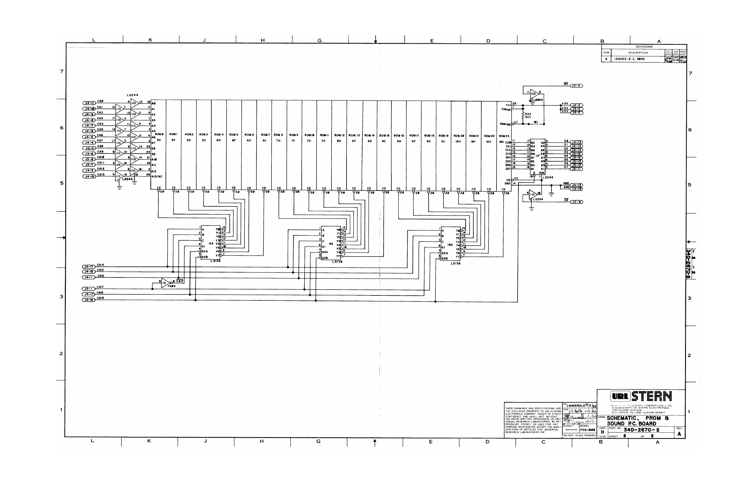
This page is a drawing, shown as the original scan.
| H | S | 4 | | | E | D | c | | | B | | | A |
MONITORS REVISIONS MONITORS O| 3 PIN CONN, | srw DESSRIPTION GEN, TLL DRAWER CABLE SEN. TLL-S¢7o DRAWER CABLE)|_*
in) a "| om | “AD. , pL)! Gen. TLL, ° sous, | x = —<—— key Jur unin sav umes, |
| ae | cnr | ; | |||||
| 7yeLv) | 3< oe | vin" Vout | ape | ||||
| ial | 5 iF | Tel2 | +i2v' ' | | | |||
| ‘8(weT eu} | IN4002, | 1NS391 | a | ||||
| tr 1 | ~* | be | Ag veal | t | ton | | ||
| af | ciheiee To Tar |" wo“) | Tag | ] | ||||
| sie) | 7e | S\p+—_i | aa | ye t | | | T i | i |
| i | fy 2A BB tnaooe | ew | = | “we | “ | ||
| 1@(@RN) | te | tt | ~ |
me
| nowervonmy be | EM | | | ||
| J | = | = | | | |
| 121eRn) | 1 | & ea | rc | ~ | |
i<——_—, S\3+—# ° [ove oe wa 4<—xrev —inddoe
| 3 E | ee | ‘ | — | ||
| I | = inago2 | 14002 | =e is | ||
| (ware | S{RED) | e< | tt | a | : |
| MLK /RED)3_ a | 3< | 7 |
>2 | cod
| (eax/wnTye | eLu) | Se | = | |
FLUORESCENT xFMR (160-42) Cir USED) aida TMESE ORAWINGS AND SPECIFICATIONS ARE PE NERAD vwlasle
Pe SUPPLY P.C. BBOARI JGractume GF ARTICLES FOR UNIVERSAL, en eae Ba Resear CABORATORES x D
| 7 | "i | ; | 7 | 3 | ; | = | 5 | = | icles | a |
Ru R4 R3 4700 | DRIVER A
CONTROL 8B Ison 68n x i 6. a WA
G >! 2|ur2 4, ] . 2ne54e | MTL Ji
2N3904 Leave R_COMMON Se | DRIVER B >3
MOC3010
THESE DRAWINGS ANO SPECIFICATIONS ARE THE EXCLUSIVE PROPERTY OF URL/A STERN | RO Renu ELECTRONICS COMPANY. ISSUED IN STRICT GONFIDENCE AND SHALL NOT. WITHOUT HE PRIOR WRITTEN PERMISSION. OF UP VERSAL RESEARCH LABORATORIES, BE RE PRODUCED, COPIED, OR USED FOR ANY PURPOSE WHATSOEVER EXCEPT THE MAN ~ [4 UFACTURE OF ARTICLES FOR UNIVERSAL 300 Enns AVENSE AL nlizls 20 GROVE MILEAGE LIMOS 60007 REVISIONS
DESCRIPTION
CORRECTED Q1 @ CHANGED Re| @RIZ VALUES E.T. 3038
UNIVERSAL RESEARCH LABORATORIES INC ‘A SUBSIDIARY OF STERN ELECTRONCS
“ave SCHEMATIC, SOLENOID DRIVER UNIT P-C.BOARD PART NO. 34C-2665-S RESEARCH LABORATORIES INC. sHeeT ort
REVISIONS,
DESCRIPTION
ISSUED E.I. 02374
‘CRe4
IN4I4¢8.
+o
10Gnt,16v| ry
IME
PPTNERAD leslie UNIVERSAL RESEARCH LABORATORIES INC HESE DRAWIt SPECIFICATIONS A SUSSIOARY OF STERN ELECTRONICS.
THESE DRAWINGS AND SPECIFICATIONS ARE A SUBSOARY OF STi
ELK GROVE VILLAGE, «UNOS 60007
“WE SCHEMATIC, UNIVERSAL INTERFACE BOARD P.C. BOARD PART NO 34C-2505-S
SHEET i or
This page reads as a drawing: its text was drawn rather than typeset, and comes out in fragments. See the original scan.
x
q REVISIONS
fA nat DESCRIPTION
TSQUED Ex.02448 leigigigis RE 3. o ia a o
a iz PEPE LEERY
38 8 |S 13/s
F bo fo Jo [ee BE | |
FROM SHEET | OF 2
aE aa,
rhe
iil