4 Player Football DP-139-1st-01B
4-Player Football (Atari, 1979) · Drawing Package · 1 pages · original scan
cLock
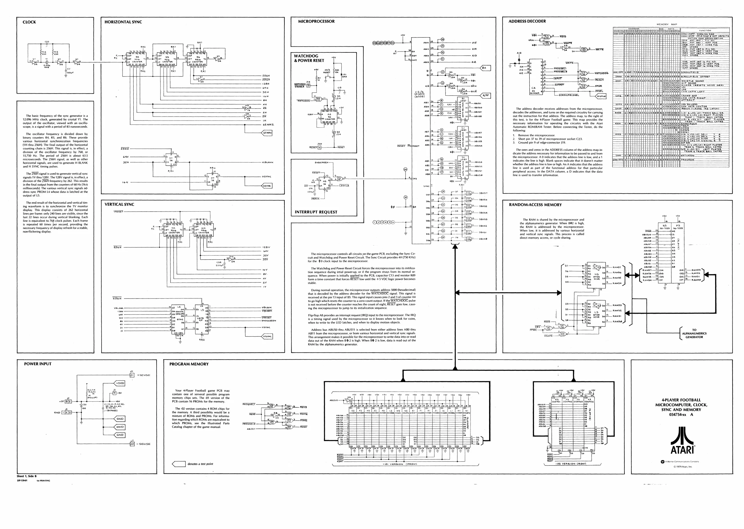
The basic frequency of the syne generator is a 12036 Mitz clock, generated by crystal YI. The ‘output of the oscillator, viewed with an oscillo ‘cope, isa signal with a period of 83 nanoseconds ‘The oscillator frequency is divided down by binary counters R4, R5, and R6. These provide various horizontal synchronization frequencies (1H thew 256H). The final output of the horizontal ‘counting chain is 256H. This signal is, in effect, a division of the oscillator frequency by 768, or 15,750 Hz, The period of 256H is about 635 microseconds. The 256H signal, as well as other horizontal signals, are used to generate H BLANK. and H SYNC timing pulses. ‘The 256H signal is used to generate vertical syne signals TV they 128V. The 128V signals, in effect, a
division of the 256H frequency by 262, This results
in the final output from the counters of 60 Hz (166
milliseconds). The various vertical syne signals ad dress syne PROM La whose data is latched at the ‘output of L5
‘The end eesuit of the horizontal and vertical tm ing waveform is to synchronize the TV monitor display. This display consists of 262 horizontal lines per frame: only 240 lines are visible, since the last 22 lines occur during vertical blanking. Each
line is equivalent to 768 clock pulses. Each frame
is repeated 60 times per second, providing the
necessary frequency of display refresh fora stable,
nomickering display HORIZONTAL SYNC MICROPROCESSOR
a
tow u a | “# os
VERTICAL SYNC
eee mee
ow ay WATCHDOG ” & POWER RESET
‘warase: ase =
“wareRDDE-
INTERRUPT REQUEST
we abe ces,
verx — ADDRESS DECODER
eae Tesox}
‘The address decoder receives addresses from the microprocessor, decodes the addresses, and turns onthe required circuitry for carrying ‘ut the instruction for that address, The address map, to the right of this text, is for the 4Player Football game. This map provides the necessary information for operating the circuitry with the Atari ‘Automatic ROMIRAM Tester, Belore connecting the Teste, do the following:
- Remove the microprocessor.
- Short pin 37 to 39 of microprocessor socket C23
- Ground pin 9 of edge-connectorJ19, ‘The ones and zeros in the ADDRESS column ofthe address map indicate the address necessary for information tobe passed to and from the microprocessor. indicates that the address line is low, and a1 indicates the line is high. Blank spaces indicate that it doesn't matter ‘whether the address line slow or high An A indicates thatthe address Tine is used as part of the functional address for that particular peripheral access. Inthe DATA column, a O indicates that the data line is used to transfer information. ent RRR
WL
‘The microprocessor controls all circuits on the game PCB, excluding the Sync Ci cuit and Watchdog and Power Reset Circuit. The Sync Cieuit provides 4H (750 KHz) for the $0 clock input to the microprocessor. “The Watchdog and Power Reset Circuit forces the microprocessor into its ini tion sequence during intial powers, oF if the program strays from its normal se- RANDOM-ACCESS MEMORY
‘The RAM is shared by the microprocessor and the alphanumerics generator. When 892 is high, the RAM is addressed by the microprocessor When low, itis addressed by various horizontal ‘and vertical syne signals. This process is called direct memory access, or cycle sharing
- ‘quence. When power i initally applied to the PCB, capacitor C13 and resistor R89 “ form a time constant that forces RESET low until the +5 VOC logic power becomes ay stable During normal operation, the microprocessor outputs address 5000 (hexadecimal) that i decoded by the address decoder forthe WATCHDOG signal. This signal is received atthe pin 13 input of 85. This signal input causes pins 2 and 3 of counter 4 to go high which resets te counter oa zero count output If the WATCHOOS pulse {snot received before the counter reaches the count of eight RESET goes low, caus
| yosae | ing | the microprocessor to jump to it intialization sequence |
ing the microprocessor to jump qn Fipflop AB provides an interrupt request (IRQ) input othe microprocessor. The IRQ = na {sa timing signal used by the microprocessor soit knows when to look for coins, r ‘when to write to the LED latches, and when to diplay motion objects. ai ‘Addgess bus ABUSO theu ABUSI1 is selected from either address lines ABO thru 10 [ABT from the microprocessor, of fom various horizontal and vertical sync signal. “ALPHATLUNERNCS oa This arrangement makes posible fr the microprocessor to write data into or read GENERATOR data out of the RAM when 82 i high. When BE 2 is low, data i read out ofthe RAM by the alphanumerics generator.
POWER INPUT PROGRAM MEMORY
Your 4Player Football game PCB may ci Ped
memory chips sets. The 1 version of the we eran a
| PCB contain 16 PROM: forthe memory. | omom | : | fot | tt | fest: [osoa]oxzton]oaS%oe| | 4PLAYER FOOTBALL |
proereT —2ypp a tale dele tole tole eis tos my MICROCOMPUTER, CLOCK,
| ra | ee | rs axeass | Fra baton | ye er cnPepitieh | ha | - | [ice | Pte fe [ve Fes | [ee | Ps | SYNC AND MEMORY |
wo memory. A third possiblity would be a wea eo, ene aaa csi obo
| mature of ROMS and PROMS, For informa: | a | ape | a | = | 034754xx | A |
| | | —<e05] | Convtpordng wich ROne are cae | ‘yer |
= which PROMS, see. the illustrated Parts
| p—<a0] | Catalog chapter of the game manual. | oD | eer |
~ sense
| < | denotes atest point | =o1 Version (PROM) | 02 VeRsion (nom) | ° _——_ |
Sheet 1 Side B Dessert pmin