Asteroids Deluxe Caberat DP-173-1st-01A
Asteroids Deluxe (rev 3) (Atari, 1980) · Drawing Package · 1 pages · original scan
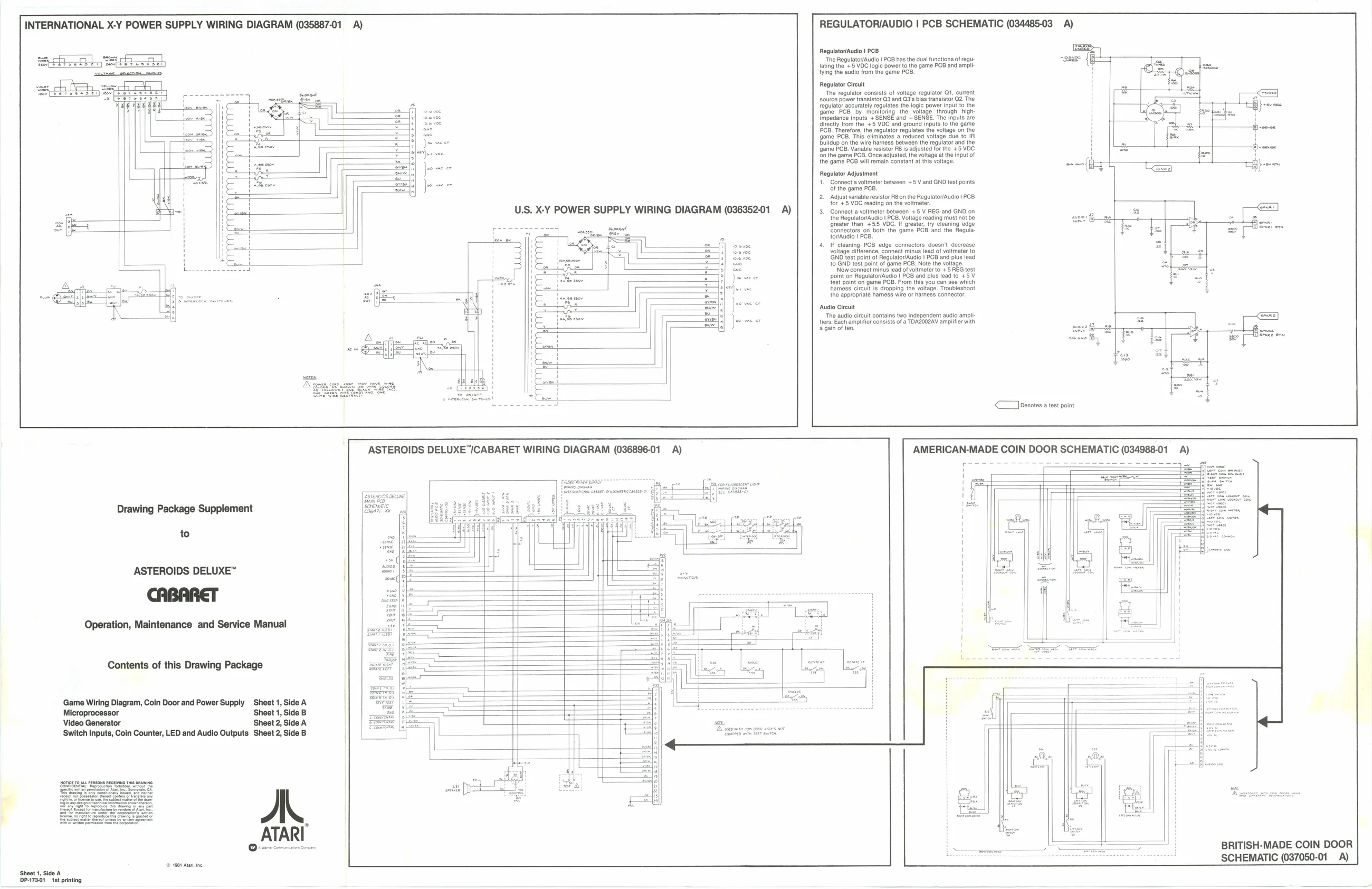
REGULATORIAUDIO | PCB SCHEMATIC (034485-03 A) INTERNATIONAL X-Y POWER SUPPLY WIRING DIAGRAM (035887-01 A)
RegulatoriAudio | PCB ‘The Regulator/Audio | PCB has the dual functions of regu-
lating the +5 VDC logic power to the game PCB and amp
fying the audio from the game PCB.
Ce Regulator Adjustment
1. Connect a voltmeter between +5 V and GND test points
of the game PCB.
- Adjust variable resistor R8 on the Regulator/Audio | PCB for +5 VDC reading on the voltmeter. 3, Connect a voltmeter between +5 V REG and GND on the RegulatoriAudio | PCB. Voltage reading must not be greater than +55 VOC. if greater, try cleaning edge Connectors on both the game PCB and the Regulatov/Audio | PCB.
- If cleaning PCB edge connectors doesn’t decrease voltage difference, connect minus lead of voltmeter to GND test point of Regulator/Audio | PCB and plus lead t0 GND test point of game PCB. Note the voltage.
‘Now connect minus lead of voltmeter to +5 REG test
point on Regulator/Audio | PCB and plus lead to +5 V test point on game PCB. From this you can see which hharness circuit is dropping the voltage. Troubleshoot the appropriate harness wire or harness connector. U.S. X-Y POWER SUPPLY WIRING DIAGRAM (03635201 A)
Audio Circuit ‘The audio circuit contains two independent audio ampli
fiers. Each amplifier consists of a TDA2002AV amplifier with
again often.
<< ownates a test point
Drawing Package Supplement
to
ASTEROIDS DELUXE™
Operation, Maintenance and Service Manual
Contents of this Drawing Package
‘Game Wiring Diagram, Coin Door and Power Supply Sheet 1, Side A
Microprocessor Sheet 1, Side B
Video Generator Sheet 2, Side A ‘Switch Inputs, Coin Counter, LED and Audio Outputs Sheet 2, Side B
A. ATARI BRITISH-MADE COIN DOOR SCHEMATIC (037050-01 A) © 1901 At, ne