Lunar Lander TM-136 3rd Printing
Lunar Lander (rev 2) (Atari, 1979) · Technical Manual · 64 pages · 41 sections · original scan
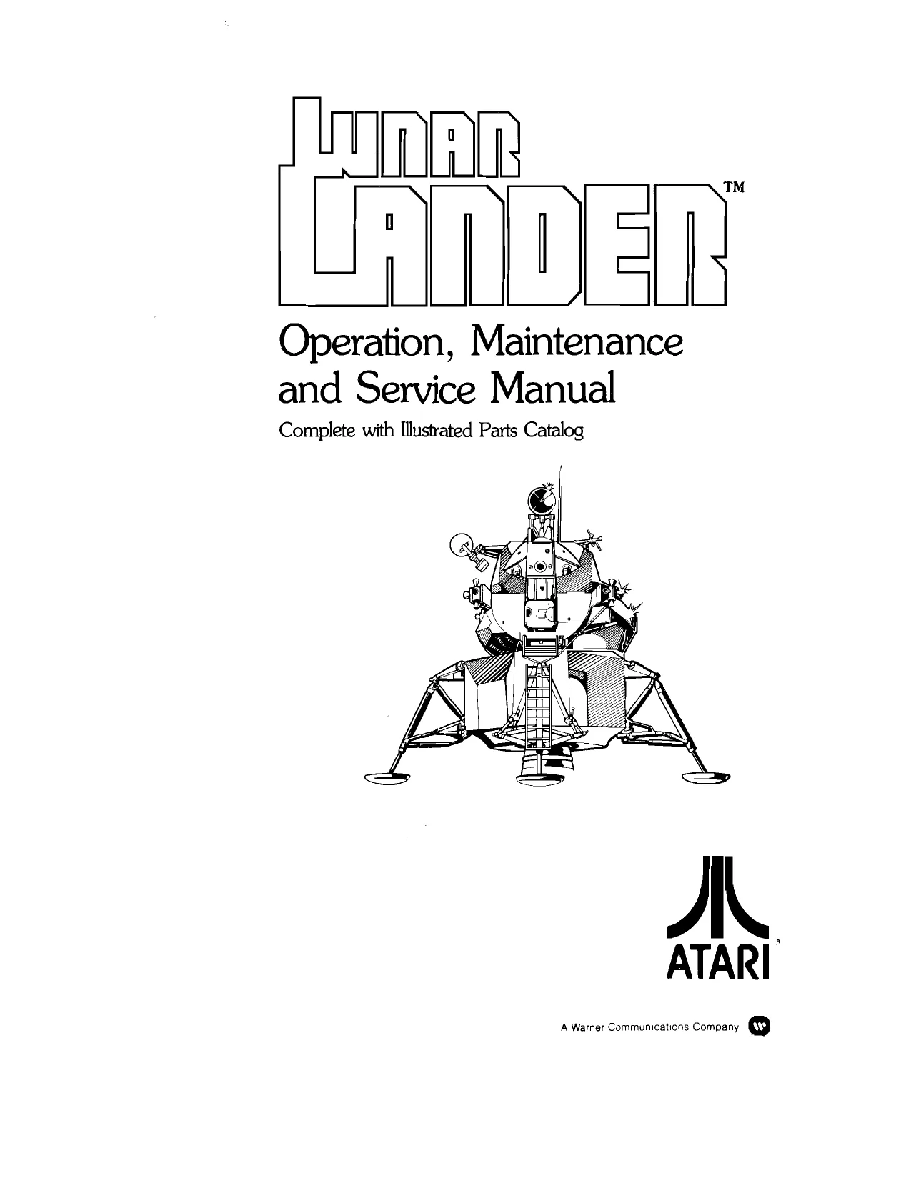
LANDER
yaern Maintenance and Service Manual
Complete with Illustrated Parts Catalog
GAME SERIAL NUMBER LOCATION
Your game's serial number is located on the outside of the game. The same number is also stamped on the chassis of the TV monitor, game PCB and Regulator/Audio PCB. Please mention this number whenever calling your distributor for service.
GAME SERIAL # IDENTIFICATION TAG
REGULATOR/AUDIO PCB
GAME PCB
This page is a drawing, shown as the original scan.
Copyright © 1979 by Atari, Inc. All rights reserved
No part of this publication may be reproduced by mechanical, photographic, or electronic process, or in the form of a phonographic recording, nor may it be stored in a retrieval system, transmitted, or otherwise copied for public or private use, without permission from the publisher.
For permission requests, write:
ATARI INC 1265 Borregas Avenue P. O. Box 427 Sunnyvale, California 94086
10H
Lithographed in the U.S.A
ii Lunar Lander™
table of contents
mOOBD NEWPARTS ... GAME INSPECTION . . VOLTAGE SELECTION : INTERLOCK AND POWER ON/OFF SWITCH .. . SELF-TEST PROCEDURE
game play
A. ATTRACTMODE.......... 0.00 c ccc eee teenies B. READY-TO-PLAY MODE . C. PLAY MODE .... 0.60. ees
maintenance and adjustments
A.
ammo CLEANING ... 0.00 cette tees FUSE REPLACEMENT... . CONTROL PANEL ACCESS 1. LED Switch Replacement
- Mission Seiect PCB Lamp Replacement .
- Thrust Control Maintenance and Repair TV MONITOR REPLACEMENT..........0 0000000 e bet eee cece eee PRINTED CIRCUIT BOARD REPLACEMENT . . 18 FLUORESCENT TUBE REPLACEMENT sesmre ers 1D SPEAKER REPLACEMENT .......... 0000000 c cence tee eneee 19
details of electronic operation
A. DESCRIPTION OF AN X-Y GAME. . 1. 2.
DESCRIPTION OF ELECTRONIC ASSEMBLIES . Rone a. Power Input and Game Output . b. The Microcomputer... . c. The Vector Generator . . The Raster-Type Game ... The X-Y Game
Power Supply Regulator/Audio PCB .. . Control Panel... . . Game PCB..........
illustrated parts catalog
Lunar Lander™ | iii
list of tables
Table 1 Installation Requirements . 2 Table 2 — Self-Test Procedure... . 6 Self-Test Identification of Faulty ROM Chips Option Switch Settings
list of illustrations
Figure 1 Power Supply 3 Figure 2. Location of Interlock and Power On/Off Switches . 4 Figure 3 Location of Self-Test Switch and Volume Control . 5 Figure 4 Location of Operator Option Switch seb ghee Fem i 9 Figure 5 Opening and Removing Parts from the Control Panel . Figure 6 — Thrust Control Lubrication and Repair .. . Figure 7. TV Monitor Removal Figure 8 — Removing Printed Circuit Boards Figure 9 Fluorescent Tube Replacement........ . : : : . 19 Figure 10 Lunar Lander Game Block Diagram ..... 2.000.000 c eee eee 23 Figure 11 PCB Block Diagram .. 2.1.60. teens 24
Figure 12 Final Assembly 2... tee eee Figure 13 Control Panel Assembly Figure 14 Thrust Control Assembly . . Figure 15 Lunar Lander PCB Assembly ......0. 00.00 cece ee eee Figure 16 X-Y Game Power Supply Assembly Figure 17 Fluorescent Light Assembly . . Figure 18 Coin Door Assembly Figure 19 Front Bezel Assembiy Figure 20 Regulator/Audio PCB Assembly
iv Lunar Lander™
If reading through this manual does not lead to solving a certain maintenance problem, call Tele-Help™ at the Atari Customer Service office in your geographical area, as shown in one of the two maps below. Order all parts from the California office.
WEST and CENTRAL U.S.A.
Parts for aii Atari Customers. Sales and Service.
Atari Coin-Op Customer Service 1344 Bordeaux Drive, Sunnyvale, CA 94086 Telex 17-1103
(Monday - Friday, 7:30 - 4:00 pm Pacific Time)
From California, Alaska or Hawaii = (408) 745-2900
From anywhere else in this area “toll-free (800) 538-1611
EAST U.S.A. Sales and Service Only
Atari Inc. New Jersey Customer Service Office Cottontail Lane, Somerset, NJ 08854 Telex 37-9347
(Monday - Friday, 8:30 - 5:00 pm Eastern time)
From New Jersey = (201) 469-5993
ee From anywhere else in this area = toltfree (800) 526-3849
vi Lunar Lander™
This page carries no recoverable text. It is a drawing or a photograph. See the original scan.
a. new parts
The Lunar Lander™ game has five new Atari parts. If you have worked on Atari video games in the past, then you should be aware of these important differences. The new parts are: © Power Supply Assembly. It covers a wider voltage range than before, has higher reliability, a smaller overall size, and all fuse numbers and fuse amperages are marked directly on the metal chassis. © Game PCB Circuitry and TV Monitor. Most video games to date have used the raster scan method of display. This
Lunar Lander ™
game uses vector generation with X and Y axes to allow greater contrast, a greater number of moving objects on the screen, and lines at any angle can be “drawn” on the screen. © Thrust Control. This new design realistically simulates applying engine thrust. Regulator/Audio PCB. Most of the heat-producing components have been moved off the game PCB and onto this smaller board, so the parts will not be prone to a higher rate of failure. ° New Speaker Arrangement. A larger loudspeaker installed in an enclosed wood compartment provides better bass response for the sound. Throughout this manual and illustrated parts catalog, wherever one of these five new parts is mentioned, you will see this symbol in the page man
b. game inspection
This new game is ready to play upon removal from the shipping carton. However, your careful inspection is needed to supply the final touch of quality control. Please follow these steps to help us insure that your new game was delivered to you in good condition.
- Examine the exterior of the game cabinet for dents, chips, or broken parts.
- Unlock and open the rear access panel of the cabinet and inspect the interior of the game as follows: a. Check that all plug-in connectors (on the game harness) are firmly seated. b. Remove the game printed circuit board (PCB) as follows:
- Remove the screws at the edge of the PCB closest to you. © Unplug the edge connector carefully. DO NOT BEND THE PCB. ¢ Slide the PCB out of its slots. c. Verify that all integrated circuits (ICs) are firmly seated in their sockets or soldered in place. You should eliminate any foreign material such as loose bits of wire or solder splashes that could cause unwanted conductive paths. d. Note the location of the game’s serial number—it is on the metallic label in the upper left corner on the back of the cabinet. A serial number (not necessarily the same one) also appears in the corner of the back side of the game PCB that is between the two edge connectors. A drawing of this is on the inside front cover. Please mention this number whenever you call your distributor for service. Carefully slide the PCB back into its slot in the game cabinet and secure with the two screws at the board’s edge closest to you. Plug the edge connector back onto the PCB. DON'T FORCE IT. The connector is keyed so it will only go on in the proper orientation. A reversed edge connector will damage the PCB.
- Check all major subassemblies such as the power supply, loudspeaker (which contains powerful magnets that will attract small metal items—remove these items), and all player-operated controls and switches. Check that the video monitor is securely mounted; tighten the hex nuts below the monitor shelf as necessary.
c. voltage selection
Table 1 Installation Requirements
110 VAC, 60 Hz (nominal), 175 watts OR 220 VAC, 50 Hz (nominal), 175 watts 0 to 38°C (32 to 100°F) Not over 95% relative 65 x 79 cm (251 x 31 in.) 184 cm (721/2 in.) Temperature Humidity Space Required Game Height
Before plugging in your game, make sure that the voltage selection plug on the power supply is correct for your location’s line voltage. Check the wire color on the plug and see if it is correct per the list below.
Line Voltage Range Voltage Selection Plug Color
90-110 VAC Violet 105-135 VAC Yellow 200-240 VAC Blue 220-260 VAC Brown
zs
Figure 1 Power Supply
d. interlock and power on/off switch
To minimize the hazard of electrical shock while you are working on the inside of the game cabinet, two interlock switches have been installed (see Figure 2). One is located behind the rear access panel and one is behind the coin door. These switches remove ail the AC line power from the game circuitry when a door is opened.
Check for proper operation of the interlock switches by performing the following steps:
- Unlock and open the rear access panel and the coin door.
- Plug the AC line power cord into an AC outlet.
- Set the on/off switch to its on position.
- Close the rear access panel and coin door. Within approximately 30 seconds after closing the panel and door, the TV monitor should display a picture (the game lighting should light immediately).
- Slowly open the rear access panel. The TV monitor picture should disappear and the game lighting should go off when the panel is opened to approximately 2.5 cm (1 inch). Close and lock the rear access panel, and repeat this step with the coin door.
INTERLOCK
POWER . ON/OFF SWITCH
Figure 2. Location of Interlock and Power On/Off Switches
VOLUME CONTROL
VOLUME DECREASE: TURN CLOCKWISE
SELF-TEST. SWITCH
Figure 3 Location of Self-Test Switch and Volume Control
- If the results of step 5 are satisfactory, the interlock switches are operating properly. If the TV monitor and game lighting don’t go off as described, check to see if the corresponding interlock switch is broken from its mounting or stuck in the on position.
a. self-test procedure
This game will test itself and provide data to demonstrate that the game's circuitry and controls are operating properly. The data is provided on the TV monitor and the game speakers: no additional equipment is required.
Part of the self-test includes a test of the volume level and by tripping the coin switch wire merely to change the a display of the operator-selected game options. Therefore, volume level during game play. we suggest you run the self-test anytime you need to adjust the volume or change the options. Besides, this method will To begin the self-test, follow the instructions outlined in eliminate an inaccurate coin count, which would be gotten Table 2.
Table 2 Self-Test Procedure
Preliminary: With power on, slide self-test switch towards rear of cabinet or on (see illustration). This switch is located on a metal bracket just inside the coin door. Game advances through all tests automatically, except when it fails in Test 1 or 2. In such a case, it will stop wherever it finds a failure. Lunar Lander will not be able to finish the self-test procedure until the defective RAM(s) is replaced.
| Name of Test/ | Result if Test Passes | Result if Test Fails |
Instructions
| 1. | Zero Page RAM Test | Select and Start switches light and stay | Screen stays blank and never displays |
lit. Screen is blank. any characters of Test 3.
Two short medium-high beeps are One or both beeps are very high pitch sounded (3000 Hz). (6000 Hz), meaning bad RAM(s). Ast beep very high = bad RAM at location D2 on game PCB
2nd beep very high = bad RAM at location E2
| 2. | Vector Generator | Four long medium-high beeps are | One or more of the beeps are very high |
| (Screen) RAM Test | sounded (3000 Hz). | pitch (6000 Hz), meaning a bad vector |
generator RAM. Ist beep very high = bad RAM at M4 2nd beep very high = bad RAM at R4 3rd beep very high = bad RAM ai N4 4th beep very high = bad RAM at P4
ROM OK appears in upper left comer & is displayed in upper left corner of of screen. screen, indicating bad or missing ROM at location N/P3 or PROMs at locations, K4 and L4.
; One or more numbers 0 thru 27 will be displayed, indicating a bad ROM or PROM: see Identification of Faulty ROM Chips list on page 8.
Name of Test/ Result if Test Passes Result if Test Fails Instructions
- Option Display Option settings are displayed in center of screen, as shown in photograph above. The first line shows one of 8 different numbers (see Option Switch Settings list on page 10) or an “X” to indicate free play setting. Message will be in one of four available languages. The second line shows the right coin mechanism factor — it will be 1, 4, 5, or 6.
- Thrust Control Test Push thrust control slowly towards rear of game. Two characters don’t change at all, or skip numbers, indicating a dirty potentiometer. Decreasing numbers as you push control means harness wires have been reversed. Thrust control at rest and numbers changing rapidly indicate harness wires are loose. The third line shows two characters: they should increase. “Flickering” numbers while control is at rest are unimportant and should be ignored.
One or more lights won’t go on, indicating a defective light bulb.
- Lamp Audio, and LED Test Four mission select lamps light sequentially from right to left. (Instructions lamp is always lit.)
No engine thrust or crash sound means volume control too low, a defective speaker, loose speaker wires, or a problem in the audio circuitry. Engine thrust sound increases with each light from right to left. With Training Mission light on, you'll hear instead the crash sound. Now adjust volume for your location.
One or both of the Select and Start switches do not flash on, indicating bad LED switches or loose hamess wires. Between the end and beginning of the four-light sequence, both Select and Start switches go on in unison for a moment.
- Switch Test Press each of these switches: © 5 LED switches on control panel
- 2. coin switch trip wires slam switch on coin door High beep is sounded for each change in switch state, ie., a push and release should produce two beeps. No beep indicates a defective switch or loose harness wires.
Slide the self-test switch towards the front of the game or off. Note that using the self-test will cause all the numbers at the top of the screen to reset to zeroes.
Identification of Faulty ROM Chips
Display During -01 P.C, Boards Self-Test (PROMs) Alternate -01 P.C. Boards (PROMs) -02 P.C. Boards (ROMs)
035176-01 K4 035177-01 034599-01 R3.
035174-01 K4 035175-01 034598-01 N/P3
034600-01!
034601-01! La 034597-01! M3
034579-xx 034580-xx 034587-xx 034588-xx 034592-xx 034572-xx FL
034577-xx 1034578-xx 034585-xx 034586-xx 034575-xx 034576-xx 034583-xx 034584-xx 03457 1-xx D/E1
034570-xx C1
034573-xx No display 034574-xx. at all 034581-xx 034582-xx 034589-xx? K2 034593-xx? L1 034569-xx? BI
!These chips contain only the French, German and Spanish messages. If the game is to be operated in the English language, you do not need to replace them. In fact, they may not even be supplied on a printed circuit board intended for use only in English-speaking areas. Thus in such a case you should ignore the 8 9 10 11 “bad” ROM message.
2ROM or PROMs must be in place for self-test to work.
-xx after some of the part numbers above means that the chip can be either an -01 or -02 version. The difference between the two versions is in the operator option switch settings. First note what part numbers and versions are stamped onto the ROMs on your PCB; then refer to page 10 in the manual for the switch settings that correspond to your version.
Haag HAAS
OPERATOR ‘OPTION SWITCH
GAME PCB er’
Figure 4 Location of Operator Option Switch
Option Switch Settings
To change the toggle positions of the switch assembly, you need not remove the PCB. The switch, usually colored blue, is easily accessible when the PCB is left mounted in place. Unless you are a qualified technician, do not turn any of four adjustments knobs near the PCB’s edge connector.
Your game will contain either of two different sets of program ROM/PROM chips. Check your game PCB io see which suffix is stamped after the part numbers on these chips (-01 or -02). Then refer to the appropriate table below to determine your game’s option switch settings. Option Switch Settings with -01 ROMs on Printed Circuit Board
Switch settings of 8-Toggle DIP Switch (located at positon P8 on the om ra 450 fuel units per coin 600 fuel units per coin 750 fuel units per coin 900 fuel units per coin
Free play Coined play as determined by toggles 7&8 $
*German instructions on screen *Spanish instructions on screen *French instructions on screen English instructions on screen $
TOGGLE UNUSED
Right coin mechanism (as you face the game) registers: 1 credit per coin $ 4 credits per coin (Left coin mechanism always 5 credits per coin registers 1 credit per coin) 6 credits per coin
Switch Settings of 8-Toggle DIP Switch (located at position P8 on the game PCB)
450 fuel units per coin 600 fuel units per coin 750 fuel units per coin 900 fuel units per coin 1100 fuel units per coin 1300 fuel units per coin 1550 fuel units per coin 1800 fuel units per coin
*German instructions on screen
- Spanish instructions on screen
o *French instructions on screen
English instructions on screen $
Right coin mechanism (as you face the game) registers: 1 credit per coin $ 4 credits per coin (Left coin mechanism always 5 credits per coin registers 1 credit per coin) 6 credits per coin
*IMPORTANT: When changing instruction language switches, the six phrases at the top of the screen will remain in the previous language; only the FUEL UNITS PER COIN phrase will change immediately. When the lander ‘crashes’ {in the attract mode) the language will reset completely. In free play, the language will reset when the start button is pressed. $ indicates settings made at the factory and/or recommended settings
Lunar Lander™ is a one-player coin-operated electronic game that simulates landing a manned spaceship on the moon. Various video-display phrases indicate score, time elapsed during this landing mission, fuel units consumed, altitude above the moon, and horizontal and vertical speed. The fuel consumption and both speed readings are important for the player to determine how to land the craft. Realistic engine rumble and crash sounds accompany game play. A high beep warns of an almosi-depleted fuel supply, whereupon players can add coins to automatically extend the game and “fill up” their fuel tanks. Depending on the quality of the landing or the crash, various messages are displayed on the screen.
The Lunar Lander game has four basic modes of operation: attract, ready-to-play, play and the self-test. The attract mode starts after power-up, after the play mode, or after the self-test. It ends when a coin has been inserted into either
game play
coin slot. The ready-to-play mode follows the attract mode and begins after a coin has been inserted. It ends with the pressing of the LED start switch.
The play mode begins immediately after the ready-toplay mode, when a player presses the start switch. (The game does not automatically start after a certain time has elapsed, i.e., pressing the start switch is the only way Lunar Lander will begin the play mode.) The self-test is a special mode used for verifying proper game operation. It begins with the self-test switch set to on, and ends when the switch is set to off.
a. attract mode
The attract mode is specifically programmed to attract potential players by displaying the basic sequence of game play. The lander module flies horizontally across the screen, drifting slowly towards the bottom right corner. At the end it “crashes” into a canyon wall. (The actual slow-motion explosion is not displayed, though, as an incentive for players to try out the game.)
The sequence is reset, and a new landscape panorama is displayed. The center of the screen displays the message IN- SERT COINS and xxx FUEL UNITS PER COIN in English or one of three foreign languages. The previous game score is displayed after the word SCORE for player encouragement.
b. ready-to-play mode
This mode starts when either coin switch is activated by a coin. The messages SELECT OPTION, PUSH START and xox FUEL UNITS appear on the screen until a player pushes the LED start switch.
c. play mode
Similar to the attract mode, actual game play begins with engine rumble and the lander drifting towards the bottom right corner of the screen. Horizontal and vertical speeds are constantly displayed, including two arrows to show horizontal and vertical directions of travel. Altitude is measured in distance above the surface of the mountain — not above “sea level”. The screen also shows time in actual seconds, representing time elapsed in the current mission.
The scoring system gives 50 points for a good landing, plus 50 fuel units as a bonus. A hard landing earns only 15 points, and a crash earns 5 points. A crash happens when the vertical speed exceeds 15 and the horizontal speed exceeds 31. The number displayed after SCORE is cumulative of all landings made in the current game. The point scores for a good or hard landing can be greatly increased by landing on an area with a flashing multiplier, for example 2X or 5X. Thus, a good landing on the very narrow 5X site would give that player 250 points.
As already mentioned in Chapter 1, the operator can select from up to eight different settings for fuel units — 450, 600, 750, 900, 1100, 1300, 1550 or 1800 fuel units per coin (free play is also available). As the lander module flies over the landscape, it approaches the mountains and a landing site. At a certain point near the mountains, the game “zooms in” for a close-up view of the landing zone.
If the player realizes the speed is too fast and the landing looks hopeless, he or she can press the ABORT button on the control panel. This will give the lander extra thrust and make it fly upwards at top speed. The abort feature does consume 120 to 180 fuel units, though, as a disincentive to overusing it. If the ABORT button is pressed too late, however, a crash cannot be avoided.
The four levels of mission difficulty are determined by the player and can be changed at any time during the game or the ready-to-play mode. The differences between the four are printed on the mission select panels and are selfexplanatory, except perhaps rotational momentum. This feature causes the lander to tumble around when either ROTATE button is pushed. The longer either button is held down, the faster the lander module will spin in that direction. The player gains control of the lander by pressing the other ROTATE button for the same amount of time.
maintenance
and
adjustments
Due to its solid-state circuitry, this Atari unit should require very little maintenance and only occasional adjustment. Information given in this chapter and elsewhere in this manual is intended to cover most servicing situations that may be encountered at the game site. The procedures given are in sufficient detail to be understood by a person with moderate technical background.
R Fl, F2, F3 The exterior of the game cabinet and the three acrylic panels may be cleaned with any non-abrasive household cleaner. If desired, special coin machine cleaners that leave no residue can be obtained from your distributor. Do not dry-wipe any of the acrylic panels, because any dust can scratch the surface and result in fogging the plastic.
b. fuse replacement
This game contains six fuses—all on the power supply assembly (not including the TV monitor fuses). Replace fuses only with the same type as listed below. See the Electrohome TV monitor manual for the monitor fuse data.
7-amp. 250V 3AG slow-blow glass cartridge-type fuse 3-amp. 250V 3AG slow-blow glass cartridge-type fuse F4, F5, F6
The metal power supply chassis is marked with all six fuse numbers and their amperages. Figure 16 shows the power supply in detail, including top and bottom views.
c. control panel access
Prior to repairing or replacing any component on the control panel or prior to removing the TV monitor, unplug the game. Then open the coin door.
Reach through the opening and remove all four sets of wing nuts, split lock washers, and flat washers, located on the underside of the control panel (see Figure 5). The two carriage bolts closest to the front of the game will come out of the control panel; at this point in the procedure the rear two bolts are left as installed.
Lift up on the control panel and tilt it towards you. Be sure that the acrylic TV monitor shield does not fall on you. The top edge of the control panel acts as a retainer strip for the shield: once the control panel is opened, the shield is free and could slide out under its own power.
- LED Switch Replacement The light-emitting diode (LED) switches on the control panel have a very low failure rate. In case a switch should ever be suspect, first test it per the description that follows. To replace the switch, refer to Figure 5.
- Remove the wires from the suspected switch.
- Set multimeter to ohms scale. Set ohms scale to R x 1, then zero the meter.
- Connect multimeter leads to appropriate LED switch contacts. (See Figure 5 for designation of switch contacts and meter lead placement.)
- Check contacts (push and release the switch button) for closed and open continuity. . If the contacts do not operate sharply or always remain closed or open, then replace the LED switch as outlined in Figure 5. ot
2. Mission Select PCB Lamp Replacement
With the control panel open, be sure power is turned off. Unplug the harness connectors closest to this PCB. Carefully remove both cross-recessed screws plus the four fiber washers used to mount the board. Replace any of the burned-out lamps. (See Figure 5.)
To re-install the board, be sure the edge with the harness wires faces down towards the floor. Place a fiber washer on either side of the board’s mounting hole, insert each screw and fasten the board down onto the wood framework of the control panel. Re-plug the harness connector together again.
- Thrust Control Maintenance and Repair To maintain this control, you will only have to lubricate the nylon bearings and the springs approximately every
MISSION SELECT PCB
THRUST CONTROL ASSEMBLY
LED SWITCH TESTING
COMMON
CONTACT LIGHT-EMITTING
DIODE (L.E.D.) CONTACTS
NORMALLY OPEN (N.O ) CONTACT \— NORMALLY CLOSED (N.C.) CONTACT
L.E.D SWITCH: TO REMOVE TURN COUNTERCLOCKWISE
- Remove all wires from the faulty switch. |
- Turn the switch counterclockwise while N.O. holding the cone-shaped nut on the out: ° side of the control panei. SINGLE-POLE DOUBLE-THROW (SPDT)
- Install a new switch using the reverse SWITCH WITH INTERNAL LED procedure.
- Reconnect the harness wires. Figure 5 Opening and Removing Parts from the Control Panel
2500 credits or $625 in income eared. The number of credits can be read off the coin counter, located on the coin door. For the thrust control, use only a small amount of Dow Silicon Grease Type 14770-79, Atari part no. 78-1708. Refer to Figure 6 for exactly where to lubricate the thrust control.
Lubricate Springs. Open the control panel and be sure the game’s power is turned off. For lubrication you do not need to remove the whole thrust control assembly. To lube the springs, remove both by slipping them sideways off the ends of the pins. Then apply a small amount of the Dow silicon grease to the two outer recessed grooves on each pin that holds the springs. (See the heavy arrows in Figure 6.)
Lubricate Nylon Bearings. The large pin that is protected by white nylon bearings must be removed before you can lubricate it. First remove the two springs, then the Allen-head screw and split lock washer in the center of the handle. While holding the control’s handle, carefully pull out the pin that rides on the bearings. Be aware that the flat white washers may fall onto the control panel as you remove this pin. Now apply grease only where the bearings normally ride. Reassemble the handle, pin, screw and washers in reverse order.
Repairs on this control, if any, would probably be replacing a broken spring or potentiometer, or trading/replacing neoprene stops that have become dented. Replacing springs has already been explained above.
Potentiometer Replacement. To determine if the potentiometer is defective, run the self-test (see Table 2). If the numbers displayed on the screen are in erratic sequence as
Vv = LUBRICATE HERE ONLY
WITH DOW SILICON GREASE TYPE 14770-79 (ATARI PART NO. 78-1708).
Figure 6 Thrust Control Lubrication and Repair
you move the handle slowly forwards and backwards, then the pot is bad. Simply remove the harness wires on the pot, then remove the hex nut and flat washer that mount the pot on the black metal bracket. Slide the pot out sideways and replace it with a new one. Note that this potentiometer has been modified to include a tiny pin: an off-the-shelf pot cannot be used for this game! Replace with Atari part no. AG34117-01.
Neoprene Stop Replacement. The neoprene stop most likely to wear is that on which the handle sits when in its rest position. The lifespan of this stop can be increased by trading it with the other stop. To trade or replace the stops, remove the E-rings at the ends of the pins. Pull the pins out sideways and replace the stops.
Disassemble in the order indicated Thrust Control Removal. If you ever need to remove the entire thrust control assembly from the game, be sure the power is turned off first. Remove the harness wires on the potentiometer. Then remove the four sets of hex nuts, split lock washers and carriage bolts from the thrust control assembly. Lift the control and its black plastic cover out of the control panel. (See Figure 5.)
d. tv monitor replacement
If you should need to service or replace the Electrohome X-Y monitor, you must first remove it from the game cabinet. Follow the instructions below, and refer to Figure 7.
Figure 7 TV Monitor Removal AS
- Open the control panel as described in Section C, Control Panel Access. Be sure the game is unplugged from its wall outlet!
- Remove the acrylic TV monitor shield by sliding its lower edge out.
- Working up from the bottom side comers, carefully pry loose the two side flaps of the black cardboard bezel. (A 4-inch strip of double-sided adhesive tape is centered behind both side flaps, flush with each edge.) Remove the bezel.
- Open the rear access panel and unplug the following two TV monitor harness connectors: each one is a 6-pin connector on the TV's PCBs.
- Remove the four sets of carriage bolts, flat and split lock washers, and hex nuts that hold down the metal TV chassis.
- Carefully slide the TV monitor chassis out the front of the game.
e. printed circuit board replacement
You may wish to remove the game printed circuit board (PCB) or the Regulator/Audio PCB for service or inspection. To do this, refer to Figure 8 and proceed as follows:
- Open the rear access panel.
- Locate the securing screws and fiber washers that hold down the PCB in its slots, and remove them. (The game PCB has two, the Regulator/ Audio PCB has one set of this fastening hardware.)
- Unplug the edge connector or the three small harness connectors; then carefully slide the PCB straight out of its slots. Be careful not to twist the board, as this may loosen connections or components.
- Replace or repair as required.
- Reinstall the PCB, making sure that the connectors are properly plugged in. Note they are keyed to fit on only one way, so if they don'tslip on easily, don’t force them! A reversed connector may damage the game. REGULATOR! AUDIO PCB
LUNAR LANDER GAME PCB
Figure 8 Removing Printed Circuit Boards
- Replace the securing screws and fiber washers in the PCB.
- Close and lock the rear access panel.
- Check that the operation of the game is correct and perform the self-test. This is especially important with any game when you replace a PCB. Normally the only adjustments on the Lunar Lander game PCB are option switch changes (made on the 8-toggle DIP switch). Unless you are a qualified technician, do not turn any of the four knobs near the PCB's edge connector.
f. fluorescent tube
replacement
To replace the white fluorescent tube behind the graphics attraction panel, follow this procedure (see Figure 9):
- Remove the three Allen-head screws at the top of the game. They secure the metal retainer for the silkscreened panel. Remove the retainer completely.
- Tilt the top of the acrylic panel towards you, then lift it up and out of the bottom retainer.
- Remove the two grey clips from the fluorescent tube. Now turn the tube one quarter turn in either direction. Remove the tube and both orange clips.
- Replace with a new tube. If you move games a lot from one location to another, you should re-use the orange and grey clips. They provide extra protection against vibration loosening the tube out of its fixture.
- Close up the game by following these instructions in reverse order.
g. speaker replacement
Probably the only cause of speaker failure is an electrical short or a ruptured cone, but both of these failures are highly unlikely. If the loudspeaker should ever need to be replaced, removal is very simple.
Remove the six sets of black Allen-head screws and split lock washers that secure the speaker grille. Now remove the four cross-recessed screws that hold down the speaker. Remove the harness “Fast-On” connectors on the speaker and replace this speaker.
Figure 9 Fluorescent Tube Replacement
This page carries no recoverable text. It is a drawing or a photograph. See the original scan.
details of operation
c
With this manual you received two large sheets that contain the wiring and schematic diagrams for the Lunar Lander™ game. Sheet 1, Side A, includes an index that shows the arrangement of these diagrams. The diagrams include information that explains the functions of the circuits and defines where the inputs are from and where the outputs go. We hope these larger schematics solve the problems some technicians were experiencing with the smaller diagrams in our previous manuals. By putting them on large sheets, we were able to make them much easier to read, as well as maintaining smoother continuity from one circuit function to another.
a. description of an x-y game
As stated on the front cover of this manual, this is Atati’s first X-Y game. What's the difference between an X-Y game and Atari’s previous games? To answer this, let’s first discuss our previous games.
- The Raster-Type Game
All previous Atari video games utilized a raster-scan monitor. These games contained a monitor that internally produces signals that scan the beam across the face of the picture tube screen. The beam, as in your home TV, starts ai the top left comer of the screen, moves horizontally across to the right of the screen, turns off, moves down a little while returning to the left of the screen, turns on, and again, moves to the right of the screen. This is repeated until the beam reaches the bottom right corner. The beam is then turned off while it is moved ail the way back to the top of the screen, then the process is repeated over and over. The result is many horizontal lines (240 lines is typical in our raster games) on the surface of the screen, scanned so fast that the screen appears to be lighted all the time.
In these games, the game PCB electronic circuitry is synchronized with the beam and turns the beam on and off, as required to produce the appropriate game video.
- The X-Y-Type Game
This type of game utilizes a monitor known as an X-Y monitor. In the X-Y game, the first thing you will notice is that the picture tube beam is not continuously scanned. Therefore, the game PCB does not contain a standard sync circuit. Instead of the beam being internally controlled by the monitor, the game PCB controls the location of the beam at all times. As in the raster-scan monitor, the yoke of the X-Y monitor deflects the beam. The picture of the X-Y game is produced by drawing vectors on the surface of the monitor screen. This is done by the vector generator circuitry of the game PCB. This circuitry locates the beam in steps. There are 1024 steps for the horizontal location of the beam, and 768 steps for the vertical location. Therefore, there are 786,432 resolution bits (768 x 1024) on the surface of the X-Y monitor screen. Since our typical raster-scan garne has only 61,440 resolution bits (256 line bits x 240 lines), the X-Y game is capable of developing a picture with much finer detail.
The vector generator draws vectors on the monitor by turning the beam on while deflecting the beam horizontally and/or vertically. An increase of the horizontal deflection current moves the beam to the right. Decreasing this current
22> Lunar Lander™ moves the bearn to the left. Increasing the vertical deflection current moves the beam up. Decreasing this current moves the beam down. Increasing both deflection currents simultaneously at the same rate results in a vector that slopes upward and to the right at a forty-five degree angle. By controlling the amount of horizontal and vertical deflection current, the vector generator is capable of “drawing” a line between any two given points on the monitor screen.
The X axis output of the vector generator is the horizontal axis of the monitor, while the Y axis is the vertical. The Z axis output of the vector generator controls the brightness of the beam. Without the brightness control, a short vector drawn in the same amount of time as a long vector would result in the short vector being brighter than the long vector.
b. game wiring and power
distribution
The wiring diagram for the Lunar Lander game is located on Sheet 1, Side A, of the large sheets that came with this manual. Included on this sheet are the schematics for the power supply, Regulator/Audio PCB, Mission Select PCB, and coin door.
Figure 10 of this manual shows the distribution of the power of this game.
c. description of electronic
assemblies
The following section describes the electronic assemblies within the Lunar Lander game. Some of these new designs are, X-Y monitor, Regulator/Audio PCB, X-Y game PCB, and Power Supply. For information concerning the X-Y monitor, please refer to the monitor manual that is included with the game.
Figure 11 of this manual shows the distribution of signals of the game.
- Power Supply The Power Supply is located on the floor of the game cabinet. This supply was specifically designed to provide the voltages required for both raster and X-Y games. Some of the features of this new supply include: a new transformer with greater power output and additional secondary windings; one unregulated DC voltage output, and various AC voltage outputs; a line filtered AC line input; appropriate a)
ATTRACTION PANEL LIGHTING
MONITOR
120 VAC
REGULATOR/AUDIO PCB
COIN DOOR GAME PCB
10.8 VDC UNREG.
10.3 VAC UNREG
\ \
POWER SUPPLY
Figure 10 Power Distribution
SPEAKER
MONITOR
REGULATOR / AUDIO PCB.
CONTROL PANEL
COIN DOOR
GAME PCB
Figure 11 Signal Distribution
sy. voltage selection plugs for four differnt ranges of AC line voltages; and a bank of fuses located on an easily accessible fuse block, with fuse values plainly labeled beside each fuse. (See Chapter 1, Section C, for location of power supply fuses and instructions for the voltage selection plug.)
- Regulator/Audio PCB The Regulator/Audio PCB is the smaller PCB, located on the left wall (standing in front of the game) of the cabinet. It was designed for two reasons: 1) to remove high-heatproducing components from the game PCB, and 2) to provide better regulation of the +5 VDC logic power for the game PCB. A description of both the regulator and audio sections of the PCB is included on Sheet 1, Side A, of the large sheets included with this manual. The schematic for the audio section is repeated on Side B of the sheet.
- Control Panel The control panel on the front of the game includes the Lunar Lander Mission Select PCB, Thrust Contro!, and four LED pushbutton switches.
The Mission Select PCB contains five #1816 lamps. Lamp 1, the INSTRUCTIONS lamp, is always on, as it is connected between +10.3 VDC and two diodes to ground. The other four lamps are lighted by signals LAMP2 thru LAMP5 from the output of the game PCB. These lamps are connected between + 10.3 VDC and the collector of a transistor for each lamp. When the base of a transistor is low, the associated lamp is off. When the base voltage goes high, the lamp lights.
The Thrust Control contains a 5K ohm potentiometer that is connected between +5 VDC and ground. The wiper of the potentiometer is connected to the POTIN input of the game PCB. There is no calibration necessary for this control.
The four pushbuttons on the control panel each have light-emitting diodes (LEDs) inside their buttons. The ROTATE LEFT and ROTATE RIGHT switches are always lighted. The SELECT and START switches are lighted by the START/SELECT output signal from the game PCB. When this signal is high, the LEDs in both the SELECT and START switches are unlighted. When this signal is low, both switches are lighted.
- Game PCB The game PCB is the larger PCB located on the left wall of the cabinet. This PCB contains power input regulators, a microcomputer, audio generator circuit, vector generator (actually a second microcomputer), and video output circuit. a. Power Input and Game Output The power input circuitry to the game PCB is described on Sheet 1, Side B, of the large sheets included with this manual. Also included on this side of Sheet 1 is the schematic and functional descriptions of the game PCB’s mission select output, audio output, and video output.
b. The Microcomputer The microcomputer of the game PCB consists of a microprocessing unit (MPU), a clock circuit, a power reset and watchdog counter, NMI counter, address decoding circuit, program ROM memory, and program RAM memory. See Sheet 2, Side A of the large sheets for the schematic diagram and functional descriptions of this circuitry. This sheet also includes the schematic diagram and functional descriptions for the player control inputs to the game PCB.
A memory map is included in the address decoding circuit block of the microcomputer schematic. The memory map identifies the addresses that the MPU uses to gain access to its peripheral circuits. The ones and zeroes in the ADDRESS column indicate the address necessary for information to be passed to and from the MPU. A zero indicates that the address line is low, and a 1 indicates the line is high. Blank spaces indicate that it doesn’t matter whether the address line is low or high. An A indicates that the address line is used as part of the functional address for that particular peripheral access. In the DATA column, a D indicates that the data line is used to transfer information.
c. The Vector Generator ‘ we
The inputs and outputs of the vecior generator circuitry are defined on Sheet 2, Side B, of the schematic package with this manual. This circuit is in itself a semi-smart microcomputer. It receives instructions from the “game” microcomputer and once instructed what it is to do, it executes the instruction. When it is finished, it tells the microcomputer, via the HALT signal from the SINP1 switch input port, that it is through and is waiting for its next instruction.
All of the picture data on the monitor screen is stored in the program memory of the vector generator. The vector generator RAM receives information from the game microcomputer that tells it what video should be displayed, i.e., rotation of the lunar lander, amount of lunar lander thrust, messages to be displayed on the monitor, etc. The vector generator then accesses this appropriate video stored in its ROM memory and outputs it to the X-Y monitor display.
oo
illustrated parts catalog
The purpose of this chapter is to provide you with the necessary information for ordering replacement parts for the Lunar Lander™ game.
When ordering parts from your distributor, give the part number, part name, applicable figure number of this catalog, and serial number of your game. This will help to avoid confusion and mistakes in your order. We hope the results will be less downtime and more profit from your game.
seco NN
NOTICE TO ALL PERSONS RECEIVING THIS DRAWING IAL: Reproduction, forbidden without the permission of Altai, Ine.” Sunnyvale “drawing is only conditionally issued, neither receipt nor possession thereat confers or transfers iconse to use, tne ‘design or technical. Informal thereon, nor any right to reproduce thereo! except for manufacture by Ve porated and for manutacture under the corporat fen license, no right tor othe subject matter ‘with or writen perm reduce this drawing is gra eof unless by written agreement fon from the corporation,
Figure 12 Final Assembly A034480-01 C
- 2ACS 2-REQD, 2:PLCS
- 2 2ea'0. ZAcs (over)
2-PLCS
SNF ALS
FLUORESCENT LIGHT.
7 PLCS, TYP. GND — (ATTACH @RN- WIRES AS. SHOWN)
NOTICE TO ALL PERSONS RECEIVING THIS DRAWING CONFIDENTIAL: Reproduction forbidden without specific written permission of Atari, inc. Sunnyvs California *his drawing is only conditionally issued, ani either receipt nor possevsion there! conters or wansiers any right in, o” license 10 use, the subject matter of the fawind oF any design or technical formation shown thereon, nor any rigntto reproduce this drawing or any part tMhereol, except for manufacture by vendors of Atari incor porated and for manufacture under the corporation's wrt fen license, no right to reproduce this drawing is granted ‘oF the subject matter thereof unless by wr With or written permissien tro | vountest jnneecoce fl
Figure 12 Final Assembly, continued A034480-01 C \2 op
Figure 12 Final Assembly Parts List
[Tem [ Peano [Ow | Dect SSCSCSCSCSCSCSCS*d A034470-01 A034460-01 A034517-01 A034230-01° A034485-01 A034561-01 A034626-01 A034628-01 A034841-01 A030268-01 030269-01 030249-01 030247-01 030245-01 A009083-16 A034519-01 Cabinet Assembly Contro! Panel Assembly — see Figure 13 Door Panel Assembly Lunar Lander PCB Assembly (PROM version) — see Figure 15 Regulator/Audio PCB Assembly — see Figure 20 X-Y Game Power Supply Assembly — see Figure 16 Main Harness & Component Assembly Light & Speaker Harness Assembly Power Cord Assembly Coin Box Assembly, consisting of the following 4 items: Cash Drawer Separator Handle Lid Coin Door Assembly — see Figure 18 Fluorescent Light and Panel Assembly, consisting of the following two items: Wood Panel for Fluorescent Light Fluorescent Light Assembly — see Figure 17 Speaker Grille Attraction Panel with Graphics Monitor Shield Upper Attraction Shield Retainer Lower Attraction Shield Retainer Bezel Lunar Lander Technical Manual w/ Illustrated Parts Catalog Panel Mounting Bracket Rear Door Seal Copyright Decal (1979) Coin Box Bracket Interlock Switch Cover On/Off Switch Cover Connector Mount CoOrnauewone Pee ee eee eee eee
034478-01 4034752-01 034457-01 034513-01 034467-01 034515-01 034516-01 034518-01 TM-136 001638-01 005233-01 006319-04 006870-01 007882-02 007103-01 030868-01 NEM EE NE Ee eee eee
- A034230-02 is an acceptable substitute (ROM version) — see Figure 15
ATART
034536-02 DP-136-01 DP-136-02
72-6812S
75-015S 75-030S 75-035S 75-040S 75-045S 75-050B 75-5120N 82-1816S 75-5520B 75-5528B 75-911C 75-915C 75-990505S 82-1824S 82-8016 92-042 75-07017
72-1406S
99-11006 70-303 A021084-01 A021084-02 A021084-04 A021084-05 75-99518 75-935 Figure 12 Final Assembly, continued
WE HAROAN INAH UAA AA
iX}
Pye Eee ED Parts List
Foam Dampener Sheet 1, Lunar Lander Schematic Drawing Package Sheet 2, Lunar Lander Schematic Drawing Package 8” High-Fidelity Speaker #6 x 5/8” Cross-Recessed Pan-Head Type AB Zinc-Plated Steel Thread-Forming Screw #8 x 3/4” Cross-Recessed Pan-Head Type AB Zinc-Plated Steel Thread-Forming Screw #1/4 Flat Plain SAE-Standard Zinc-Plated Sieel Washer #10 Flat Plain SAE-Standard Zinc-Plated Steel Washer #1/4 Flat Plain SAE-Standard Zinc-Plated Steel Washer #10 Zinc-Plated Steel Split Lock Washer #1/4 Zinc-Plated Steel Split Lock Washer #10 Black Oxide Steel Internal Tooth Lock Washer #\0-24 x 11/4” Round-Head Square-Neck Nickel-Plated Steel Bolt #8 x 1” Cross-Recessed Flat Countersunk-Head Wood Screw #1/4-20 x 1%4” Round-Head Square-Neck Black Oxide Steel Bolt #14-20 x 13/4” Round-Head Square-Neck Black Oxide Steel Bolt #10-24 Standard Hex Pattern Corrosion-Resistant Steel Machine Nut #1/4-20 Standard Hex Pattern Corrosion-Resistant Steel Machine Nut #1/4-20 Prevailing-Torque Shallow-Pattern Steel Lock Nut #8 x 1%2” Cross-Recessed Flat Countersunk-Head Wood Screw #10-32 x 1” Hex-Socket Button-Head Hardened-Steel Machine Screw 19” X-Y Black-and-White Monitor Fiber Washer with 5/32” Inside Diameter x 3/8” Outside Diameter x 1/8” Thick #4-40 x 3/8” Cross-Recessed Pan-Head Type AB Zinc-Piated Steel Thread-Forming Screw Lamp Socket Clips (set = 2 pieces) 18” 15-Watt Cool White Fluorescent Lamp 90-110 VAC Voltage Selection Plug (Violet Wires) 105-135 VAC Voltage Selection Plug (Yellow Wires) 200-240 VAC Voltage Selection Plug (Blue Wires) 220-260 VAC Voltage Selection Plug (Brown Wires) #8-32 Nut/Washer Assembly #1/4-20 ANSI Type “A” Light Zinc-Plated Steel Wing Nut
ATART
f
Figure 13 Control Panel Assembly A034460-01 C NOTICE TO ALL PERSONS RECEIVING THIS ORAWING CONFIDENTIAL” Reproduction. fcrbigden without the specific. written, permission of Ata, Inc., Sunnyvale, fornia, This drawing Is only conailonally issued, and Bl nor possession inereof conlers or wansiers
Grawing or ‘any design or tecnnical formation. shown thereon, norany rigntto reproduce (nis drawing or any a tnereo!, except for manulacture by vendors of tar co porated and for manufacture under the corporation's writ fen license, no right to reproduce tvs drawing is granted forthe subject mater toreo! unless by written agieement with or written permission Irom the corporation.
yore ZY aut FIBER WasHeRs SHOULD BE ON THE INSIDE OF MISSION SELECT PCB (4 TOTAL)
aN i
G
- = 1) 75-PUCS
4 ©
1 BK
(4) U7) pA-PLES
Figure 13 Control Panel Assembly Parts List
[item [parvo] v | Deseripton 034511-01 A034442-01 A034627-01 A034603-01 31-1N4001 34-2N6044 79-4312 79-58281 81-4302 034512-01 034461-01 033127-01 62-039 72-6610S Metal Control Panel with Graphics Thrust Control Assembly — see Figure 14 Control Panel Harness Assembly Mission Select PCB Assembly, consisting of the following five items: 50V Silicon Rectifier IN4001 Diode (CR1,2) Darlington NPN Transistor, Type 2N6044 (Q1-4) Lamp Socket 7-Pin Header Nylon Snap-In Fastener Acrylic Mission Select Panel with Graphics. Wood Support for Mission Select PCB Assembly Black Molded Switch Bushing Pushbutton LED Switch #6 x 5/8" Cross-Recessed Pan-Head Type AB Zinc-Plated Steel Thread-Forming Screw #Y%q Flat Plain SAE-Standard Zinc-Plated Steel Washer #1/4 Corrosion-Resistant Steel Split Lock Washer Fiber Washer with 5/32” Inside Diameter x 3/8” Outside Diameter x 1/8” Thick Nylon Flat Washer with .470” Inside Diameter x .968” Outside Diameter x .075” Thick 75-5512B #Y/4-20 x %4” Round-Head Square-Neck Black Oxide Steel Bolt 75-5528B #1/4-20 x 13/4” Round-Head Square-Neck Black Oxide Steel Bolt 70-11-1816 #1816 Incandescent Miniature Bayonet-Base Lamp 75-9158 #1/4-20 Standard Hex-Pattern Cadmium-Plated Steel Nut NATH HAH OTA NDE ERE 4a 4b 4c 4d 4e
ll
75-015S 75-045 78-07017 RAN
75-07054 a
ATARI
NOTICE TO ALL PERSONS RECEIVING THIS DRAWING CONFIDENTIAL: Reproduction forbidden without the specific written permission of Atari, Ine., Sunnyvale, Gi ‘This drawing
ITEM 17 NOT SHOWN
Figure 14 Thrust Control Assembly A034442.01 B
34° Lunar Lander™
Figure 14 Thrust Control Assembly Parts List
72-8812 034448-01 A034445-01 034443-01 A034449-01 78-3001042 73-3001 034456-01 034455-01 75-048 034444-01 A034117-01 76-080602 75-07060 #8-32 x ¥4” Hex Socket-Head Cap Alloy Steel Machine Screw Handle Bar Handle Weldment Thrust Control Cover Bracket Weldment Spring Carbon Spring Steel External Retaining Ring, for 1/4” Diameter Shaft Spring Pin (in Handle) Spring Pin (in Bracket) #8 Corrosion-Resistant Steel Split Lock Washer Pivot Pin Variable Resistor (specially modified) Polymer Bearing Nylon Washer, with .385” Inside Diameter x 1” Outside Diameter x 031” Thick 034454-01 Stop Pin 034484-01 Neoprene Stop 78-1708 Silicon Grease Lubricant, Dow Chemical Part No. 14770-79 NOE HEE ONE EP EE w
ATARI’
see BEL DETAW ow =08 VERSION — cPROM) -02 version Rom)
0x57) USE THIS Te pogiTION WE INSTALLING T408245 NA ose ns te pesirion! IF INSTALLING AMO3O48
NOTE!
PERMANENT MARK Wor AFTER A03G230G01 PROM,-02 ROM), Ste Nove
OR 02" tet i Boo Lune gesisreR Meron, Heb Bee See, Merge SES Be GP oe @ ore
t fl foniantt fii
Figure 15 Lunar Lander PCB Assembly A034230-01 and -02 B
Figure 15 Lunar Lander PCB Assembly, continued Parts List
| 10-5270 | 27 Ohm, +5%, YW Carbon Composition Resistor | (R50) |
| 10-5680 | 68 Ohm, +5%, /4W Carbon Composition Resistor | (R49, 78) |
| 10-5121 | 120 Ohm, +5%, 14W Carbon Composition Resistor | (R75) |
| 10-5151 | 150 Ohm, +5%, 1/4W Carbon Composition Resistor | (R70, 71) |
| 10-5331 | 330 Ohm, +5%, 1/W Carbon Composition Resistor | (R24, 25, |
80-82)
| 10-5391 | 390 Ohm, +5%, 14W Carbon Composition Resistor | (R72) |
| 10-5471 | 470 Ohm, +5%, %4W Carbon Composition Resistor | (R73, 74, 76, |
77)
| 10-5102 | 1K Ohm, +5%, 14W Carbon Composition Resistor | (R23, 51, 52, |
54, 96, 99, 100)
| 10-5122 | 1.2K Ohm, +5%, %4W Carbon Composition Resistor | (R26, 36) |
| 10-5152 | 1.5K Ohm, +5%, %4W Carbon Composition Resistor | (R21, 53) |
| 10-5222 | 2.2K Ohm, +5%, 1/4W Carbon Composition Resistor | (R37, 56, 84, |
89)
| 10-5392 | 3.9K Ohm, +5%, %4W Carbon Composition Resistor | (R19, 40, 57) |
| 10-5472 | 4.7K Ohm, +5%, %W Carbon Composition Resistor | (R38) |
| 10-5682 | 6.8K Ohm, +5%, /4W Carbon Composition Resistor | (R28) |
| 10-5822 | 8.2K Ohm, +5%, 1/4W Carbon Composition Resistor | (R20) |
| 10-5103 | 10K Ohm, +5%, 14W Carbon Composition Resistor | R1-9, 31-34, |
39, 41-48, 59-69, 83, 90, 95, 98)
| 10-5153 | 15K Ohm, +5%, 1%4W Carbon Composition Resistor | (R18) |
| 10-5223 | 22K Ohm, +5%, %W Carbon Composition Resistor | (R10-17, |
35-55)
| 10-5473 | 47K Ohm, +5%, %4W Carbon Composition Resistor | (R22, 79) |
| 10-5563 | 56K Ohm, +5%, 14W Carbon Composition Resistor | (R85, 86, 91, |
92)
| 10-5274 | 270K Ohm, +5%, '/4W Carbon Composition Resistor | (R27) |
| 12-5821 | 820 Ohm, +5%, 1W Carbon Composition Resistor | (R97) |
19-007 10K Ohm 8-Pin Resistor Network, Use with the LS170, not the LS670 (item 78)
| 19-315103 | 10K Ohm Vertical PCB-Mounting Cermet Trimpot, | (R87, 88, 93, |
Bournes Series 3352V-1-10K 94)
| 10-5394 | 390K Ohm, +5%, 14W Carbon Composition Resistor | (R29, R30) |
| 21-101104 | -lpf, + 10%, Radial-Lead Epoxy-Dipped 100V Mylar | (C20, 21, 27) |
Capacitor
| 24-250105 | 1.0uf Aluminum Electrolytic Fixed Axial-Lead 25V | (C26, 28, 50, |
Capacitor 70, 72, 73)
ATARI"
Figure 15 Lunar Lander PCB Assembly, continued Parts List
| 24-250107 | 100yf Aluminum Electrolytic Fixed Axial-Lead 25V | (C49) |
Capacitor
| 24-250477 | 470 pf Aluminum Electrolytic Fixed Axial-Lead 25V | (C65, 66) |
Capacitor
| 27-250104 | -luf Ceramic-Disc 25V Radial-Lead Capacitor | (C1-14, |
16-19, 22-25, 29-36, 38-41, 43, 45-28, 51, 53-56, 58-63, 67, 68, 71, 74-76, 79-83, 86-89, 95) .01 yf Ceramic-Disc 25V Radial-Lead Capacitor (C42, 90) 10 pf Radial-Lead Epoxy-Dipped 100V Mica Capacitor (C78, C85) 100 pf Radial-Lead Epoxy-Dipped 100V Mica Capacitor (C44-C92) 270 pf Radial-Lead Epoxy-Dipped 100V Mica Capacitor (C37) 390 pf Radial-Lead Epoxy-Dipped 100V Mica Capacitor (C69) 1.0 uf, + 10%, 35V Tantalum Capacitor (C15) .047 uf Radial-Lead Epoxy-Dipped 100V Mylar Capacitor | (C91) 68 pf Radial-Lead Epoxy-Dipped 100V Mica Capacitor (C93, C94) 75V 1N914 Switching Diode (CR1, 12) 50V 1N4001 Silicon Rectifier Diode (CR6-9) 8.2V, +5%, 1N756A Zener Diode (CR10, 11) 6.8V, +20%, 1N5235 Zener Diode (CR2) Type 2N3906 PNP Switching and Amplifying Transistor (Q1, Q5) Type 2N6044 Darlington NPN Transistor {Q4) 220 pf Radial-Lead Epoxy-Dipped 100V Mica Capacitor (C77, C84) Type 74LS00 Integrated Circuit (C6, N6, R9) Type 74LS02 Integrated Circuit (D6) Type 7404 Integrated Circuit (H10, B5) Type 74LS04 Integrated Circuit (L5) Type 74LS08 Integrated Circuit (E6, K6, B8) Type 74LS10 Integrated Circuit (A8) Type 74LS14 Integrated Circuit (B6) Type 74LS20 Integrated Circuit {E5) Type 74LS32 Integrated Circuit (M5, B9) 27-250103 28-101100 28-101101 28-101271 28-101391 29-006 21-101473 28-101680 31-1N914 31-1N4001 32-1N756A 32-1N5235 33-2N3906 34-2N6044 28-101221 37-74LS00 37-74LS02 37-7404 37-74LS04 37-74LS08 37-74LS10 37-74LS14 37-74LS20 37-74LS32
ATARI
Figure 15 Lunar Lander PCB Assembly, continued Parts List
37-74LS42 Type 74LS42 Integrated Circuit
| 37-74LS74 | Type 74LS74 Integrated Circuit | (D4, A7) |
| 37-7497 | Type 7497 Integrated Circuit | (F8, H8, J8, |
K8)
| 37-74LS109 | Type 74LS109 Integrated Circuit | (A9) |
| 37-74LS139 | Type 74L$139 Integrated Circuit | (L3, E4) |
| 37-74LS157 | Type 74LS 157 Integrated Circuit | (F3, H3, J3, |
37-74LS161 Type 74LS161 Integrated Circuit 37-74LS164 Type 74LS164 Integrated Circuit 37-74LS174 Type 74LS174 Integrated Circuit 37-74191 Type 74191 Integrated Circuit 37-74LS191 Type 74LS191 Integrated Circuit
J9, P9, P10)
| 37-74LS244 | Type 74LS244 Integrated Circuit | (B2, C2, N9) |
| 37-74LS245 | Type 74LS245 Integrated Circuit | (E3, R2) |
OR
| 37-8304B | Type AM8304B Integrated Circuit | (same loca- |
tions)
| 37-74L8251 | Type 74LS251 Integrated Circuit | (K10) |
| 37-74LS253 | Type 74LS253 Integrated Circuit | (N8) |
| 37-74S273 | Type 74LS273 Integrated Circuit | (F7, H7, 37, |
K7)
| 37-74LS367 | Type 74LS367 Integrated Circuit | (H6, J6, |
M10)
| 37-74LS393 | Type 74LS393 Integrated Circuit | (B4, D5) |
| 37-74LS399 | Type 74LS399 Integrated Circuit | (A10, B10, |
C10, D10, E10, F10)
| 37-74LS670 | Type 74LS670 Integrated Circuit | (F4, H4, J4) |
OR
| 37-74LS170 | Type 74LS170 Integrated Circuit | (same loca- |
tions)
ATARI"
Figure 15 Lunar Lander PCB Assembly, continued Parts List
37-LM324 37-4016B 37-4066 37-1408 37-TLO82CP 37-AD561d 37-7805 37-7815 37-7915 38-MV5053 41-3003 Type LM324 Integrated Circuit (R7, R11) Type 4016B Integrated Circuit (B12, D12) Type 4066 Integrated Circuit (P5) Type 1408 Integrated Circuit (N10) Type TLO82CP Integrated Circuit (A12, C12) Type AD561J Integrated Circuit (B11, D11) 5V Voltage Regulator 15V Voltage Regulator 15V Voltage Regulator Type MV5053 Light-Emitting Diode 100 wH, +5%, Hot-Molded Plastic Fixed RF. Choke (L1-4, 6, 7, 9-13) Per HNP HEN
a ary
62-001 SPST Pushbutton Switch (SW 1)
| 66-118P1T | 1 | 8-Station Single-Throw, Dual-Inline-Package Bit Switch | (SW2, at |
location P8)
| 34-2N3904 | Type 2N3904 NPN Switching Transistor | (Q2, 3) |
81-4302 Nylon Snap-In Fastener 020670-01 Test Point
| 79-42C40 | 40-Contact Medium-Insertion-Force Integrated Circuit | (C3) |
Socket
| 90-102 | 12.096 MHz, + .005%, Crystal | (Y1) |
| 90-6013 | Microprocessor | (C3) |
| 90-7019 | Random-Access Memory | (D2, E2) |
| 90-7033 | Random-Access Memory | (M4, N4, P4, |
R4)
| 034602-01 | Programmable Read-Only Memory | (C8) |
For remaining memory components and their part numbers, see next page.
ATART nee
Figure 15 Lunar Lander PCB Assembly, continued Parts List
Memory Chip Equivalents
-01 P.C. Boards Alternate -01 P.C. Boards -02 P.C. Boards (PROMs) (PROMs) (ROMs)
035176-01 Ki 034599-01 035177-01 R
035174-01 K 034598-01 035175-01 N/P3
kK
L4 034600-01! 4 034597-01! 034601-01! M3
6 Fl a Display During Self-Test
034579-xx F2 034580-xx L2 034587-xx H1 034588-xx
034575-xx 034576-xx N2 034583-xx 034584-xx 034573-xx 034574-xx P2? 034581-xx L1? 034582-xx 034592-xx
H
H 034571-xx
Ji
J 034570-xx ; K:
K2 034569-xx? 034593-xx? BI Li No display at all
'These chips contain only the French, Gerrnan and Spanish messages. If the game is to be operated in the English language, you do not need to replace them. In fact, they may not even be supplied on a printed circuit board intended for use only in English-speaking areas. Thus in such a case you should ignore the 8 9 10 11 “bad” ROM message.
2ROM or PROMs must be in place for self-test to work.
-xx after some of the part numbers above means that the chip can be either an -01 or -02 version. The difference between the two versions is in the operator option switch settings. Check your game PCB to see which suffix is stamped after the part numbers on these chips (-01 or -02). Then refer to page 10 in this manual for the switch settings that correspond to your version.
TOP VIEW
Ae) 3 REQ’D ©
BOTTOM VIEW
Figure 16 X-Y Game Power Supply Assembly A034561-01 B
Figure 16 X-Y Game Power Supply Assembly Parts List
fie [rte [ov | omnis OCSC—“‘*S*~*~C~*~*d A034955-01 034482-01 79-4411006 79-3206 46-2017002 46-2013002 29-053 78-70501SC 79-15021001 78-2708 Power Supply Sub-Assembly, consisting of the following 17 items: Base for Power Supply Chassis Panel-Mounting Non-Indicating 3AG Cartridge-Type Fuse Post 5-Position 3AG Fuse Block with 1/4” Quick-Disconnect Terminals 7-Amp. 250V 3AG Slow-Blow Glass Cartridge-Type Fuse 3-Amp. 250V 3AG Slow-Blow Glass Cartridge-Type Fuse 26,000 yf 15V Electrolytic Capacitor 2” Diameter Capacitor Mounting Bracket 2-Circuit Single-Row Terminal Block Nylon Type 6/6 Hole Bushing with 5/8” Inside Diameter x 55/64” Outside Diameter x 14” Thick A006555-01 Rectifier Printed Circuit Board Assembly 72-HA4804S #8-32 x V4” Cross-Recessed Pan-Head Zinc-Plated Steel Thread- Rolling Tri-Fluted “Taptite” Screw 72-HA4812S #8-32 x 44” Cross-Recessed Pan-Head Zinc-Plated Steel Thread- Rolling Tri-Fluted “Taptite” Screw 72-1008F #10-32 x 1/2” Cross-Recessed Pan-Head Zinc-Plated Steel Machine Screw 72-HA4606S #6-32 x 3/8” Cross-Recessed Pan-Head Zinc-Plated Steel Thread- Rolling Tri-Fluted “Taptite” Screw #10 Flat Plain SAE-Standard Zinc-Plated Steel Washer #8 Flat Plain SAE-Standard Zinc-Plated Steel Washer #8-32 Nut/Washer Assembly RFI Filter Assembly A.C. Hamess Assembly Power Supply Harness Assembly (for X-Y Games) Fuse Block Cover #8 Flat Plain SAE-Standard Zinc-Plated Steel Washer #8-32 Nut/Washer Assembly #8-32 x 3/4" Cross-Recessed Pan-Head Zinc-Plated Steel Thread- Rolling Tri-Fluted “Taptite” Screw WCHOIDMAWNHHED PRE ROWE
75-010S 75-018S 75-99518 A034630-01 A034629-01 A034623-02 034544-01 75-018S 75-99518 72-1A4812S NVA RERB EEE AD
ATART
ny
SECTON A-A
Figure 17 Fluorescent Light Assembly A034752-01 A NOTICE TO ALL PERSONS RECEIVING THIS DRAWING CONFIDENTIAL. Reproduction, forbidden without the speritic. waitien_ permiasion of Atari, Inc.," Sunnyvale, Clitornia” This srawing is only com sued, an either receipt nor possession theteot cent ny right in, oF license (0 use, the subject matter of ine Grawing er any design or technical information shown thereon, ner any rightto repraduce this drawing or any part thereat, exceot for manufacture by vendors of Alar, Incr. porated and fer manufacture under the corporaton's wri {en license, no ‘ight to fepreduce this drawing 's granted Gr the subjéct matter thereof unless by written agreement wa oF wellten permission from the corporation
Figure 17 Fluorescent Light Assembly Parts List
a
A005493-01 18” Fluorescent Light Harness
93-113 18” Fluorescent Lamp Fixture with Starter 79-561816P Spring Connector Wire Nut for 16- to 18-Guage Wires 78-2652 Rubber Grommet, with 5/8” Inside Diameter x 1 1/8” Outside Diameter x 5/16” Thick, for 7/8” Diameter Sheet-Metal Holes 75-916S #6-32 Standard Cadmium-Plated Steel Hex Nut 72-1608S #6-32 x 1/2” Cross-Recessed Pan-Head Cadmium-Plated Steel Machine Screw
ATARI
@)
- 4PLcs
CISTICE.TO ALL PERSONS RECEIVING THis DRAWING CONFIDENTIAL’ Reproduction Torbicden wi apecitic written permission of At
infor produce tnis drewing a” any pa except Wmanutocturs by vancers olan eae for manutact the corporation's wri fen license, no rignt to reprod (the subject matter thereot uniess by written with or writen permission irom the corporation @) ORORTO)
- 2PLes
Figure 18 Coin Door Assembly A006794-16 thru -27 J (2)2eLcs
- 2PLcs
- 2PLcs
- 4PLcs ©
- 2PLcs Not shown: @)2 Pes A006921-01 Harness Assy.
Figure 18 Coin Door Assembly Parts List
A007637-16 Front Bezel Assy.—Used only on -16 Coin Door Assy. (25¢ ) A007637-17 Front Bezel Assy.—Used only on -17 Coin Door Assy. (5 Fr) A007637-18 Front Bezel Assy.—Used only on -18 Coin Door Assy. (1 DM) A007637-19 Front Bezel Assy.—Used only on -19 Coin Door Assy. (1 Kr) A007637-20 Front Bezel Assy.—Used only on -20 Coin Door Assy. (100 Y) A007637-21 Front Bezel Assy.—Used only on -21 Coin Door Assy. (10 pence) A007637-22 Front Bezel Assy.—Used only on -22 Coin Door Assy. (20¢ Australian) A007637-23 Front Bezel Assy.—Used only on -23 Coin Door Assy. (1 DM/2 DM) A007637-24 Front Bezel Assy.—Used only on -24 Coin Door Assy. (1 Fr) A007637-25 Front Bezel Assy.—Used only on -25 Coin Door Assy. (1 Baht) A007637-26 Front Bezel Assy.—Used only on -26 Coin Door Assy. (1 DM/5 DM) A007637-27 Front Bezel Assy.—Used only on -27 Coin Door Assy. (100 Lire) For breakdown of Front Bezei Assy., see Figure 19 #6-32 x 1/2” Cross-Recessed Pan-Head Cadmium-Plated Steel Tri- Fluted Thread-Rolling Screw Coin Lockout Assembly Coin Switch Assembly Coin Counter Assembly Coin Door Weldment Key Loop Spring Return (used only on German DM coin doors) Bracket for Lock-Out Wires Right-Hand Lock-Out Wire Left-Hand Lock-Out Wire Scavenger Button Spacer (used only on German DM coin doors) Lamp Socket NEMA #47 Incandescent Miniature Bayonet-Base Lamp Carbon Spring Steel External Retaining Ring, for 1/4” Diameter Shaft #6-32 x 14” Cross-Recessed Pan-Head Cadmium-Plated Steel Tri- Fluted Thread-Rolling Screw #6-32 Steel Nut and Spring Washer Assembly
- Quantity of 15 is used on the German DM coin doors Spring Cam Lock, Hudson #CR73A045S Coin Mechanism for American Quarter Coin Mechanism for French 5-Francs Coin Coin Mechanism for German 1-Mark Coin Coin Mechanism for Swedish 1-Krona Coin Coin Mechanism for Japanese 100-Yen Coin Coin Mechanism for English 10-Pence Coin Coin Mechanism for Australian 20-Cent Coin Coin Mechanism for German 2-Mark Coin Coin Mechanism for French 1-Franc Coin Coin Mechanism for Thai 1-Baht Coin Coin Mechanism for German 5-Mark Coin Coin Mechanism for Italian 100-Lire Coin Joop ujoo sed pasn asayy jo auQ
72-HA4608C wo
A030362-01 A030250-01 A002465-01 004320-01 004344-01 004340-01 004337-01 004338-01 004336-01 004326-01 006904-01 030257-01 70-11-47 73-3008 72-HA4604C NYE ENNHPENNEHE DH
75-99516 a
008629-01 71-2118 71-1225CU 71-1205FF 71-1201MG 71-1201KS 71-12100YJ 71-1210PE 71-1220CA 71-1202MG 71-1201FF 71-1201BT 71-1205MG 71-12100LI aN
“‘IOOp ulod Jad —
paanbai se pasn asayy jo Aue jo Z
<_
Figure 18 Coin Door Assembly, continued Parts List
ee 007753-01 A007638-01 75-036S 73-3025 Anti-Probe Plate Slam Switch Assembly #6 Flat Plain SAE-Standard Zinc-Plated Steel Washer Carbon Spring Steel External Retaining Ring, for 0.184” Diameter Shaft #6 Internal-Tooth Zinc-Plated Steel Lock Washer Lock Bracket Lock Arm Slam Switch Insulator 75-056 033368-01 033369-01 033371-01 He eH Oe
ATARI’
NOTICE 10 ALL PERSONS RECENING THi6 ORANG GOST A ses en Saran ie ru; Raraawslon, Wace MiNor rete Sie Sr ecg qe cranny olf cunionaly, aed ng 2PLcs (2)(0) el age ee pecan te in cone nr a 8 Hagan 1 oneness et ee ere Recut el 6PLCS ieteny roan igtioepocuce vs ramon cca al tees aap ae ei a on OA ee Hen seen rea goa ones 2 eae at orthe s witt-0
() 2pLes 2PLcs
2PLCS
Figure 19 Front Bezel Assembly A007637-16 thru -27. G
Figure 19 Front Bezel Assembly Parts List
004328-02 Bezel 004330-02 Ring for American Quarter 004330-02 Ring for French 5-Franc Coin 009153-02 Ring for German 1-Deutschmark Coin 004330-02 Ring for Swedish 1-Krona Coin 009153-02 Ring for Japanese 100-Yen Coin 007752-02 Ring for English 10-Pence Coin 007752-02 Ring for Australian 20¢ Coin 030677-02 Ring for German 2-Deutschmark Coin 009153-02 Ring for French 1-Franc Coin 030677-02 Ring for Thai 1-Baht Coin 007752-02 Ring for German 5-Deutschmark Coin 030677-02 Ring for Italian 100-Lire Coin 004331-02 Coin Shield 004332-02 Primary Coin Chute 004327-01 Scavenger Button Bearing 004328-01 Price Plate Clamp 004343-01 Price Plate—25¢ 004343-06 Price Plate—5 FR 004343-04 Price Plate—1 DM 004343-03 Price Plate—1 KR 004343-05 Price Plate—¥ 100 004343-02 Price Plate— 10 P 004343-07 Price Plate—20¢ Australian 004343-08 Price Plate—Einwurf 1 DM/2 DM 004343-09 Price Plate—1 FR 004343-10 Price Plate—1 Baht 004343-11 Price Plate—Einwurf 1 DM/5 DM 004343-12 Price Plate—100 Lire 73-3009 Carbon Spring Steel External Retaining Ring, for 3/8” Shaft Diameter 72-1604S #6-32 x a” Cross-Recessed Pan-Head Cadmium-Piated Steel Machine Screw 75-046 #6 Corrosion-Resistant Steel Split Lock Washer 72-CL606 #6-32 x 3/8” Phillips Pan-Head Steel “Rolok” Self-Threading, Thread-Rolling Machine Screw 75-056 #6 Internal-Tooth Zinc-Plated Steel Lock Washer non Joop usoo = SN = jad pasn asoyy jo omy
JOOP uloo Jad pasn asay} Jo auQ
~—
ATARI’
D Ge) G1) 4 REQD
A034485-01 Figure 20 Regulator/Audio PCB Assembly TRACES SHOWN ARE on oFfoSiTE siDe 6)
Gi2Pe ®) 3 PL (92,57) with'or
Figure 20 Regulator/Audio PCB Assembly Parts List
Ref. Design/ Description Location
| 10-51P0 | 1 Ohm, + 5%, %4W Carbon Composition Resistor | (R10, 19) |
| 10-5100 | 10 Ohm, + 5%, 1/4W Carbon Composition Resistor | (R11, 20) |
| 10-5330 | 33 Ohm, + 5%, VW Carbon Composition Resistor | (R3) |
| 10-5101 | 100 Ohm, + 5%, %4W Carbon Composition Resistor | (R4, 12, 17, |
18, 22)
| 10-5271 | 270 Ohm, + 5%, %4W Carbon Composition Resistor | (R1) |
| 10-5102 | 1K Ohm, + 5%, 1%4W Carbon Composition Resistor | (R2) |
| 10-5272 | 2.7K Ohm, + 5%, /W Carbon Composition Resistor | (R23) |
| 10-5752 | 7.5K Ohm, + 5%, %4W Carbon Composition Resistor | (R7) |
| 10-5103 | 10K Ohm, + 5%, 1/W Carbon Composition Resistor | (Ri3, 14) |
| 10-5392 | 3.9K Ohm, + 5%, 1/4W Carbon Composition Resistor | (R6) |
| 11-5221 | 220 Ohm, + 5%, 1/2W Carbon Composition Resistor | (R9, 21) |
| 12-52P7 | 2.7 Ohm, + 5%, 1W Carbon Composition Resistor | (R5) |
| 19-100P1015 | .1 Ohm, + 3%, 7W Wirewound Resistor | (R24) |
| 19-315102 | 1K Ohm Vertical PCB-Mounting Cermet Trimpot, | (R8) |
Bournes Series 3352V-1-1K
| 24-250106 | 10 pf Aluminum Electrolytic Fixed Axial-Lead 25V | (C6, 15) |
Capacitor
| 24-250477 | 470 yf Aluminum Electrolytic Fixed Axiai-Lead 25V | (Cl, 4, 12) |
Capacitor
| 24-250108 | 100 pf Aluminum Electrolytic Fixed Axial-Lead 25V | (C9, 10, 13) |
Capacitor .O1 yf Ceramic-Disc 25V Radial-Lead Capacitor (C5, C14) .1 yf Ceramic-Disc 25V Radial-Lead Capacitor (C3, C11) .22 uf Ceramic-Disc 25V Radial-Lead Capacitor (C8, 17) .001 pf Ceramic-Disc 25V Radial-Lead Capacitor (C2, 7, 16) 50V 2.5A Miniature Axial-Lead High-Current Rectifier (CR1, CR4) 5OV Silicon Rectifier 1N4001 Diode (CR2-3) PNP Power Transistor, Type TIP32 {Q2) NPN Silicon Transistor, Type 2N3055 (Q3) NPN Silicon Transistor, Type 2N3904 (Q4, 6) 5V Linear Voltage Regulator (Q1) Type TDA2002A 8W Linear Audio Amplifier Integrated (Q5, 7) Circuit 27-250103 27-250104 27-250224 27-250102 31-A14F 31-1N4001 33-TIP32 34-2N3055 34-2N3904 37-LM305 37-TDA2002A NENEENNMWNHNND
ATART
Figure 20 Regulator/Audio PCB Assembly, continued Paris List
79-58308 9-Position Connector Receptacle 79-58306 6-Position Connector Receptacle 79-58305 4-Position Connector Receptacle 034531-01 Heat Sink 72-1608C #6-32 x 14” Cross-Recessed Pan-Head Corosion- Resistant Steel Machine Screw 75-99516 #6-32 Nut/Washer Assembly 75-056 #6 Internal-Tooth Steel Lock Washer 020670-01 Test Point 75-F60805 #6-32 x 1/2” Binder-Head Nylon Screw 78- 16008 Thermally Conductive Compound for the 2N3055 78-16014 Thermally Conductive Compound for TDA2002A and TIP32 52-003 Teflon-Insulated Solder-Plated Solid Copper PCB- Mounting Jumper Wire with .6” Centers 52-004 Teflon-Insulated Solder-Plated Solid Copper PCB- Mounting Jumper Wire with .3” Centers
ATARI’
eS TM-136 ‘3rd printing
YOUR COMMENTS, PLEASE!
Your comments will assist Atari in improving the usefulness of our publications. They are an important part of preparing for revisions of manuals and parts catalogs. No postage stamp is necessary if mailed in the U.S.A.
If you have any technical questions about certain Atari or Kee Games products, or are requesting additional publications, we will immediately forward your note to the appropriate person.
Page: Comments:
Fill in if you wish a reply: Name Firm 1 Distributor OC Operator
Address C Other
City State Zip _
First fold
BUSINESS REPLY MAIL
FIRST CLASS PERMIT NO. 1004 SUNNYVALE, CA
POSTAGE WILL BE PAID BY ADDRESSEE
Atari, Inc. Attn: Field Service/Coin-Op Div. P.O. Box 427 Sunnyvale, California 94086 No Postage Necessary if mailed in the United States
Second fold
aBpa siyp adey =
Cat along this li
sy
LES EES SS EES
WARRANTY
Seller warrants that its printed circuit boards and parts thereon are free from defects in material and workmanship under normal use and service for a period of ninety (90) days from date of shipment. Seller warrants that its television monitors (in games supplied with monitors) are free from defects in material and workmanship under normal use and service for a period of thirty
- days from date of shipment. None of the Seller's other products or parts thereof are warranted.
If the products described in this manual fail to conform to this warranty, Sellers’ sole liability shall be, at its option, to repair, replace, or credit Buyer's account for such products which are returned to Seller during said warranty period, provided:
- Seller is promptly notified in writing upon discovery by Buyer that said products are defective;
- Such products are returned prepaid to Sellers’ plant; and
- Seller's examination of said products discloses to Seller's satisfaction that such alleged defects existed and were not caused by accident, misuse, neglect, alteration, improper repair, installation or improper testing.
In no event shall Seller be liable for loss of profits, loss of use, incidental or consequential damages.
Except for any express warranty set forth in a written contract between Seller and Buyer which contract supersedes the terms of this order, this warranty is expressed in lieu of all other warranties expressed or implied, including the implied warranties of merchantability and fitness for a particular purpose, and of all other obligations or liabilities on the Seller’s part, and it neither assumes nor authorizes any other person to assume for the Seller any other liabilities in connection with the sale of products under this order.
The use of any non-Atari parts may void your warranty, according to the terms of the warranty. The use of any non-Atari parts may also adversely affect the safety of your game and cause injury to yourself and others. Be very cautious in using non-Atari-supplied components with our games, in order to insure your safety.
Atari distributors are independent, being privately owned and operated. In their judgment they may sell parts or accessories other than Atari parts or accessories. Atari cannot be responsible for the quality, suitability or safety of any non-Atari part or any modification including labor which is perfomed by such distributor.
This document is and contains confidential trade secret information of Atari, Inc.
This document is loaned under confidential custody for the sole purpose of operation, maintenance or repair of Atari equipment and may not be used by or disclosed to any person for any other purpose whatever, and remains the property of Atari, Inc.
Neither it nor the information it contains may be reproduced, used, or disclosed to persons not having a need to know consistent with the purpose of the loan, without written consent of Atari, Inc. Z S s by
© e s ®
This page carries no recoverable text. It is a drawing or a photograph. See the original scan.