PlayStation MIPS Instruction Set Reference
PlayStation (Sony, 1994) · Developer Manual · 336 pages · 48 sections · original scan
MIPS32™ Architecture For Programmers Volume II: The MIPS32™ Instruction Set
Document Number: MD00086
Revision 2.00 June 9, 2003
MIPS Technologies, Inc. 1225 Charleston Road Mountain View, CA 94043-1353
Copyright © 2001-2003 MIPS Technologies, Inc. All rights reserved.
Unpublished rights (if any) are reserved under the Copyright Laws of the United States of America.
If this document is provided in source format (i.e., in a modifiable form such as in FrameMaker or Microsoft Word format), then its use and distribution is subject to a written agreement with MIPS Technologies, Inc. ("MIPS Technologies"). UNDER NO CIRCUMSTANCES MAY A DOCUMENT PROVIDED IN SOURCE FORMAT BE DISTRIBUTED TO A THIRD PARTY WITHOUT THE EXPRESS WRITTEN CONSENT OF MIPS TECHNOLOGIES.
This document contains information that is proprietary to MIPS Technologies. Any copying, reproducing, modifying, or use of this information (in whole or in part) which is not expressly permitted in writing by MIPS Technologies or a contractually-authorized third party is strictly prohibited. At a minimum, this information is protected under unfair competition and copyright laws. Violations thereof may result in criminal penalties and fines.
MIPS Technologies or any contractually-authorized third party reserves the right to change the information contained in this document to improve function, design or otherwise. MIPS Technologies does not assume any liability arising out of the application or use of this information, or of any error of omission in such information. Any warranties, whether express, statutory, implied or otherwise, including but not limited to the implied warranties of merchantability or fitness for a particular purpose, are excluded. Any license under patent rights or any other intellectual property rights owned by MIPS Technologies or third parties shall be conveyed by MIPS Technologies or any contractually-authorized third party in a separate license agreement between the parties.
The information contained in this document shall not be exported or transferred for the purpose of reexporting in violation of any U.S. or non-U.S. regulation, treaty, Executive Order, law, statute, amendment or supplement thereto.
The information contained in this document constitutes one or more of the following: commercial computer software, commercial computer software documentation or other commercial items. If the user of this information, or any related documentation of any kind, including related technical data or manuals, is an agency, department, or other entity of the United States government (“Government”), the use, duplication, reproduction, release, modification, disclosure, or transfer of this information, or any related documentation of any kind, is restricted in accordance with Federal Acquisition Regulation 12.212 for civilian agencies and Defense Federal Acquisition Regulation Supplement 227.7202 for military agencies. The use of this information by the Government is further restricted in accordance with the terms of the license agreement(s) and/or applicable contract terms and conditions covering this information from MIPS Technologies or any contractually-authorized third party.
MIPS ® , R3000 ® , R4000 ® , R5000 ® and R10000 ® are among the registered trademarks of MIPS Technologies, Inc. in the United States and certain other countries, and MIPS16™, MIPS16e™, MIPS32™, MIPS64™, MIPS-3D™, MIPS-based™, MIPS I™, MIPS II™, MIPS III™, MIPS IV™, MIPS V™, MDMX™, MIPSsim™, MIPSsimCA™, MIPSsimIA™, QuickMIPS™, SmartMIPS™, MIPS Technologies logo, 4K™, 4Kc™, 4Km™, 4Kp™, 4KE™, 4KEc™, 4KEm™, 4KEp™, 4KS™, 4KSc™, M4K™, 5K™, 5Kc™, 5Kf™, 20K™, 20Kc™, 25Kf™, R4300™, ASMACRO™, ATLAS™, BusBridge™, CoreFPGA™, CoreLV™, EC™, JALGO™, MALTA™, MGB™, PDtrace™, SEAD™, SEAD-2™, SOC-it™, The Pipeline™, and YAMON™ are among the trademarks of MIPS Technologies, Inc.
All other trademarks referred to herein are the property of their respective owners.
Template: B1.06 , Build with Conditional Tags: 2B ARCH FPU_PS FPU_PSandARC MIPS32
Table of Contents
Chapter 1 About This Book ........................................................................................................................................................ 1 1.1 Typographical Conventions ........................................................................................................................................... 1 1.1.1 Italic Text ............................................................................................................................................................. 1 1.1.2 Bold Text ............................................................................................................................................................. 1 1.1.3 Courier Text ......................................................................................................................................................... 1 1.2 UNPREDICTABLE and UNDEFINED ........................................................................................................................ 2 1.2.1 UNPREDICTABLE............................................................................................................................................. 2 1.2.2 UNDEFINED....................................................................................................................................................... 2 1.3 Special Symbols in Pseudocode Notation...................................................................................................................... 2 1.4 For More Information .................................................................................................................................................... 4
Chapter 2 Guide to the Instruction Set ........................................................................................................................................ 7 2.1 Understanding the Instruction Fields ............................................................................................................................. 7 2.1.1 Instruction Fields ................................................................................................................................................. 8 2.1.2 Instruction Descriptive Name and Mnemonic ..................................................................................................... 9 2.1.3 Format Field......................................................................................................................................................... 9 2.1.4 Purpose Field ..................................................................................................................................................... 10 2.1.5 Description Field................................................................................................................................................ 10 2.1.6 Restrictions Field ............................................................................................................................................... 10 2.1.7 Operation Field .................................................................................................................................................. 11 2.1.8 Exceptions Field................................................................................................................................................. 11 2.1.9 Programming Notes and Implementation Notes Fields ..................................................................................... 11 2.2 Operation Section Notation and Functions .................................................................................................................. 12 2.2.1 Instruction Execution Ordering.......................................................................................................................... 12 2.2.2 Pseudocode Functions........................................................................................................................................ 12 2.3 Op and Function Subfield Notation ............................................................................................................................. 20 2.4 FPU Instructions .......................................................................................................................................................... 20
Chapter 3 The MIPS32™ Instruction Set ................................................................................................................................. 23 3.1 Compliance and Subsetting.......................................................................................................................................... 23 3.2 Alphabetical List of Instructions.................................................................................................................................. 24 ABS.fmt ............................................................................................................................................................................................................................... 33 ADD..................................................................................................................................................................................................................................... 34 ADD.fmt .............................................................................................................................................................................................................................. 35 ADDI.................................................................................................................................................................................................................................... 36 ADDIU................................................................................................................................................................................................................................. 37 ADDU .................................................................................................................................................................................................................................. 38 ALNV.PS ............................................................................................................................................................................................................................. 39 AND..................................................................................................................................................................................................................................... 42 ANDI.................................................................................................................................................................................................................................... 43 B........................................................................................................................................................................................................................................... 44 BAL...................................................................................................................................................................................................................................... 45 BC1F .................................................................................................................................................................................................................................... 46 BC1FL ................................................................................................................................................................................................................................. 48 BC1T.................................................................................................................................................................................................................................... 50 BC1TL ................................................................................................................................................................................................................................. 52 BC2F .................................................................................................................................................................................................................................... 54 BC2FL ................................................................................................................................................................................................................................. 55 BC2T.................................................................................................................................................................................................................................... 57 BC2TL ................................................................................................................................................................................................................................. 58 BEQ...................................................................................................................................................................................................................................... 60 BEQL ................................................................................................................................................................................................................................... 61 BGEZ ................................................................................................................................................................................................................................... 63 BGEZAL.............................................................................................................................................................................................................................. 64 BGEZALL ........................................................................................................................................................................................................................... 65
i
BGEZL................................................................................................................................................................................................................................. 67 BGTZ ................................................................................................................................................................................................................................... 69 BGTZL................................................................................................................................................................................................................................. 70 BLEZ.................................................................................................................................................................................................................................... 72 BLEZL ................................................................................................................................................................................................................................. 73 BLTZ.................................................................................................................................................................................................................................... 75 BLTZAL .............................................................................................................................................................................................................................. 76 BLTZALL............................................................................................................................................................................................................................ 77 BLTZL ................................................................................................................................................................................................................................. 79 BNE...................................................................................................................................................................................................................................... 81 BNEL ................................................................................................................................................................................................................................... 82 BREAK ................................................................................................................................................................................................................................ 84 C.cond.fmt............................................................................................................................................................................................................................ 85 CACHE ................................................................................................................................................................................................................................ 90 CEIL.L.fmt........................................................................................................................................................................................................................... 97 CEIL.W.fmt ......................................................................................................................................................................................................................... 99 CFC1 .................................................................................................................................................................................................................................. 100 CFC2 .................................................................................................................................................................................................................................. 102 CLO.................................................................................................................................................................................................................................... 103 CLZ .................................................................................................................................................................................................................................... 104 COP2.................................................................................................................................................................................................................................. 105 CTC1.................................................................................................................................................................................................................................. 106 CTC2.................................................................................................................................................................................................................................. 108 CVT.D.fmt ......................................................................................................................................................................................................................... 109 CVT.L.fmt.......................................................................................................................................................................................................................... 110 CVT.PS.S........................................................................................................................................................................................................................... 112 CVT.S.fmt.......................................................................................................................................................................................................................... 114 CVT.S.PL........................................................................................................................................................................................................................... 115 CVT.S.PU .......................................................................................................................................................................................................................... 116 CVT.W.fmt ........................................................................................................................................................................................................................ 117 DERET............................................................................................................................................................................................................................... 118 DI ....................................................................................................................................................................................................................................... 120 DIV .................................................................................................................................................................................................................................... 122 DIV.fmt.............................................................................................................................................................................................................................. 124 DIVU.................................................................................................................................................................................................................................. 125 EHB.................................................................................................................................................................................................................................... 126 EI........................................................................................................................................................................................................................................ 127 ERET.................................................................................................................................................................................................................................. 129 EXT.................................................................................................................................................................................................................................... 131 FLOOR.L.fmt .................................................................................................................................................................................................................... 133 FLOOR.W.fmt ................................................................................................................................................................................................................... 135 INS ..................................................................................................................................................................................................................................... 136 J .......................................................................................................................................................................................................................................... 138 JAL..................................................................................................................................................................................................................................... 139 JALR .................................................................................................................................................................................................................................. 140 JALR.HB ........................................................................................................................................................................................................................... 142 JR ....................................................................................................................................................................................................................................... 145 JR.HB................................................................................................................................................................................................................................. 147 LB ...................................................................................................................................................................................................................................... 150 LBU.................................................................................................................................................................................................................................... 151 LDC1.................................................................................................................................................................................................................................. 152 LDC2.................................................................................................................................................................................................................................. 153 LDXC1............................................................................................................................................................................................................................... 154 LH ...................................................................................................................................................................................................................................... 155 LHU ................................................................................................................................................................................................................................... 156 LL....................................................................................................................................................................................................................................... 157 LUI..................................................................................................................................................................................................................................... 159 LUXC1............................................................................................................................................................................................................................... 160 LW ..................................................................................................................................................................................................................................... 161 LWC1................................................................................................................................................................................................................................. 162 LWC2................................................................................................................................................................................................................................. 163 LWL................................................................................................................................................................................................................................... 164 LWR................................................................................................................................................................................................................................... 167 LWXC1.............................................................................................................................................................................................................................. 171 MADD ............................................................................................................................................................................................................................... 172 MADD.fmt......................................................................................................................................................................................................................... 173
ii
MADDU ............................................................................................................................................................................................................................ 175 MFC0 ................................................................................................................................................................................................................................. 176 MFC1 ................................................................................................................................................................................................................................. 177 MFC2 ................................................................................................................................................................................................................................. 178 MFHC1 .............................................................................................................................................................................................................................. 179 MFHC2 .............................................................................................................................................................................................................................. 180 MFHI.................................................................................................................................................................................................................................. 181 MFLO ................................................................................................................................................................................................................................ 182 MOV.fmt............................................................................................................................................................................................................................ 183 MOVF ................................................................................................................................................................................................................................ 184 MOVF.fmt ......................................................................................................................................................................................................................... 185 MOVN ............................................................................................................................................................................................................................... 187 MOVN.fmt......................................................................................................................................................................................................................... 188 MOVT................................................................................................................................................................................................................................ 190 MOVT.fmt ......................................................................................................................................................................................................................... 191 MOVZ................................................................................................................................................................................................................................ 193 MOVZ.fmt ......................................................................................................................................................................................................................... 194 MSUB ................................................................................................................................................................................................................................ 196 MSUB.fmt.......................................................................................................................................................................................................................... 197 MSUBU ............................................................................................................................................................................................................................. 199 MTC0................................................................................................................................................................................................................................. 200 MTC1................................................................................................................................................................................................................................. 201 MTC2................................................................................................................................................................................................................................. 202 MTHC1 .............................................................................................................................................................................................................................. 203 MTHC2 .............................................................................................................................................................................................................................. 204 MTHI ................................................................................................................................................................................................................................. 205 MTLO ................................................................................................................................................................................................................................ 206 MUL................................................................................................................................................................................................................................... 207 MUL.fmt ............................................................................................................................................................................................................................ 208 MULT ................................................................................................................................................................................................................................ 209 MULTU ............................................................................................................................................................................................................................. 210 NEG.fmt............................................................................................................................................................................................................................. 211 NMADD.fmt...................................................................................................................................................................................................................... 212 NMSUB.fmt....................................................................................................................................................................................................................... 214 NOP.................................................................................................................................................................................................................................... 216 NOR ................................................................................................................................................................................................................................... 217 OR ...................................................................................................................................................................................................................................... 218 ORI..................................................................................................................................................................................................................................... 219 PLL.PS ............................................................................................................................................................................................................................... 220 PLU.PS .............................................................................................................................................................................................................................. 221 PREF .................................................................................................................................................................................................................................. 222 PREFX ............................................................................................................................................................................................................................... 226 PUL.PS .............................................................................................................................................................................................................................. 227 PUU.PS .............................................................................................................................................................................................................................. 228 RDHWR............................................................................................................................................................................................................................. 229 RDPGPR ............................................................................................................................................................................................................................ 231 RECIP.fmt.......................................................................................................................................................................................................................... 232 ROTR................................................................................................................................................................................................................................. 234 ROTRV .............................................................................................................................................................................................................................. 235 ROUND.L.fmt ................................................................................................................................................................................................................... 236 ROUND.W.fmt .................................................................................................................................................................................................................. 238 RSQRT.fmt ........................................................................................................................................................................................................................ 240 SB....................................................................................................................................................................................................................................... 242 SC....................................................................................................................................................................................................................................... 243 SDBBP............................................................................................................................................................................................................................... 246 SDC1.................................................................................................................................................................................................................................. 247 SDC2.................................................................................................................................................................................................................................. 248 SDXC1............................................................................................................................................................................................................................... 249 SEB .................................................................................................................................................................................................................................... 250 SEH .................................................................................................................................................................................................................................... 251 SH ...................................................................................................................................................................................................................................... 253 SLL .................................................................................................................................................................................................................................... 254 SLLV.................................................................................................................................................................................................................................. 255 SLT .................................................................................................................................................................................................................................... 256 SLTI ................................................................................................................................................................................................................................... 257 SLTIU ................................................................................................................................................................................................................................ 258
iii
SLTU.................................................................................................................................................................................................................................. 259 SQRT.fmt........................................................................................................................................................................................................................... 260 SRA.................................................................................................................................................................................................................................... 261 SRAV................................................................................................................................................................................................................................. 262 SRL .................................................................................................................................................................................................................................... 263 SRLV ................................................................................................................................................................................................................................. 264 SSNOP ............................................................................................................................................................................................................................... 265 SUB.................................................................................................................................................................................................................................... 266 SUB.fmt ............................................................................................................................................................................................................................. 267 SUBU................................................................................................................................................................................................................................. 268 SUXC1............................................................................................................................................................................................................................... 269 SW...................................................................................................................................................................................................................................... 270 SWC1................................................................................................................................................................................................................................. 271 SWC2................................................................................................................................................................................................................................. 272 SWL ................................................................................................................................................................................................................................... 273 SWR................................................................................................................................................................................................................................... 275 SWXC1 .............................................................................................................................................................................................................................. 277 SYNC................................................................................................................................................................................................................................. 278 SYNCI................................................................................................................................................................................................................................ 282 SYSCALL.......................................................................................................................................................................................................................... 285 TEQ.................................................................................................................................................................................................................................... 286 TEQI .................................................................................................................................................................................................................................. 287 TGE.................................................................................................................................................................................................................................... 288 TGEI .................................................................................................................................................................................................................................. 289 TGEIU................................................................................................................................................................................................................................ 290 TGEU................................................................................................................................................................................................................................. 291 TLBP.................................................................................................................................................................................................................................. 292 TLBR ................................................................................................................................................................................................................................. 293 TLBWI............................................................................................................................................................................................................................... 295 TLBWR.............................................................................................................................................................................................................................. 297 TLT .................................................................................................................................................................................................................................... 299 TLTI................................................................................................................................................................................................................................... 300 TLTIU ................................................................................................................................................................................................................................ 301 TLTU ................................................................................................................................................................................................................................. 302 TNE.................................................................................................................................................................................................................................... 303 TNEI .................................................................................................................................................................................................................................. 304 TRUNC.L.fmt .................................................................................................................................................................................................................... 305 TRUNC.W.fmt................................................................................................................................................................................................................... 307 WAIT ................................................................................................................................................................................................................................. 309 WRPGPR ........................................................................................................................................................................................................................... 311 WSBH ................................................................................................................................................................................................................................ 312 XOR ................................................................................................................................................................................................................................... 313 XORI.................................................................................................................................................................................................................................. 314
Appendix A Instruction Bit Encodings ................................................................................................................................... 315 A.1 Instruction Encodings and Instruction Classes ......................................................................................................... 315 A.2 Instruction Bit Encoding Tables................................................................................................................................ 315 A.3 Floating Point Unit Instruction Format Encodings ................................................................................................... 322
Appendix B Revision History ................................................................................................................................................. 325
iv
List of Figures
Figure 2-1: Example of Instruction Description .......................................................................................................................... 8 Figure 2-2: Example of Instruction Fields ................................................................................................................................... 9 Figure 2-3: Example of Instruction Descriptive Name and Mnemonic ....................................................................................... 9 Figure 2-4: Example of Instruction Format.................................................................................................................................. 9 Figure 2-5: Example of Instruction Purpose .............................................................................................................................. 10 Figure 2-6: Example of Instruction Description ........................................................................................................................ 10 Figure 2-7: Example of Instruction Restrictions ........................................................................................................................ 11 Figure 2-8: Example of Instruction Operation ........................................................................................................................... 11 Figure 2-9: Example of Instruction Exception ........................................................................................................................... 11 Figure 2-10: Example of Instruction Programming Notes......................................................................................................... 12 Figure 2-11: COP_LW Pseudocode Function............................................................................................................................ 13 Figure 2-12: COP_LD Pseudocode Function............................................................................................................................. 13 Figure 2-13: COP_SW Pseudocode Function ............................................................................................................................ 13 Figure 2-14: COP_SD Pseudocode Function............................................................................................................................. 14 Figure 2-15: AddressTranslation Pseudocode Function ............................................................................................................ 14 Figure 2-16: LoadMemory Pseudocode Function...................................................................................................................... 15 Figure 2-17: StoreMemory Pseudocode Function ..................................................................................................................... 15 Figure 2-18: Prefetch Pseudocode Function .............................................................................................................................. 16 Figure 2-19: ValueFPR Pseudocode Function ........................................................................................................................... 17 Figure 2-20: StoreFPR Pseudocode Function ............................................................................................................................ 18 Figure 2-21: SyncOperation Pseudocode Function.................................................................................................................... 18 Figure 2-22: SignalException Pseudocode Function ................................................................................................................. 18 Figure 2-23: SignalDebugBreakpointException Pseudocode Function..................................................................................... 19 Figure 2-24: SignalDebugModeBreakpointException Pseudocode Function ........................................................................... 19 Figure 2-25: NullifyCurrentInstruction PseudoCode Function.................................................................................................. 19 Figure 2-26: CoprocessorOperation Pseudocode Function........................................................................................................ 19 Figure 2-27: JumpDelaySlot Pseudocode Function ................................................................................................................... 20 Figure 2-28: FPConditionCode Pseudocode Function............................................................................................................... 20 Figure 2-29: SetFPConditionCode Pseudocode Function.......................................................................................................... 20 Figure 3-1: Example of an ALNV.PS Operation ....................................................................................................................... 39 Figure 3-2: Usage of Address Fields to Select Index and Way ................................................................................................. 91 Figure 3-3: Operation of the EXT Instruction.......................................................................................................................... 131 Figure 3-4: Operation of the INS Instruction ........................................................................................................................... 136 Figure 3-5: Unaligned Word Load Using LWL and LWR ...................................................................................................... 164 Figure 3-6: Bytes Loaded by LWL Instruction ........................................................................................................................ 165 Figure 3-7: Unaligned Word Load Using LWL and LWR ...................................................................................................... 168 Figure 3-8: Bytes Loaded by LWL Instruction ........................................................................................................................ 169 Figure 3-9: Unaligned Word Store Using SWL and SWR ...................................................................................................... 273 Figure 3-10: Bytes Stored by an SWL Instruction ................................................................................................................... 274 Figure 3-11: Unaligned Word Store Using SWR and SWL .................................................................................................... 275 Figure 3-12: Bytes Stored by SWR Instruction ....................................................................................................................... 276 Figure A-1: Sample Bit Encoding Table.................................................................................................................................. 316
v
List of Tables
Table 1-1: Symbols Used in Instruction Operation Statements .................................................................................................. 2 Table 2-1: AccessLength Specifications for Loads/Stores ....................................................................................................... 16 Table 3-1: CPU Arithmetic Instructions ................................................................................................................................... 24 Table 3-2: CPU Branch and Jump Instructions......................................................................................................................... 24 Table 3-3: CPU Instruction Control Instructions ...................................................................................................................... 25 Table 3-4: CPU Load, Store, and Memory Control Instructions .............................................................................................. 25 Table 3-5: CPU Logical Instructions ........................................................................................................................................ 26 Table 3-6: CPU Insert/Extract Instructions ............................................................................................................................... 26 Table 3-7: CPU Move Instructions ........................................................................................................................................... 26 Table 3-8: CPU Shift Instructions ............................................................................................................................................. 27 Table 3-9: CPU Trap Instructions ............................................................................................................................................. 27 Table 3-10: Obsolete CPU Branch Instructions ........................................................................................................................ 28 Table 3-11: FPU Arithmetic Instructions.................................................................................................................................. 28 Table 3-12: FPU Branch Instructions........................................................................................................................................ 29 Table 3-13: FPU Compare Instructions .................................................................................................................................... 29 Table 3-14: FPU Convert Instructions ...................................................................................................................................... 29 Table 3-15: FPU Load, Store, and Memory Control Instructions............................................................................................. 30 Table 3-16: FPU Move Instructions.......................................................................................................................................... 30 Table 3-17: Obsolete FPU Branch Instructions ........................................................................................................................ 30 Table 3-18: Coprocessor Branch Instructions ........................................................................................................................... 31 Table 3-19: Coprocessor Execute Instructions.......................................................................................................................... 31 Table 3-20: Coprocessor Load and Store Instructions .............................................................................................................. 31 Table 3-21: Coprocessor Move Instructions ............................................................................................................................. 31 Table 3-22: Obsolete Coprocessor Branch Instructions............................................................................................................ 31 Table 3-23: Privileged Instructions ........................................................................................................................................... 31 Table 3-24: EJTAG Instructions ............................................................................................................................................... 32 Table 3-25: FPU Comparisons Without Special Operand Exceptions ..................................................................................... 86 Table 3-26: FPU Comparisons With Special Operand Exceptions for QNaNs ........................................................................ 87 Table 3-27: Usage of Effective Address ................................................................................................................................... 90 Table 3-28: Encoding of Bits[17:16] of CACHE Instruction ................................................................................................... 91 Table 3-29: Encoding of Bits [20:18] of the CACHE Instruction ............................................................................................ 92 Table 3-30: Values of the hint Field for the PREF Instruction ............................................................................................... 223 Table 3-31: Hardware Register List ........................................................................................................................................ 229 Table A-1: Symbols Used in the Instruction Encoding Tables ............................................................................................... 316 Table A-2: MIPS32 Encoding of the Opcode Field ................................................................................................................ 317 Table A-3: MIPS32 SPECIAL Opcode Encoding of Function Field ..................................................................................... 318 Table A-4: MIPS32 REGIMM Encoding of rt Field .............................................................................................................. 318 Table A-5: MIPS32 SPECIAL2 Encoding of Function Field................................................................................................. 318 Table A-6: MIPS32 SPECIAL3 Encoding of Function Field for Release 2 of the Architecture ........................................... 318 Table A-7: MIPS32 MOVCI Encoding of tf Bit..................................................................................................................... 319 Table A-8: MIPS32 SRL Encoding of Shift/Rotate................................................................................................................ 319 Table A-9: MIPS32 SRLV Encoding of Shift/Rotate ............................................................................................................. 319 Table A-10: MIPS32 BSHFL Encoding of sa Field ............................................................................................................... 319 Table A-11: MIPS32 COP0 Encoding of rs Field................................................................................................................... 319 Table A-12: MIPS32 COP0 Encoding of Function Field When rs=CO ................................................................................. 320 Table A-13: MIPS32 COP1 Encoding of rs Field................................................................................................................... 320 Table A-14: MIPS32 COP1 Encoding of Function Field When rs=S .................................................................................... 320 Table A-15: MIPS32 COP1 Encoding of Function Field When rs=D.................................................................................... 321 Table A-16: MIPS32 COP1 Encoding of Function Field When rs=W or L ........................................................................... 321 Table A-17: MIPS64 COP1 Encoding of Function Field When rs=PS .................................................................................. 321
vi
Table A-18: MIPS32 COP1 Encoding of tf Bit When rs=S, D, or PS, Function=MOVCF ................................................... 321 Table A-19: MIPS32 COP2 Encoding of rs Field................................................................................................................... 322 Table A-20: MIPS64 COP1X Encoding of Function Field .................................................................................................... 322 Table A-21: Floating Point Unit Instruction Format Encodings............................................................................................. 322
vii
viii
Chapter 1
About This Book
The MIPS32™ Architecture For Programmers Volume II comes as a multi-volume set.
- Volume I describes conventions used throughout the document set, and provides an introduction to the MIPS32™ Architecture
- Volume II provides detailed descriptions of each instruction in the MIPS32™ instruction set
- Volume III describes the MIPS32™ Privileged Resource Architecture which defines and governs the behavior of the privileged resources included in a MIPS32™ processor implementation
- Volume IV-a describes the MIPS16e™ Application-Specific Extension to the MIPS32™ Architecture
- Volume IV-b describes the MDMX™ Application-Specific Extension to the MIPS32™ Architecture and is not applicable to the MIPS32™ document set
- Volume IV-c describes the MIPS-3D™ Application-Specific Extension to the MIPS64™ Architecture and is not applicable to the MIPS32™ document set
- Volume IV-d describes the SmartMIPS™Application-Specific Extension to the MIPS32™ Architecture
1.1 Typographical Conventions
This section describes the use of italic, bold and courier fonts in this book.
1.1.1 Italic Text
- is used for emphasis
- is used for bits, fields, registers, that are important from a software perspective (for instance, address bits used by software, and programmable fields and registers), and various floating point instruction formats, such as S, D, and PS
- is used for the memory access types, such as cached and uncached
1.1.2 Bold Text
- represents a term that is being defined
- is used for bits and fields that are important from a hardware perspective (for instance, register bits, which are not programmable but accessible only to hardware)
- is used for ranges of numbers; the range is indicated by an ellipsis. For instance, 5..1 indicates numbers 5 through 1
- is used to emphasize UNPREDICTABLE and UNDEFINED behavior, as defined below.
1.1.3 Courier Text
Courier fixed-width font is used for text that is displayed on the screen, and for examples of code and instruction pseudocode.
Chapter 1 About This Book
1.2 UNPREDICTABLE and UNDEFINED
The terms UNPREDICTABLE and UNDEFINED are used throughout this book to describe the behavior of the processor in certain cases. UNDEFINED behavior or operations can occur only as the result of executing instructions in a privileged mode (i.e., in Kernel Mode or Debug Mode, or with the CP0 usable bit set in the Status register). Unprivileged software can never cause UNDEFINED behavior or operations. Conversely, both privileged and unprivileged software can cause UNPREDICTABLE results or operations.
1.2.1 UNPREDICTABLE
UNPREDICTABLE results may vary from processor implementation to implementation, instruction to instruction, or as a function of time on the same implementation or instruction. Software can never depend on results that are UNPREDICTABLE. UNPREDICTABLE operations may cause a result to be generated or not. If a result is generated, it is UNPREDICTABLE. UNPREDICTABLE operations may cause arbitrary exceptions.
UNPREDICTABLE results or operations have several implementation restrictions:
- Implementations of operations generating UNPREDICTABLE results must not depend on any data source (memory or internal state) which is inaccessible in the current processor mode
- UNPREDICTABLE operations must not read, write, or modify the contents of memory or internal state which is inaccessible in the current processor mode. For example, UNPREDICTABLE operations executed in user mode must not access memory or internal state that is only accessible in Kernel Mode or Debug Mode or in another process
- UNPREDICTABLE operations must not halt or hang the processor
1.2.2 UNDEFINED
UNDEFINED operations or behavior may vary from processor implementation to implementation, instruction to instruction, or as a function of time on the same implementation or instruction. UNDEFINED operations or behavior may vary from nothing to creating an environment in which execution can no longer continue. UNDEFINED operations or behavior may cause data loss.
UNDEFINED operations or behavior has one implementation restriction:
- UNDEFINED operations or behavior must not cause the processor to hang (that is, enter a state from which there is no exit other than powering down the processor). The assertion of any of the reset signals must restore the processor to an operational state
1.3 Special Symbols in Pseudocode Notation
In this book, algorithmic descriptions of an operation are described as pseudocode in a high-level language notation resembling Pascal. Special symbols used in the pseudocode notation are listed in Table 1-1.
Table 1-1 Symbols Used in Instruction Operation Statements
Symbol Meaning
← Assignment
=, ≠ Tests for equality and inequality
Bit string concatenation
x y A y-bit string formed by y copies of the single-bit value x
1.3 Special Symbols in Pseudocode Notation
Table 1-1 Symbols Used in Instruction Operation Statements
Symbol Meaning
b#n A constant value n in base b. For instance 10#100 represents the decimal value 100, 2#100 represents the binary value 100 (decimal 4), and 16#100 represents the hexadecimal value 100 (decimal 256). If the "b#" prefix is omitted, the default base is 10.
x y..z Selection of bits y through z of bit string x. Little-endian bit notation (rightmost bit is 0) is used. If y is less than z, this expression is an empty (zero length) bit string.
+, − 2’s complement or floating point arithmetic: addition, subtraction
∗, × 2’s complement or floating point multiplication (both used for either)
div 2’s complement integer division
mod 2’s complement modulo
/ Floating point division
< 2’s complement less-than comparison
> 2’s complement greater-than comparison
≤ 2’s complement less-than or equal comparison
≥ 2’s complement greater-than or equal comparison
nor Bitwise logical NOR
xor Bitwise logical XOR
and Bitwise logical AND
or Bitwise logical OR
GPRLEN The length in bits (32 or 64) of the CPU general-purpose registers
GPR[x] CPU general-purpose register x. The content of GPR[0] is always zero.
SGPR[s,x] In Release 2 of the Architecture, multiple copies of the CPU general-purpose registers may be implemented. SGPR[s,x] refers to GPR set s, register x. GPR[x] is a short-hand notation for SGPR[ SRSCtl CSS , x].
FPR[x] Floating Point operand register x
FCC[CC] Floating Point condition code CC. FCC[0] has the same value as COC[1].
FPR[x] Floating Point (Coprocessor unit 1), general register x
CPR[z,x,s] Coprocessor unit z, general register x, select s
CP2CPR[x] Coprocessor unit 2, general register x
CCR[z,x] Coprocessor unit z, control register x
CP2CCR[x] Coprocessor unit 2, control register x
COC[z] Coprocessor unit z condition signal
Xlat[x] Translation of the MIPS16e GPR number x into the corresponding 32-bit GPR number
BigEndianMem Endian mode as configured at chip reset (0 →Little-Endian, 1 → Big-Endian). Specifies the endianness of the memory interface (see LoadMemory and StoreMemory pseudocode function descriptions), and the endianness of Kernel and Supervisor mode execution.
BigEndianCPU The endianness for load and store instructions (0 → Little-Endian, 1 → Big-Endian). In User mode, this endianness may be switched by setting the RE bit in the Status register. Thus, BigEndianCPU may be computed as (BigEndianMem XOR ReverseEndian).
Chapter 1 About This Book
Table 1-1 Symbols Used in Instruction Operation Statements
Symbol Meaning
ReverseEndian Signal to reverse the endianness of load and store instructions. This feature is available in User mode only, and is implemented by setting the RE bit of the Status register. Thus, ReverseEndian may be computed as (SR RE and User mode).
LLbit Bit of virtual state used to specify operation for instructions that provide atomic read-modify-write. LLbit is set when a linked load occurs; it is tested and cleared by the conditional store. It is cleared, during other CPU operation, when a store to the location would no longer be atomic. In particular, it is cleared by exception return instructions.
I:, I+n:, I-n: This occurs as a prefix to Operation description lines and functions as a label. It indicates the instruction time during which the pseudocode appears to “execute.” Unless otherwise indicated, all effects of the current instruction appear to occur during the instruction time of the current instruction. No label is equivalent to a time label of I. Sometimes effects of an instruction appear to occur either earlier or later — that is, during the instruction time of another instruction. When this happens, the instruction operation is written in sections labeled with the instruction time, relative to the current instruction I, in which the effect of that pseudocode appears to occur. For example, an instruction may have a result that is not available until after the next instruction. Such an instruction has the portion of the instruction operation description that writes the result register in a section labeled I+1.
The effect of pseudocode statements for the current instruction labelled I+1 appears to occur “at the same time” as the effect of pseudocode statements labeled I for the following instruction. Within one pseudocode sequence, the effects of the statements take place in order. However, between sequences of statements for different instructions that occur “at the same time,” there is no defined order. Programs must not depend on a particular order of evaluation between such sections.
PC The Program Counter value. During the instruction time of an instruction, this is the address of the instruction word. The address of the instruction that occurs during the next instruction time is determined by assigning a value to PC during an instruction time. If no value is assigned to PC during an instruction time by any pseudocode statement, it is automatically incremented by either 2 (in the case of a 16-bit MIPS16e instruction) or 4 before the next instruction time. A taken branch assigns the target address to the PC during the instruction time of the instruction in the branch delay slot.
PABITS The number of physical address bits implemented is represented by the symbol PABITS. As such, if 36 physical address bits were implemented, the size of the physical address space would be 2 PABITS = 2 36 bytes.
Indicates whether the FPU has 32-bit or 64-bit floating point registers (FPRs). In MIPS32, the FPU has 32 32-bit FPRs in which 64-bit data types are stored in even-odd pairs of FPRs. In MIPS64, the FPU has 32 64-bit FPRs in which 64-bit data types are stored in any FPR.
FP32RegistersMode In MIPS32 implementations, FP32RegistersMode is always a 0. MIPS64 implementations have a compatibility mode in which the processor references the FPRs as if it were a MIPS32 implementation. In such a case FP32RegisterMode is computed from the FR bit in the Status register. If this bit is a 0, the processor operates as if it had 32 32-bit FPRs. If this bit is a 1, the processor operates with 32 64-bit FPRs.
The value of FP32RegistersMode is computed from the FR bit in the Status register.
InstructionInBranchD elaySlot Indicates whether the instruction at the Program Counter address was executed in the delay slot of a branch or jump. This condition reflects the dynamic state of the instruction, not the static state. That is, the value is false if a branch or jump occurs to an instruction whose PC immediately follows a branch or jump, but which is not executed in the delay slot of a branch or jump.
SignalException(exce ption, argument) Causes an exception to be signaled, using the exception parameter as the type of exception and the argument parameter as an exception-specific argument). Control does not return from this pseudocode function - the exception is signaled at the point of the call.
1.4 For More Information
Various MIPS RISC processor manuals and additional information about MIPS products can be found at the MIPS URL:
http://www.mips.com
1.4 For More Information
Comments or questions on the MIPS32™ Architecture or this document should be directed to
Director of MIPS Architecture MIPS Technologies, Inc. 1225 Charleston Road Mountain View, CA 94043
or via E-mail to architecture@mips.com.
Chapter 1 About This Book
Chapter 2
Guide to the Instruction Set
This chapter provides a detailed guide to understanding the instruction descriptions, which are listed in alphabetical order in the tables at the beginning of the next chapter.
2.1 Understanding the Instruction Fields
Figure 2-1 shows an example instruction. Following the figure are descriptions of the fields listed below:
- “Instruction Fields” on page 8
- “Instruction Descriptive Name and Mnemonic” on page 9
- “Format Field” on page 9
- “Purpose Field” on page 10
- “Description Field” on page 10
- “Restrictions Field” on page 10
- “Operation Field” on page 11
- “Exceptions Field” on page 11
- “Programming Notes and Implementation Notes Fields” on page 11
Chapter 2 Guide to the Instruction Set
Instruction Mnemonic and Descriptive Name Example Instruction Name
Instruction encoding constant and variable field names and values SPECIAL 0 0 0 0 0 0 Architecture level at which instruction was defined/redefined and assembler format(s) for each definition EXAMPLE
rs rt rd 0 0 0 0 0
Format: EXAMPLE rd, rs,rt EXAMPLE 0 0 0 0 0 0
MIPS32
Short description Purpose: to execute an EXAMPLE op
Symbolic description Description: rd ← rs exampleop rt This section describes the operation of the instruction in text, tables, and illustrations. It includes information that would be difficult to encode in the Operation section. Full description of instruction operation
Restrictions on instruction and operands Restrictions: This section lists any restrictions for the instruction. This can include values of the instruction encoding fields such as register specifiers, operand values, operand formats, address alignment, instruction scheduling hazards, and type of memory access for addressed locations.
High-level language description of instruction operation Operation: /* This section describes the operation of an instruction in a */ /* high-level pseudo-language. It is precise in ways that the */ /* Description section is not, but is also missing information */ /* that is hard to express in pseudocode.*/ temp ← GPR[rs] exampleop GPR[rt] GPR[rd]← temp
Exceptions that instruction can cause Exceptions: A list of exceptions taken by the instruction
Notes for programmers Programming Notes: Information useful to programmers, but not necessary to describe the operation of the instruction
Notes for implementors Implementation Notes: Like Programming Notes, except for processor implementors
Figure 2-1 Example of Instruction Description
2.1.1 Instruction Fields
Fields encoding the instruction word are shown in register form at the top of the instruction description. The following rules are followed:
2.1 Understanding the Instruction Fields
- The values of constant fields and the opcode names are listed in uppercase (SPECIAL and ADD in Figure 2-2). Constant values in a field are shown in binary below the symbolic or hexadecimal value.
- All variable fields are listed with the lowercase names used in the instruction description (rs, rt and rd in Figure 2-2).
- Fields that contain zeros but are not named are unused fields that are required to be zero (bits 10:6 in Figure 2-2). If such fields are set to non-zero values, the operation of the processor is UNPREDICTABLE.
26 25 21 20 16 15 11 10 SPECIAL rs rt ADD
00000 100000 rd 000000
Figure 2-2 Example of Instruction Fields
2.1.2 Instruction Descriptive Name and Mnemonic
The instruction descriptive name and mnemonic are printed as page headings for each instruction, as shown in Figure 2-3.
Add Word ADD
Figure 2-3 Example of Instruction Descriptive Name and Mnemonic
2.1.3 Format Field
The assembler formats for the instruction and the architecture level at which the instruction was originally defined are given in the Format field. If the instruction definition was later extended, the architecture levels at which it was extended and the assembler formats for the extended definition are shown in their order of extension (for an example, see C.cond.fmt). The MIPS architecture levels are inclusive; higher architecture levels include all instructions in previous levels. Extensions to instructions are backwards compatible. The original assembler formats are valid for the extended architecture.
Format: MIPS32 ADD rd, rs, rt
Figure 2-4 Example of Instruction Format
The assembler format is shown with literal parts of the assembler instruction printed in uppercase characters. The variable parts, the operands, are shown as the lowercase names of the appropriate fields. The architectural level at which the instruction was first defined, for example “MIPS32” is shown at the right side of the page.
There can be more than one assembler format for each architecture level. Floating point operations on formatted data show an assembly format with the actual assembler mnemonic for each valid value of the fmt field. For example, the ADD.fmt instruction lists both ADD.S and ADD.D.
Chapter 2 Guide to the Instruction Set
The assembler format lines sometimes include parenthetical comments to help explain variations in the formats (once again, see C.cond.fmt). These comments are not a part of the assembler format.
2.1.4 Purpose Field
The Purpose field gives a short description of the use of the instruction.
Purpose:
To add 32-bit integers. If an overflow occurs, then trap.
Figure 2-5 Example of Instruction Purpose
2.1.5 Description Field
If a one-line symbolic description of the instruction is feasible, it appears immediately to the right of the Description heading. The main purpose is to show how fields in the instruction are used in the arithmetic or logical operation.
Description: rd ← rs + rt The 32-bit word value in GPR rt is added to the 32-bit value in GPR rs to produce a 32-bit result.
- If the addition results in 32-bit 2’s complement arithmetic overflow, the destination register is not modified and an Integer Overflow exception occurs
- If the addition does not overflow, the 32-bit result is placed into GPR rd
Figure 2-6 Example of Instruction Description
The body of the section is a description of the operation of the instruction in text, tables, and figures. This description complements the high-level language description in the Operation section.
This section uses acronyms for register descriptions. “GPR rt” is CPU general-purpose register specified by the instruction field rt. “FPR fs” is the floating point operand register specified by the instruction field fs. “CP1 register fd” is the coprocessor 1 general register specified by the instruction field fd. “FCSR” is the floating point Control /Status register.
2.1.6 Restrictions Field
The Restrictions field documents any possible restrictions that may affect the instruction. Most restrictions fall into one of the following six categories:
- V a lid values for instruction fields (for example, see floating point ADD.fmt)
- ALIGNMENT requirements for memory addresses (for example, see LW)
- Valid values of operands (for example, see DADD)
- Valid operand formats (for example, see floating point ADD.fmt)
- Order of instructions necessary to guarantee correct execution. These ordering constraints avoid pipeline hazards for which some processors do not have hardware interlocks (for example, see MUL).
- Valid memory access types (for example, see LL/SC)
2.1 Understanding the Instruction Fields
Restrictions:
None
Figure 2-7 Example of Instruction Restrictions
2.1.7 Operation Field
The Operation field describes the operation of the instruction as pseudocode in a high-level language notation resembling Pascal. This formal description complements the Description section; it is not complete in itself because many of the restrictions are either difficult to include in the pseudocode or are omitted for legibility.
Operation: temp ← (GPR[rs] 31 ||GPR[rs] 31..0 ) + (GPR[rt] 31 ||GPR[rt] 31..0 )
if temp 32 ≠ temp 31 then
SignalException(IntegerOverflow) else GPR[rd] ← temp endif
Figure 2-8 Example of Instruction Operation
See Section 2.2, "Operation Section Notation and Functions" on page 12 for more information on the formal notation used here.
2.1.8 Exceptions Field
The Exceptions field lists the exceptions that can be caused by Operation of the instruction. It omits exceptions that can be caused by the instruction fetch, for instance, TLB Refill, and also omits exceptions that can be caused by asynchronous external events such as an Interrupt. Although a Bus Error exception may be caused by the operation of a load or store instruction, this section does not list Bus Error for load and store instructions because the relationship between load and store instructions and external error indications, like Bus Error, are dependent upon the implementation.
Exceptions:
Integer Overflow
Figure 2-9 Example of Instruction Exception
An instruction may cause implementation-dependent exceptions that are not present in the Exceptions section.
2.1.9 Programming Notes and Implementation Notes Fields
Chapter 2 Guide to the Instruction Set
The Notes sections contain material that is useful for programmers and implementors, respectively, but that is not necessary to describe the instruction and does not belong in the description sections.
Programming Notes:
ADDU performs the same arithmetic operation but does not trap on overflow.
Figure 2-10 Example of Instruction Programming Notes
2.2 Operation Section Notation and Functions
In an instruction description, the Operation section uses a high-level language notation to describe the operation performed by each instruction. Special symbols used in the pseudocode are described in the previous chapter. Specific pseudocode functions are described below.
This section presents information about the following topics:
- “Instruction Execution Ordering” on page 12
- “Pseudocode Functions” on page 12
2.2.1 Instruction Execution Ordering
Each of the high-level language statements in the Operations section are executed sequentially (except as constrained by conditional and loop constructs).
2.2.2 Pseudocode Functions
There are several functions used in the pseudocode descriptions. These are used either to make the pseudocode more readable, to abstract implementation-specific behavior, or both. These functions are defined in this section, and include the following:
- “Coprocessor General Register Access Functions” on page 12
- “Load Memory and Store Memory Functions” on page 14
- “Access Functions for Floating Point Registers” on page 16
- “Miscellaneous Functions” on page 18
2.2.2.1 Coprocessor General Register Access Functions
Defined coprocessors, except for CP0, have instructions to exchange words and doublewords between coprocessor general registers and the rest of the system. What a coprocessor does with a word or doubleword supplied to it and how a coprocessor supplies a word or doubleword is defined by the coprocessor itself. This behavior is abstracted into the functions described in this section.
COP_LW
The COP_LW function defines the action taken by coprocessor z when supplied with a word from memory during a load word operation. The action is coprocessor-specific. The typical action would be to store the contents of memword in coprocessor general register rt.
2.2 Operation Section Notation and Functions
COP_LW (z, rt, memword) z: The coprocessor unit number rt: Coprocessor general register specifier memword: A 32-bit word value supplied to the coprocessor
/* Coprocessor-dependent action */
endfunction COP_LW
Figure 2-11 COP_LW Pseudocode Function
COP_LD
The COP_LD function defines the action taken by coprocessor z when supplied with a doubleword from memory during a load doubleword operation. The action is coprocessor-specific. The typical action would be to store the contents of memdouble in coprocessor general register rt.
COP_LD (z, rt, memdouble) z: The coprocessor unit number rt: Coprocessor general register specifier memdouble: 64-bit doubleword value supplied to the coprocessor.
/* Coprocessor-dependent action */
endfunction COP_LD
Figure 2-12 COP_LD Pseudocode Function
COP_SW
The COP_SW function defines the action taken by coprocessor z to supply a word of data during a store word operation. The action is coprocessor-specific. The typical action would be to supply the contents of the low-order word in coprocessor general register rt.
dataword ← COP_SW (z, rt) z: The coprocessor unit number rt: Coprocessor general register specifier dataword: 32-bit word value
/* Coprocessor-dependent action */
endfunction COP_SW
Figure 2-13 COP_SW Pseudocode Function
COP_SD
The COP_SD function defines the action taken by coprocessor z to supply a doubleword of data during a store doubleword operation. The action is coprocessor-specific. The typical action would be to supply the contents of the low-order doubleword in coprocessor general register rt.
datadouble ← COP_SD (z, rt) z: The coprocessor unit number rt: Coprocessor general register specifier datadouble: 64-bit doubleword value
/* Coprocessor-dependent action */
Chapter 2 Guide to the Instruction Set
endfunction COP_SD
Figure 2-14 COP_SD Pseudocode Function
2.2.2.2 Load Memory and Store Memory Functions
Regardless of byte ordering (big- or little-endian), the address of a halfword, word, or doubleword is the smallest byte address of the bytes that form the object. For big-endian ordering this is the most-significant byte; for a little-endian ordering this is the least-significant byte.
In the Operation pseudocode for load and store operations, the following functions summarize the handling of virtual addresses and the access of physical memory. The size of the data item to be loaded or stored is passed in the AccessLength field. The valid constant names and values are shown in Table 2-1. The bytes within the addressed unit of memory (word for 32-bit processors or doubleword for 64-bit processors) that are used can be determined directly from the AccessLength and the two or three low-order bits of the address.
AddressTranslation
The AddressTranslation function translates a virtual address to a physical address and its cache coherence algorithm, describing the mechanism used to resolve the memory reference.
Given the virtual address vAddr, and whether the reference is to Instructions or Data (IorD), find the corresponding physical address (pAddr) and the cache coherence algorithm (CCA) used to resolve the reference. If the virtual address is in one of the unmapped address spaces, the physical address and CCA are determined directly by the virtual address. If the virtual address is in one of the mapped address spaces then the TLB or fixed mapping MMU determines the physical address and access type; if the required translation is not present in the TLB or the desired access is not permitted, the function fails and an exception is taken.
(pAddr, CCA) ← AddressTranslation (vAddr, IorD, LorS)
/* pAddr: physical address */ /* CCA: Cache Coherence Algorithm, the method used to access caches*/ /* and memory and resolve the reference */
/* vAddr: virtual address */ /* IorD: Indicates whether access is for INSTRUCTION or DATA */ /* LorS: Indicates whether access is for LOAD or STORE */
/* See the address translation description for the appropriate MMU */ /* type in Volume III of this book for the exact translation mechanism */
endfunction AddressTranslation
Figure 2-15 AddressTranslation Pseudocode Function
LoadMemory
The LoadMemory function loads a value from memory.
This action uses cache and main memory as specified in both the Cache Coherence Algorithm (CCA) and the access (IorD) to find the contents of AccessLength memory bytes, starting at physical location pAddr. The data is returned in a fixed-width naturally aligned memory element (MemElem). The low-order 2 (or 3) bits of the address and the AccessLength indicate which of the bytes within MemElem need to be passed to the processor. If the memory access type of the reference is uncached, only the referenced bytes are read from memory and marked as valid within the memory element. If the access type is cached but the data is not present in cache, an implementation-specific size and alignment block of memory is read and loaded into the cache to satisfy a load reference. At a minimum, this block is the entire memory element.
2.2 Operation Section Notation and Functions
MemElem ← LoadMemory (CCA, AccessLength, pAddr, vAddr, IorD)
/* MemElem: /* /* /* /* CCA: /* Data is returned in a fixed width with a natural alignment. The */ width is the same size as the CPU general-purpose register, */ 32 or 64 bits, aligned on a 32- or 64-bit boundary, */ respectively. */ Cache Coherence Algorithm, the method used to access caches */ and memory and resolve the reference */
/* AccessLength: Length, in bytes, of access */ /* pAddr: physical address */ /* vAddr: virtual address */ /* IorD: Indicates whether access is for Instructions or Data */
endfunction LoadMemory
Figure 2-16 LoadMemory Pseudocode Function
StoreMemory
The StoreMemory function stores a value to memory.
The specified data is stored into the physical location pAddr using the memory hierarchy (data caches and main memory) as specified by the Cache Coherence Algorithm (CCA). The MemElem contains the data for an aligned, fixed-width memory element (a word for 32-bit processors, a doubleword for 64-bit processors), though only the bytes that are actually stored to memory need be valid. The low-order two (or three) bits of pAddr and the AccessLength field indicate which of the bytes within the MemElem data should be stored; only these bytes in memory will actually be changed.
StoreMemory (CCA, AccessLength, MemElem, pAddr, vAddr)
/* CCA: Cache Coherence Algorithm, the method used to access */ /* caches and memory and resolve the reference. */ /* AccessLength: Length, in bytes, of access */ /* MemElem: Data in the width and alignment of a memory element. */ /* The width is the same size as the CPU general */ /* purpose register, either 4 or 8 bytes, */ /* aligned on a 4- or 8-byte boundary. For a */ /* partial-memory-element store, only the bytes that will be*/ /* stored must be valid.*/ /* pAddr: physical address */ /* vAddr: virtual address */
endfunction StoreMemory
Figure 2-17 StoreMemory Pseudocode Function
Prefetch
The Prefetch function prefetches data from memory.
Prefetch is an advisory instruction for which an implementation-specific action is taken. The action taken may increase performance but must not change the meaning of the program or alter architecturally visible state.
Prefetch (CCA, pAddr, vAddr, DATA, hint)
/* CCA: Cache Coherence Algorithm, the method used to access */ /* caches and memory and resolve the reference. */ /* pAddr: physical address */
Chapter 2 Guide to the Instruction Set
/* vAddr: virtual address */ /* DATA: Indicates that access is for DATA */ /* hint: hint that indicates the possible use of the data */
endfunction Prefetch
Figure 2-18 Prefetch Pseudocode Function
Table 2-1 lists the data access lengths and their labels for loads and stores.
Table 2-1 AccessLength Specifications for Loads/Stores
AccessLength Name Value Meaning
DOUBLEWORD 8 bytes (64 bits)
SEPTIBYTE 7 bytes (56 bits)
SEXTIBYTE 6 bytes (48 bits)
QUINTIBYTE 5 bytes (40 bits)
WORD 4 bytes (32 bits)
TRIPLEBYTE 3 bytes (24 bits)
HALFWORD 2 bytes (16 bits)
BYTE 1 byte (8 bits)
2.2.2.3 Access Functions for Floating Point Registers
The pseudocode shown in below specifies how the unformatted contents loaded or moved to CP1 registers are interpreted to form a formatted value. If an FPR contains a value in some format, rather than unformatted contents from a load (uninterpreted), it is valid to interpret the value in that format (but not to interpret it in a different format).
ValueFPR
The ValueFPR function returns a formatted value from the floating point registers.
value ← ValueFPR(fpr, fmt)
/* value: The formattted value from the FPR */
/* fpr: The FPR number */ /* fmt: The format of the data, one of: */ /* S, D, W, L, PS, */ /* OB, QH, */ /* UNINTERPRETED_WORD, */ /* UNINTERPRETED_DOUBLEWORD */ /* The UNINTERPRETED values are used to indicate that the datatype */ /* is not known as, for example, in SWC1 and SDC1 */
case fmt of S, W, UNINTERPRETED_WORD: valueFPR ← FPR[fpr]
D, UNINTERPRETED_DOUBLEWORD: if (FP32RegistersMode = 0) if (fpr 0 ≠ 0) then valueFPR ← UNPREDICTABLE
2.2 Operation Section Notation and Functions
else valueFPR ← FPR[fpr + 1] 31..0 || FPR[fpr] 31..0 endif else valueFPR ← FPR[fpr] endif
L, PS: if (FP32RegistersMode = 0) then valueFPR ← UNPREDICTABLE else valueFPR ← FPR[fpr] endif
DEFAULT: valueFPR ← UNPREDICTABLE
endcase endfunction ValueFPR
Figure 2-19 ValueFPR Pseudocode Function
StoreFPR
The pseudocode shown below specifies the way a binary encoding representing a formatted value is stored into CP1 registers by a computational or move operation. This binary representation is visible to store or move-from instructions. Once an FPR receives a value from the StoreFPR(), it is not valid to interpret the value with ValueFPR() in a different format.
StoreFPR (fpr, fmt, value)
/* fpr: The FPR number */ /* fmt: The format of the data, one of: */ /* S, D, W, L, PS, */ /* OB, QH, */ /* UNINTERPRETED_WORD, */ /* UNINTERPRETED_DOUBLEWORD */ /* value: The formattted value to be stored into the FPR */
/* The UNINTERPRETED values are used to indicate that the datatype */ /* is not known as, for example, in LWC1 and LDC1 */
case fmt of S, W, UNINTERPRETED_WORD: FPR[fpr] ← value
D, UNINTERPRETED_DOUBLEWORD: if (FP32RegistersMode = 0) if (fpr 0 ≠ 0) then UNPREDICTABLE else FPR[fpr] ← UNPREDICTABLE 32 || value 31..0 FPR[fpr + 1] ← UNPREDICTABLE 32 || value 63..32 endif else FPR[fpr] ← value endif
Chapter 2 Guide to the Instruction Set
L, PS: if (FP32RegistersMode = 0) then UNPREDICTABLE else FPR[fpr] ← value endif
endcase
endfunction StoreFPR
Figure 2-20 StoreFPR Pseudocode Function
2.2.2.4 Miscellaneous Functions
This section lists miscellaneous functions not covered in previous sections.
SyncOperation
The SyncOperation function orders loads and stores to synchronize shared memory.
This action makes the effects of the synchronizable loads and stores indicated by stype occur in the same order for all processors.
SyncOperation(stype)
/* stype: Type of load/store ordering to perform. */
/* Perform implementation-dependent operation to complete the */ /* required synchronization operation */
endfunction SyncOperation
Figure 2-21 SyncOperation Pseudocode Function
SignalException
The SignalException function signals an exception condition.
This action results in an exception that aborts the instruction. The instruction operation pseudocode never sees a return from this function call.
SignalException(Exception, argument)
/* Exception: /* argument: The exception condition that exists. */ A exception-dependent argument, if any */
endfunction SignalException
Figure 2-22 SignalException Pseudocode Function
SignalDebugBreakpointException
The SignalDebugBreakpointException function signals a condition that causes entry into Debug Mode from non-Debug Mode.
This action results in an exception that aborts the instruction. The instruction operation pseudocode never sees a return from this function call.
2.2 Operation Section Notation and Functions
SignalDebugBreakpointException()
endfunction SignalDebugBreakpointException
Figure 2-23 SignalDebugBreakpointException Pseudocode Function
SignalDebugModeBreakpointException
The SignalDebugModeBreakpointException function signals a condition that causes entry into Debug Mode from Debug Mode (i.e., an exception generated while already running in Debug Mode).
This action results in an exception that aborts the instruction. The instruction operation pseudocode never sees a return from this function call.
SignalDebugModeBreakpointException()
endfunction SignalDebugModeBreakpointException
Figure 2-24 SignalDebugModeBreakpointException Pseudocode Function
NullifyCurrentInstruction
The NullifyCurrentInstruction function nullifies the current instruction.
The instruction is aborted, inhibiting not only the functional effect of the instruction, but also inhibiting all exceptions detected during fetch, decode, or execution of the instruction in question. For branch-likely instructions, nullification kills the instruction in the delay slot of the branch likely instruction.
NullifyCurrentInstruction()
endfunction NullifyCurrentInstruction
Figure 2-25 NullifyCurrentInstruction PseudoCode Function
CoprocessorOperation
The CoprocessorOperation function performs the specified Coprocessor operation.
CoprocessorOperation (z, cop_fun)
/* z: /* cop_fun: Coprocessor unit number */ Coprocessor function from function field of instruction */
/* Transmit the cop_fun value to coprocessor z */
endfunction CoprocessorOperation
Figure 2-26 CoprocessorOperation Pseudocode Function
JumpDelaySlot
The JumpDelaySlot function is used in the pseudocode for the PC-relative instructions in the MIPS16e ASE. The function returns TRUE if the instruction at vAddr is executed in a jump delay slot. A jump delay slot always immediately follows a JR, JAL, JALR, or JALX instruction.
JumpDelaySlot(vAddr)
Chapter 2 Guide to the Instruction Set
/* vAddr:Virtual address */
endfunction JumpDelaySlot
Figure 2-27 JumpDelaySlot Pseudocode Function
FPConditionCode
The FPConditionCode function returns the value of a specific floating point condition code.
tf ← FPConditionCode(cc)
/* tf: The value of the specified condition code */
/* cc: The Condition code number in the range 0..7 */
if cc = 0 then FPConditionCode ← FCSR 23 else FPConditionCode ← FCSR 24+cc endif
endfunction FPConditionCode
Figure 2-28 FPConditionCode Pseudocode Function
SetFPConditionCode
The SetFPConditionCode function writes a new value to a specific floating point condition code.
SetFPConditionCode(cc) if cc = 0 then FCSR ← FCSR 31..24 || tf || FCSR 22..0 else FCSR ← FCSR 31..25+cc || tf || FCSR 23+cc..0 endif
endfunction SetFPConditionCode
Figure 2-29 SetFPConditionCode Pseudocode Function
2.3 Op and Function Subfield Notation
In some instructions, the instruction subfields op and function can have constant 5- or 6-bit values. When reference is made to these instructions, uppercase mnemonics are used. For instance, in the floating point ADD instruction, op=COP1 and function=ADD. In other cases, a single field has both fixed and variable subfields, so the name contains both upper- and lowercase characters.
2.4 FPU Instructions
In the detailed description of each FPU instruction, all variable subfields in an instruction format (such as fs, ft, immediate, and so on) are shown in lowercase. The instruction name (such as ADD, SUB, and so on) is shown in uppercase.
2.4 FPU Instructions
For the sake of clarity, an alias is sometimes used for a variable subfield in the formats of specific instructions. For example, rs=base in the format for load and store instructions. Such an alias is always lowercase since it refers to a variable subfield.
Bit encodings for mnemonics are given in Volume I, in the chapters describing the CPU, FPU, MDMX, and MIPS16e instructions.
See Section 2.3, "Op and Function Subfield Notation" on page 20 for a description of the op and function subfields.
Chapter 2 Guide to the Instruction Set
Chapter 3
The MIPS32™ Instruction Set
3.1 Compliance and Subsetting
To be compliant with the MIPS32 Architecture, designs must implement a set of required features, as described in this document set. To allow flexibility in implementations, the MIPS32 Architecture does provide subsetting rules. An implementation that follows these rules is compliant with the MIPS32 Architecture as long as it adheres strictly to the rules, and fully implements the remaining instructions.Supersetting of the MIPS32 Architecture is only allowed by adding functions to the SPECIAL2 major opcode, by adding control for co-processors via the COP2, LWC2, SWC2, LDC2, and/or SDC2, and/or COP3 opcodes, or via the addition of approved Application Specific Extensions. Note, however, that a decision to use the COP3 opcode in an implementation of the MIPS32 Architecture precludes a compatible upgrade to the MIPS64 Architecture because the COP3 opcode is used as part of the floating point ISA in the MIPS64 Architecture.
The instruction set subsetting rules are as follows:
- All CPU instructions must be implemented - no subsetting is allowed.
- The FPU and related support instructions, including the MOVF and MOVT CPU instructions, may be omitted. Software may determine if an FPU is implemented by checking the state of the FP bit in the Config1 CP0 register. If the FPU is implemented, it must include S, D, and W formats, operate instructions, and all supporting instructions. Software may determine which FPU data types are implemented by checking the appropriate bit in the FIR CP1 register. The following allowable FPU subsets are compliant with the MIPS32 architecture:
- No FPU
- FPU with S, D, and W formats and all supporting instructions
- Coprocessor 2 is optional and may be omitted. Software may determine if Coprocessor 2 is implemented by checking the state of the C2 bit in the Config1 CP0 register. If Coprocessor 2 is implemented, the Coprocessor 2 interface instructions (BC2, CFC2, COP2, CTC2, LDC2, LWC2, MFC2, MTC2, SDC2, and SWC2) may be omitted on an instruction-by-instruction basis.
- Supervisor Mode is optional. If Supervisor Mode is not implemented, bit 3 of the Status register must be ignored on write and read as zero.
- The standard TLB-based memory management unit may be replaced with a simpler MMU (e.g., a Fixed Mapping MMU). If this is done, the rest of the interface to the Privileged Resource Architecture must be preserved. If a TLB-based memory management unit is implemented, it must be the standard TLB-based MMU as described in the Privileged Resource Architecture chapter. Software may determine the type of the MMU by checking the MT field in the Config CP0 register.
- The Privileged Resource Architecture includes several implementation options and may be subsetted in accordance with those options.
- Instruction, CP0 Register, and CP1 Control Register fields that are marked “Reserved” or shown as “0” in the description of that field are reserved for future use by the architecture and are not available to implementations. Implementations may only use those fields that are explicitly reserved for implementation dependent use.
- Supported ASEs are optional and may be subsetted out. If most cases, software may determine if a supported ASE is implemented by checking the appropriate bit in the Config1 or Config3 CP0 register. If they are implemented, they must implement the entire ISA applicable to the component, or implement subsets that are approved by the ASE specifications.
- EJTAG is optional and may be subsetted out. If it is implemented, it must implement only those subsets that are approved by the EJTAG specification.
Chapter 3 The MIPS32™ Instruction Set
- If any instruction is subsetted out based on the rules above, an attempt to execute that instruction must cause the appropriate exception (typically Reserved Instruction or Coprocessor Unusable).
3.2 Alphabetical List of Instructions
Table 3-1 through Table 3-24 provide a list of instructions grouped by category. Individual instruction descriptions follow the tables, arranged in alphabetical order.
Table 3-1 CPU Arithmetic Instructions
Mnemonic Instruction
ADD Add Word
ADDI Add Immediate Word
ADDIU Add Immediate Unsigned Word
ADDU Add Unsigned Word
CLO Count Leading Ones in Word
CLZ Count Leading Zeros in Word
DIV Divide Word
DIVU Divide Unsigned Word
MADD Multiply and Add Word to Hi, Lo
MADDU Multiply and Add Unsigned Word to Hi, Lo
MSUB Multiply and Subtract Word to Hi, Lo
MSUBU Multiply and Subtract Unsigned Word to Hi, Lo
MUL Multiply Word to GPR
MULT Multiply Word
MULTU Multiply Unsigned Word
SEB Sign-Extend Byte Release 2 Only
SEH Sign-Extend Halftword Release 2 Only
SLT Set on Less Than
SLTI Set on Less Than Immediate
SLTIU Set on Less Than Immediate Unsigned
SLTU Set on Less Than Unsigned
SUB Subtract Word
SUBU Subtract Unsigned Word
Table 3-2 CPU Branch and Jump Instructions
Mnemonic
B Instruction
Unconditional Branch
3.2 Alphabetical List of Instructions
Table 3-2 CPU Branch and Jump Instructions
Mnemonic Instruction
BAL Branch and Link
BEQ Branch on Equal
BGEZ Branch on Greater Than or Equal to Zero
BGEZAL Branch on Greater Than or Equal to Zero and Link
BGTZ Branch on Greater Than Zero
BLEZ Branch on Less Than or Equal to Zero
BLTZ Branch on Less Than Zero
BLTZAL Branch on Less Than Zero and Link
BNE Branch on Not Equal
J Jump
JAL Jump and Link
JALR Jump and Link Register
JALR.HB Jump and Link Register with Hazard Barrier
JR Jump Register
JR.HB Jump Register with Hazard Barrier Release 2 Only
Release 2 Only
Table 3-3 CPU Instruction Control Instructions
Mnemonic Instruction
EHB Execution Hazard Barrier
NOP No Operation
SSNOP Superscalar No Operation Release 2 Only
Table 3-4 CPU Load, Store, and Memory Control Instructions
Mnemonic Instruction
LB Load Byte
LBU Load Byte Unsigned
LH Load Halfword
LHU Load Halfword Unsigned
LL Load Linked Word
LW Load Word
LWL Load Word Left
LWR Load Word Right
PREF Prefetch
Chapter 3 The MIPS32™ Instruction Set
Table 3-4 CPU Load, Store, and Memory Control Instructions
Mnemonic Instruction
SB Store Byte
SC Store Conditional Word
SD Store Doubleword
SH Store Halfword
SW Store Word
SWL Store Word Left
SWR Store Word Right
SYNC Synchronize Shared Memory
SYNCI Synchronize Caches to Make Instruction Writes Effective Release 2 Only
Table 3-5 CPU Logical Instructions
Mnemonic Instruction
AND And
ANDI And Immediate
LUI Load Upper Immediate
NOR Not Or
OR Or
ORI Or Immediate
XOR Exclusive Or
XORI Exclusive Or Immediate
Table 3-6 CPU Insert/Extract Instructions
Mnemonic Instruction
EXT Extract Bit Field Release 2 Only
INS Insert Bit Field Release 2 Only
WSBH Word Swap Bytes Within Halfwords Release 2 Only
Table 3-7 CPU Move Instructions
Mnemonic Instruction
MFHI Move From HI Register
MFLO Move From LO Register
MOVF Move Conditional on Floating Point False
3.2 Alphabetical List of Instructions
Table 3-7 CPU Move Instructions
Mnemonic Instruction
MOVN Move Conditional on Not Zero
MOVT Move Conditional on Floating Point True
MOVZ Move Conditional on Zero
MTHI Move To HI Register
MTLO Move To LO Register
RDHWR Read Hardware Register Release 2 Only
Table 3-8 CPU Shift Instructions
Mnemonic Instruction
ROTR Rotate Word Right Release 2 Only
ROTRV Rotate Word Right Variable Release 2 Only
SLL Shift Word Left Logical
SLLV Shift Word Left Logical Variable
SRA Shift Word Right Arithmetic
SRAV Shift Word Right Arithmetic Variable
SRL Shift Word Right Logical
SRLV Shift Word Right Logical Variable
Table 3-9 CPU Trap Instructions
Mnemonic Instruction
BREAK Breakpoint
SYSCALL System Call
TEQ Trap if Equal
TEQI Trap if Equal Immediate
TGE Trap if Greater or Equal
TGEI Trap if Greater of Equal Immediate
TGEIU Trap if Greater or Equal Immediate Unsigned
TGEU Trap if Greater or Equal Unsigned
TLT Trap if Less Than
TLTI Trap if Less Than Immediate
TLTIU Trap if Less Than Immediate Unsigned
TLTU Trap if Less Than Unsigned
TNE Trap if Not Equal
Chapter 3 The MIPS32™ Instruction Set
Table 3-9 CPU Trap Instructions
Mnemonic
TNEI Instruction
Trap if Not Equal Immediate
Table 3-10 Obsolete 1 CPU Branch Instructions
Mnemonic Instruction
BEQL Branch on Equal Likely
BGEZALL Branch on Greater Than or Equal to Zero and Link Likely
BGEZL Branch on Greater Than or Equal to Zero Likely
BGTZL Branch on Greater Than Zero Likely
BLEZL Branch on Less Than or Equal to Zero Likely
BLTZALL Branch on Less Than Zero and Link Likely
BLTZL Branch on Less Than Zero Likely
BNEL Branch on Not Equal Likely
- Software is strongly encouraged to avoid use of the Branch Likely instructions, as they will be removed from a future revision of the MIPS32 architecture.
Table 3-11 FPU Arithmetic Instructions
Mnemonic Instruction
ABS.fmt Floating Point Absolute Value
ADD.fmt Floating Point Add
DIV.fmt Floating Point Divide
MADD.fmt Floating Point Multiply Add
MSUB.fmt Floating Point Multiply Subtract
MUL.fmt Floating Point Multiply
NEG.fmt Floating Point Negate
NMADD.fmt Floating Point Negative Multiply Add
NMSUB.fmt Floating Point Negative Multiply Subtract
RECIP.fmt Reciprocal Approximation
RSQRT.fmt Reciprocal Square Root Approximation
SQRT Floating Point Square Root
SUB.fmt Floating Point Subtract
3.2 Alphabetical List of Instructions
Table 3-12 FPU Branch Instructions
Mnemonic Instruction
BC1F Branch on FP False
BC1T Branch on FP True
Table 3-13 FPU Compare Instructions
Mnemonic
C.cond.fmt Instruction
Floating Point Compare
Table 3-14 FPU Convert Instructions
Mnemonic Instruction
ALNV.PS Floating Point Align Variable 64-bit FPU Only
CEIL.L.fmt Floating Point Ceiling Convert to Long Fixed Point 64-bit FPU Only
CEIL.W.fmt Floating Point Ceiling Convert to Word Fixed Point
CVT.D.fmt Floating Point Convert to Double Floating Point
CVT.L.fmt Floating Point Convert to Long Fixed Point 64-bit FPU Only
CVT.PS.S Floating Point Convert Pair to Paired Single 64-bit FPU Only
CVT.S.PL Floating Point Convert Pair Lower to Single Floating Point 64-bit FPU Only
CVT.S.PU Floating Point Convert Pair Upper to Single Floating Point 64-bit FPU Only
CVT.S.fmt Floating Point Convert to Single Floating Point
CVT.W.fmt Floating Point Convert to Word Fixed Point
FLOOR.L.fmt Floating Point Floor Convert to Long Fixed Point
FLOOR.W.fmt Floating Point Floor Convert to Word Fixed Point
PLL.PS Pair Lower Lower 64-bit FPU Only
PLU.PS Pair Lower Upper 64-bit FPU Only
PUL.PS Pair Upper Lower 64-bit FPU Only
PUU.PS Pair Upper Upper 64-bit FPU Only
ROUND.L.fmt Floating Point Round to Long Fixed Point 64-bit FPU Only
ROUND.W.fmt Floating Point Round to Word Fixed Point
TRUNC.L.fmt Floating Point Truncate to Long Fixed Point
TRUNC.W.fmt Floating Point Truncate to Word Fixed Point 64-bit FPU Only
64-bit FPU Only
Chapter 3 The MIPS32™ Instruction Set
Table 3-15 FPU Load, Store, and Memory Control Instructions
Mnemonic Instruction
LDC1 Load Doubleword to Floating Point
LDXC1 Load Doubleword Indexed to Floating Point 64-bit FPU Only
LUXC1 Load Doubleword Indexed Unaligned to Floating Point 64-bit FPU Only
LWC1 Load Word to Floating Point
LWXC1 Load Word Indexed to Floating Point
PREFX Prefetch Indexed
SDC1 Store Doubleword from Floating Point
SDXC1 Store Doubleword Indexed from Floating Point 64-bit FPU Only
SUXC1 Store Doubleword Indexed Unaligned from Floating Point 64-bit FPU Only
SWC1 Store Word from Floating Point
SWXC1 Store Word Indexed from Floating Point 64-bit FPU Only
64-bit FPU Only
Table 3-16 FPU Move Instructions
Mnemonic Instruction
CFC1 Move Control Word from Floating Point
CTC1 Move Control Word to Floating Point
MFC1 Move Word from Floating Point
MFHC1 Move Word from High Half of Floating Point Register
MOV.fmt Floating Point Move
MOVF.fmt Floating Point Move Conditional on Floating Point False
MOVN.fmt Floating Point Move Conditional on Not Zero
MOVT.fmt Floating Point Move Conditional on Floating Point True
MOVZ.fmt Floating Point Move Conditional on Zero
MTC1 Move Word to Floating Point
MTHC1 Move Word to High Half of Floating Point Register Release 2 Only
Release 2 Only
Table 3-17 Obsolete 1 FPU Branch Instructions
Mnemonic Instruction
BC1FL Branch on FP False Likely
BC1TL Branch on FP True Likely
- Software is strongly encouraged to avoid use of the Branch Likely instructions, as they will be removed from a future revision of the MIPS32 architecture.
3.2 Alphabetical List of Instructions
Table 3-18 Coprocessor Branch Instructions
Mnemonic Instruction
BC2F Branch on COP2 False
BC2T Branch on COP2 True
Table 3-19 Coprocessor Execute Instructions
Mnemonic
COP2 Instruction
Coprocessor Operation to Coprocessor 2
Table 3-20 Coprocessor Load and Store Instructions
Mnemonic Instruction
LDC2 Load Doubleword to Coprocessor 2
LWC2 Load Word to Coprocessor 2
SDC2 Store Doubleword from Coprocessor 2
SWC2 Store Word from Coprocessor 2
Table 3-21 Coprocessor Move Instructions
Mnemonic Instruction
CFC2 Move Control Word from Coprocessor 2
CTC2 Move Control Word to Coprocessor 2
MFC2 Move Word from Coprocessor 2
MFHC2 Move Word from High Half of Coprocessor 2 Register
MTC2 Move Word to Coprocessor 2
MTHC2 Move Word to High Half of Coprocessor 2 Register Release 2 Only
Release 2 Only
Table 3-22 Obsolete 1 Coprocessor Branch Instructions
Mnemonic Instruction
BC2FL Branch on COP2 False Likely
BC2TL Branch on COP2 True Likely
- Software is strongly encouraged to avoid use of the Branch Likely instructions, as they will be removed from a future revision of the MIPS32 architecture.
Table 3-23 Privileged Instructions
Mnemonic
CACHE Instruction
Perform Cache Operation
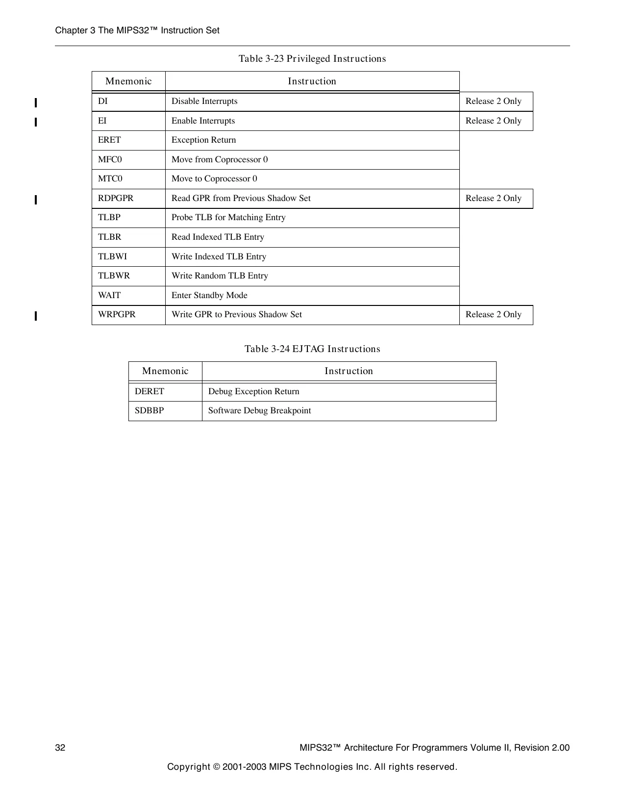
This page is a drawing, shown as the original scan.
ABS.fmt
Floating Point Absolute Value
26 25 ABS.fmt
21 20 COP1 16 15
fmt 010001 ABS fs fd 00000
Format: 11 10
000101
ABS.S fd, fs ABS.D fd, fs ABS.PS fd, fs MIPS32 MIPS32 MIPS64 MIPS32 Release 2
Purpose:
To compute the absolute value of an FP value
Description: fd ← abs(fs)
The absolute value of the value in FPR fs is placed in FPR fd. The operand and result are values in format fmt. ABS.PS takes the absolute value of the two values in FPR fs independently, and ORs together any generated exceptions.
Cause bits are ORed into the Flag bits if no exception is taken.
This operation is arithmetic; a NaN operand signals invalid operation.
Restrictions:
The fields fs and fd must specify FPRs valid for operands of type fmt. If they are not valid, the result is UNPRE- DICTABLE.
The operand must be a value in format fmt; if it is not, the result is UNPREDICTABLE and the value of the operand FPR becomes UNPREDICTABLE.
The result of ABS.PS is UNPREDICTABLE if the processor is executing in 16 FP registers mode.
Operation:
StoreFPR(fd, fmt, AbsoluteValue(ValueFPR(fs, fmt)))
Exceptions:
Coprocessor Unusable, Reserved Instruction
Floating Point Exceptions:
Unimplemented Operation, Invalid Operation
ADD
Add Word ADD
26 25 21 20 16 15 11 10
SPECIAL rs rt
Format: ADD
00000 100000 rd 000000
MIPS32 ADD rd, rs, rt
Purpose:
To add 32-bit integers. If an overflow occurs, then trap.
Description: rd ← rs + rt
The 32-bit word value in GPR rt is added to the 32-bit value in GPR rs to produce a 32-bit result.
- If the addition results in 32-bit 2’s complement arithmetic overflow, the destination register is not modified and an Integer Overflow exception occurs.
- If the addition does not overflow, the 32-bit result is placed into GPR rd.
Restrictions:
None
Operation: temp ← (GPR[rs] 31 ||GPR[rs] 31..0 ) + (GPR[rt] 31 ||GPR[rt] 31..0 )
if temp 32 ≠ temp 31 then
SignalException(IntegerOverflow) else GPR[rd] ← temp endif
Exceptions:
Integer Overflow
Programming Notes:
ADDU performs the same arithmetic operation but does not trap on overflow.
ADD.fmt
Floating Point Add ADD.fmt
26 25 21 20 16 15 11 10 COP1 ADD fmt ft fs fd 010001 000000
Format: ADD.S fd, fs, ft ADD.D fd, fs, ft ADD.PS fd, fs, ft MIPS32 MIPS32 MIPS64 MIPS32 Release 2
Purpose:
To add floating point values
Description: fd ← fs + ft
The value in FPR ft is added to the value in FPR fs. The result is calculated to infinite precision, rounded by using to the current rounding mode in FCSR, and placed into FPR fd. The operands and result are values in format fmt. ADD.PS adds the upper and lower halves of FPR fs and FPR ft independently, and ORs together any generated exceptions.
Cause bits are ORed into the Flag bits if no exception is taken.
Restrictions:
The fields fs, ft, and fd must specify FPRs valid for operands of type fmt. If they are not valid, the result is UNPRE- DICTABLE.
The operands must be values in format fmt; if they are not, the result is UNPREDICTABLE and the value of the operand FPRs becomes UNPREDICTABLE.
The result of ADD.PS is UNPREDICTABLE if the processor is executing in 16 FP registers mode.
Operation: StoreFPR (fd, fmt, ValueFPR(fs, fmt) + fmt ValueFPR(ft, fmt))
Exceptions:
Coprocessor Unusable, Reserved Instruction
Floating Point Exceptions:
Unimplemented Operation, Invalid Operation, Inexact, Overflow, Underflow
ADDI
Add Immediate Word ADDI
26 25 21 20 16 15 ADDI rs rt immediate 001000
Format: MIPS32 ADDI rt, rs, immediate
Purpose:
To add a constant to a 32-bit integer. If overflow occurs, then trap.
Description: rt ← rs + immediate
The 16-bit signed immediate is added to the 32-bit value in GPR rs to produce a 32-bit result.
- If the addition results in 32-bit 2’s complement arithmetic overflow, the destination register is not modified and an Integer Overflow exception occurs.
- If the addition does not overflow, the 32-bit result is placed into GPR rt.
Restrictions:
None
Operation: temp ← (GPR[rs] 31 ||GPR[rs] 31..0 ) + sign_extend(immediate)
if temp 32 ≠ temp 31 then
SignalException(IntegerOverflow) else GPR[rt] ← temp endif
Exceptions:
Integer Overflow
Programming Notes:
ADDIU performs the same arithmetic operation but does not trap on overflow.
ADDIU Add Immediate Unsigned Word
26 25 ADDIU
21 20 16 15 ADDIU rs rt immediate 001001
Format: ADDIU rt, rs, immediate MIPS32
Purpose:
To add a constant to a 32-bit integer
Description: rt ← rs + immediate The 16-bit signed immediate is added to the 32-bit value in GPR rs and the 32-bit arithmetic result is placed into GPR rt.
No Integer Overflow exception occurs under any circumstances.
Restrictions:
None
Operation: temp ← GPR[rs] + sign_extend(immediate) GPR[rt]← temp
Exceptions:
None
Programming Notes:
The term “unsigned” in the instruction name is a misnomer; this operation is 32-bit modulo arithmetic that does not trap on overflow. This instruction is appropriate for unsigned arithmetic, such as address arithmetic, or integer arithmetic environments that ignore overflow, such as C language arithmetic.
ADDU
Add Unsigned Word ADDU
26 25 21 20 16 15 11 10
SPECIAL rs rt
Format: ADDU
00000 100001 rd 000000
MIPS32 ADDU rd, rs, rt
Purpose:
To add 32-bit integers
Description: rd ← rs + rt
The 32-bit word value in GPR rt is added to the 32-bit value in GPR rs and the 32-bit arithmetic result is placed into GPR rd.
No Integer Overflow exception occurs under any circumstances.
Restrictions:
None
Operation: temp ← GPR[rs] + GPR[rt] GPR[rd] ← temp
Exceptions:
None
Programming Notes:
The term “unsigned” in the instruction name is a misnomer; this operation is 32-bit modulo arithmetic that does not trap on overflow. This instruction is appropriate for unsigned arithmetic, such as address arithmetic, or integer arithmetic environments that ignore overflow, such as C language arithmetic.
ALNV.PS
Floating Point Align Variable ALNV.PS
26 25 21 20 16 15 11 10
COP1X ft fs fd 010011
Format: ALNV.PS rs 011110
MIPS64 MIPS32 Release 2 ALNV.PS fd, fs, ft, rs
Purpose:
To align a misaligned pair of paired single values
Description: fd ← ByteAlign(rs 2..0 , fs, ft)
FPR fs is concatenated with FPR ft and this value is funnel-shifted by GPR rs 2..0 bytes, and written into FPR fd. If GPR rs 2..0 is 0, fd receives fs. If GPR rs 2..0 is 4, the operation depends on the current endianness.
Figure 3-1 illustrates the following example: for a big-endian operation and a byte alignment of 4, the upper half of fd receives the lower half of the paired single value in fs, and the lower half of fd receives the upper half of the paired single value in ft.
Figure 3-1 Example of an ALNV.PS Operation fs
32 31 ft
0 63
32 31 32 31
fd
The move is nonarithmetic; it causes no IEEE 754 exceptions.
Floating Point Align Variable (cont.) ALNV.PS
Restrictions:
The fields fs, ft, and fd must specify FPRs valid for operands of type PS. If they are not valid, the result is UNPRE- DICTABLE.
If GPR rs 1..0 are non-zero, the results are UNPREDICTABLE.
The result of this instruction is UNPREDICTABLE if the processor is executing in 16 FP registers mode.
Operation:
if GPR[rs] 2..0 = 0 then StoreFPR(fd, PS,ValueFPR(fs,PS)) else if GPR[rs] 2..0 ≠ 4 then UNPREDICTABLE else if BigEndianCPU then StoreFPR(fd, PS, ValueFPR(fs, PS) 31..0 || ValueFPR(ft,PS) 63..32 ) else StoreFPR(fd, PS, ValueFPR(ft, PS) 31..0 || ValueFPR(fs,PS) 63..32 ) endif
Exceptions:
Coprocessor Unusable, Reserved Instruction
Programming Notes:
ALNV.PS is designed to be used with LUXC1 to load 8 bytes of data from any 4-byte boundary. For example: /* Copy T2 bytes (a multiple of 16) of data T0 to T1, T0 unaligned, T1 aligned. Reads one dw beyond the end of T0. */ LUXC1 F0, 0(T0) /* set up by reading 1st src dw */ LI T3, 0 /* index into src and dst arrays */ ADDIU T4, T0, 8 /* base for odd dw loads */ ADDIU T5, T1, -8/* base for odd dw stores */ LOOP: LUXC1 F1, T3(T4) ALNV.PS F2, F0, F1, T0/* switch F0, F1 for little-endian */ SDC1 F2, T3(T1) ADDIU T3, T3, 16 LUXC1 F0, T3(T0) ALNV.PS F2, F1, F0, T0/* switch F1, F0 for little-endian */ BNE T3, T2, LOOP SDC1 F2, T3(T5) DONE:
Floating Point Align Variable (cont.) ALNV.PS
ALNV.PS is also useful with SUXC1 to store paired-single results in a vector loop to a possibly misaligned address:
/* T1[i] = T0[i] + F8, T0 aligned, T1 unaligned. */ CVT.PS.S F8, F8, F8/* make addend paired-single */
/* Loop header computes 1st pair into F0, stores high half if T1 */ /* misaligned */
LOOP: LDC1 ADD.PS ALNV.PS SUXC1 ADDIU LDC1 ADD.PS ALNV.PS BNE SUXC1 F2, T3(T4)/* get T0[i+2]/T0[i+3] */ F1, F2, F8/* compute T1[i+2]/T1[i+3] */ F3, F0, F1, T1/* align to dst memory */ F3, T3(T1)/* store to T1[i+0]/T1[i+1] */ T3, 16 /* i = i + 4 */ F2, T3(T0)/* get T0[i+0]/T0[i+1] */ F0, F2, F8/* compute T1[i+0]/T1[i+1] */ F3, F1, F0, T1/* align to dst memory */ T3, T2, LOOP F3, T3(T5)/* store to T1[i+2]/T1[i+3] */
/* Loop trailer stores all or half of F0, depending on T1 alignment */
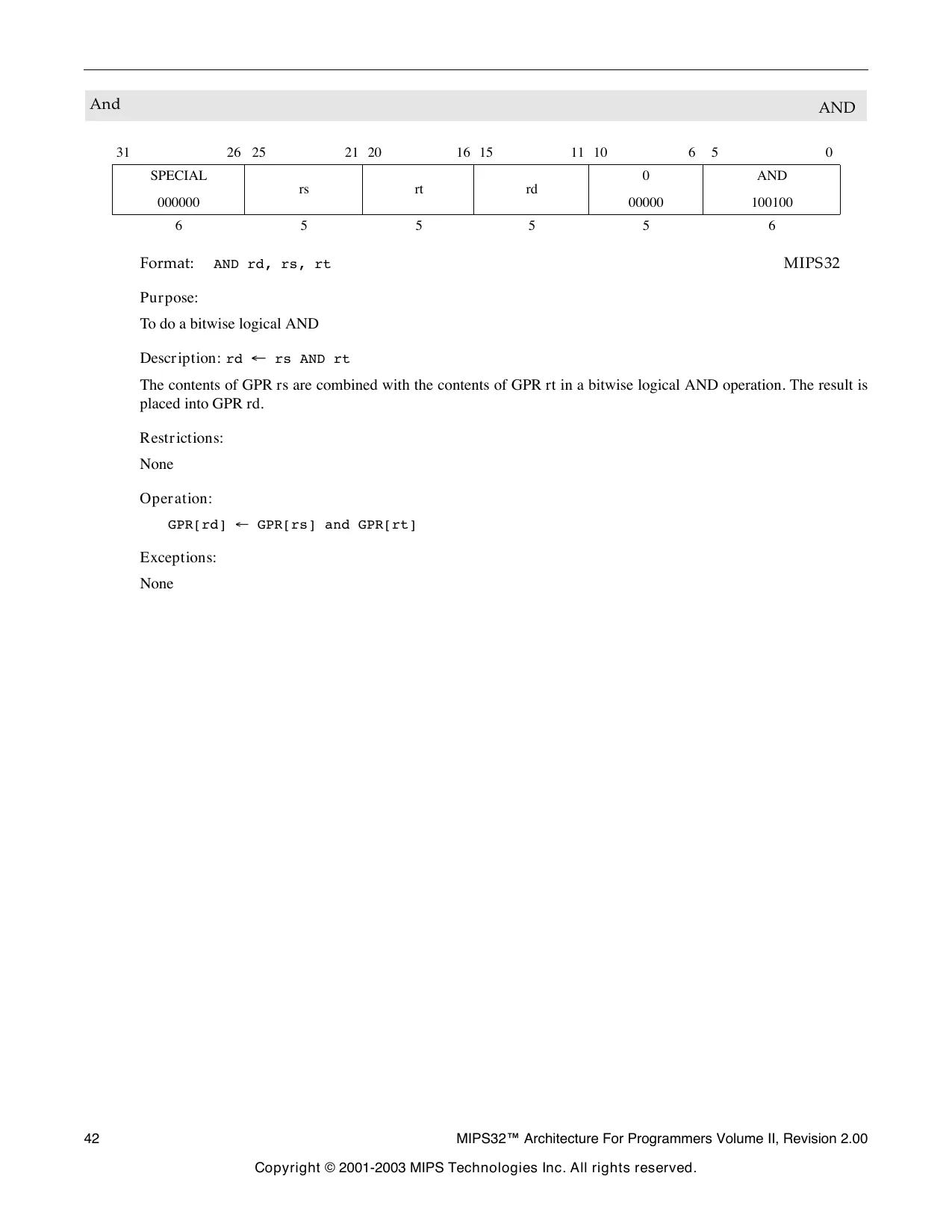
This page is a drawing, shown as the original scan.
ANDI
And Immediate ANDI
26 25 21 20 16 15 ANDI rs rt immediate 001100
Format: ANDI rt, rs, immediate MIPS32
Purpose:
To do a bitwise logical AND with a constant
Description: rt ← rs AND immediate
The 16-bit immediate is zero-extended to the left and combined with the contents of GPR rs in a bitwise logical AND operation. The result is placed into GPR rt.
Restrictions:
None
Operation: GPR[rt] ← GPR[rs] and zero_extend(immediate)
Exceptions:
None
B
Unconditional Branch B
26 25 21 20 16 15 BEQ
000100 00000 00000 offset
Format: Assembly Idiom B offset
Purpose:
To do an unconditional branch
Description: branch
B offset is the assembly idiom used to denote an unconditional branch. The actual instruction is interpreted by the hardware as BEQ r0, r0, offset.
An 18-bit signed offset (the 16-bit offset field shifted left 2 bits) is added to the address of the instruction following the branch (not the branch itself), in the branch delay slot, to form a PC-relative effective target address.
Restrictions:
Processor operation is UNPREDICTABLE if a branch, jump, ERET, DERET, or WAIT instruction is placed in the delay slot of a branch or jump.
Operation:
I: I+1: target_offset ← sign_extend(offset || 0 2 ) PC ← PC + target_offset
Exceptions:
None
Programming Notes: With the 18-bit signed instruction offset, the conditional branch range is ± 128 Kbytes. Use jump (J) or jump register (JR) instructions to branch to addresses outside this range.
BAL
Branch and Link BAL
26 25 21 20 16 15 REGIMM BGEZAL
000001 00000 10001 offset
Format: BAL rs, offset Assembly Idiom
Purpose:
To do an unconditional PC-relative procedure call
Description: procedure_call
BAL offset is the assembly idiom used to denote an unconditional branch. The actual instruction is iterpreted by the hardware as BGEZAL r0, offset.
Place the return address link in GPR 31. The return link is the address of the second instruction following the branch, where execution continues after a procedure call.
An 18-bit signed offset (the 16-bit offset field shifted left 2 bits) is added to the address of the instruction following the branch (not the branch itself), in the branch delay slot, to form a PC-relative effective target address.
Restrictions:
Processor operation is UNPREDICTABLE if a branch, jump, ERET, DERET, or WAIT instruction is placed in the delay slot of a branch or jump.
GPR 31 must not be used for the source register rs, because such an instruction does not have the same effect when reexecuted. The result of executing such an instruction is UNPREDICTABLE. This restriction permits an exception handler to resume execution by reexecuting the branch when an exception occurs in the branch delay slot.
Operation:
I:
I+1: target_offset ← sign_extend(offset || 0 2 ) GPR[31] ← PC + 8 PC ← PC + target_offset
Exceptions:
None
Programming Notes: With the 18-bit signed instruction offset, the conditional branch range is ± 128 KBytes. Use jump and link (JAL) or jump and link register (JALR) instructions for procedure calls to addresses outside this range.
BC1F
Branch on FP False BC1F
26 25 21 20
COP1 BC
010001 01000 18 17 16 15
cc
Format: BC1F BC1F nd tf offset
offset (cc = 0 implied) cc, offset MIPS32 MIPS32
Purpose:
To test an FP condition code and do a PC-relative conditional branch
Description: if cc = 0 then branch
An 18-bit signed offset (the 16-bit offset field shifted left 2 bits) is added to the address of the instruction following the branch (not the branch itself) in the branch delay slot to form a PC-relative effective target address. If the FP condition code bit CC is false (0), the program branches to the effective target address after the instruction in the delay slot is executed. An FP condition code is set by the FP compare instruction, C.cond.fmt.
Restrictions:
Processor operation is UNPREDICTABLE if a branch, jump, ERET, DERET, or WAIT instruction is placed in the delay slot of a branch or jump.
Operation:
This operation specification is for the general Branch On Condition operation with the tf (true/false) and nd (nullify delay slot) fields as variables. The individual instructions BC1F, BC1FL, BC1T, and BC1TL have specific values for tf and nd. I:
I+1: condition ← FPConditionCode(cc) = 0 target_offset ← (offset 15 ) GPRLEN-(16+2) || offset || 0 2 if condition then PC ← PC + target_offset endif
Branch on FP False (cont.) BC1F
Exceptions:
Coprocessor Unusable, Reserved Instruction
Floating Point Exceptions:
Unimplemented Operation
Programming Notes: With the 18-bit signed instruction offset, the conditional branch range is ± 128 KBytes. Use jump (J) or jump register (JR) instructions to branch to addresses outside this range
Historical Information:
The MIPS I architecture defines a single floating point condition code, implemented as the coprocessor 1 condition signal (Cp1Cond) and the C bit in the FP Control/Status register. MIPS I, II, and III architectures must have the CC field set to 0, which is implied by the first format in the “Format” section.
The MIPS IV and MIPS32 architectures add seven more Condition Code bits to the original condition code 0. FP compare and conditional branch instructions specify the Condition Code bit to set or test. Both assembler formats are valid for MIPS IV and MIPS32.
In the MIPS I, II, and III architectures there must be at least one instruction between the compare instruction that sets the condition code and the branch instruction that tests it. Hardware does not detect a violation of this restriction.
BC1FL
Branch on FP False Likely BC1FL
26 25 21 20
COP1 BC
010001 01000 18 17 16 15
cc
Format: BC1FL BC1FL nd tf offset
offset (cc = 0 implied) cc, offset MIPS32 MIPS32
Purpose:
To test an FP condition code and make a PC-relative conditional branch; execute the instruction in the delay slot only if the branch is taken.
Description: if cc = 0 then branch_likely
An 18-bit signed offset (the 16-bit offset field shifted left 2 bits) is added to the address of the instruction following the branch (not the branch itself) in the branch delay slot to form a PC-relative effective target address. If the FP Condition Code bit CC is false (0), the program branches to the effective target address after the instruction in the delay slot is executed. If the branch is not taken, the instruction in the delay slot is not executed.
An FP condition code is set by the FP compare instruction, C.cond.fmt.
Restrictions:
Processor operation is UNPREDICTABLE if a branch, jump, ERET, DERET, or WAIT instruction is placed in the delay slot of a branch or jump.
Operation:
This operation specification is for the general Branch On Condition operation with the tf (true/false) and nd (nullify delay slot) fields as variables. The individual instructions BC1F, BC1FL, BC1T, and BC1TL have specific values for tf and nd. I:
I+1: condition ← FPConditionCode(cc) = 0 target_offset ← (offset 15 ) GPRLEN-(16+2) || offset || 0 2 if condition then PC ← PC + target_offset else NullifyCurrentInstruction() endif
Branch on FP False Likely (cont.) BC1FL
Exceptions:
Coprocessor Unusable, Reserved Instruction
Floating Point Exceptions:
Unimplemented Operation
Programming Notes: With the 18-bit signed instruction offset, the conditional branch range is ± 128 KBytes. Use jump (J) or jump register (JR) instructions to branch to addresses outside this range.
Software is strongly encouraged to avoid the use of the Branch Likely instructions, as they will be removed from a future revision of the MIPS Architecture.
Some implementations always predict the branch will be taken, so there is a significant penalty if the branch is not taken. Software should only use this instruction when there is a very high probability (98% or more) that the branch will be taken. If the branch is not likely to be taken or if the probability of a taken branch is unknown, software is encouraged to use the BC1F instruction instead.
Historical Information:
The MIPS I architecture defines a single floating point condition code, implemented as the coprocessor 1 condition signal (Cp1Cond) and the C bit in the FP Control/Status register. MIPS I, II, and III architectures must have the CC field set to 0, which is implied by the first format in the “Format” section.
The MIPS IV and MIPS32 architectures add seven more Condition Code bits to the original condition code 0. FP compare and conditional branch instructions specify the Condition Code bit to set or test. Both assembler formats are valid for MIPS IV and MIPS32.
In the MIPS II andIII architectionrs there must be at least one instruction between the compare instruction that sets a condition code and the branch instruction that tests it. Hardware does not detect a violation of this restriction.
BC1T
Branch on FP True BC1T
26 25 21 20
COP1 BC
010001 01000 18 17 16 15
cc
Format: nd tf offset
MIPS32 MIPS32 BC1T offset (cc = 0 implied) BC1T cc, offset
Purpose:
To test an FP condition code and do a PC-relative conditional branch
Description: if cc = 1 then branch
An 18-bit signed offset (the 16-bit offset field shifted left 2 bits) is added to the address of the instruction following the branch (not the branch itself) in the branch delay slot to form a PC-relative effective target address. If the FP condition code bit CC is true (1), the program branches to the effective target address after the instruction in the delay slot is executed. An FP condition code is set by the FP compare instruction, C.cond.fmt.
Restrictions:
Processor operation is UNPREDICTABLE if a branch, jump, ERET, DERET, or WAIT instruction is placed in the delay slot of a branch or jump.
Operation:
This operation specification is for the general Branch On Condition operation with the tf (true/false) and nd (nullify delay slot) fields as variables. The individual instructions BC1F, BC1FL, BC1T, and BC1TL have specific values for tf and nd. I:
I+1: condition ← FPConditionCode(cc) = 1 target_offset ← (offset 15 ) GPRLEN-(16+2) || offset || 0 2 if condition then PC ← PC + target_offset endif
Branch on FP True (cont.) BC1T
Exceptions:
Coprocessor Unusable, Reserved Instruction
Floating Point Exceptions:
Unimplemented Operation
Programming Notes: With the 18-bit signed instruction offset, the conditional branch range is ± 128 KBytes. Use jump (J) or jump register (JR) instructions to branch to addresses outside this range.
Historical Information:
The MIPS I architecture defines a single floating point condition code, implemented as the coprocessor 1 condition signal (Cp1Cond) and the C bit in the FP Control/Status register. MIPS I, II, and III architectures must have the CC field set to 0, which is implied by the first format in the “Format” section.
The MIPS IV and MIPS32 architectures add seven more Condition Code bits to the original condition code 0. FP compare and conditional branch instructions specify the Condition Code bit to set or test. Both assembler formats are valid for MIPS IV and MIPS32.
In the MIPS I, II, and III architectures there must be at least one instruction between the compare instruction that sets the condition code and the branch instruction that tests it. Hardware does not detect a violation of this restriction.
BC1TL
Branch on FP True Likely BC1TL
26 25 21 20
COP1 BC
010001 01000 18 17 16 15
cc
Format: BC1TL BC1TL nd tf offset
offset (cc = 0 implied) cc, offset MIPS32 MIPS32
Purpose:
To test an FP condition code and do a PC-relative conditional branch; execute the instruction in the delay slot only if the branch is taken.
Description: if cc = 1 then branch_likely
An 18-bit signed offset (the 16-bit offset field shifted left 2 bits) is added to the address of the instruction following the branch (not the branch itself) in the branch delay slot to form a PC-relative effective target address. If the FP Condition Code bit CC is true (1), the program branches to the effective target address after the instruction in the delay slot is executed. If the branch is not taken, the instruction in the delay slot is not executed.
An FP condition code is set by the FP compare instruction, C.cond.fmt.
Restrictions:
Processor operation is UNPREDICTABLE if a branch, jump, ERET, DERET, or WAIT instruction is placed in the delay slot of a branch or jump.
Operation:
This operation specification is for the general Branch On Condition operation with the tf (true/false) and nd (nullify delay slot) fields as variables. The individual instructions BC1F, BC1FL, BC1T, and BC1TL have specific values for tf and nd. I:
I+1: condition ← FPConditionCode(cc) = 1 target_offset ← (offset 15 ) GPRLEN-(16+2) || offset || 0 2 if condition then PC ← PC + target_offset else NullifyCurrentInstruction() endif
Branch on FP True Likely (cont.) BC1TL
Exceptions:
Coprocessor Unusable, Reserved Instruction
Floating Point Exceptions:
Unimplemented Operation
Programming Notes: With the 18-bit signed instruction offset, the conditional branch range is ± 128 KBytes. Use jump (J) or jump register (JR) instructions to branch to addresses outside this range.
Software is strongly encouraged to avoid the use of the Branch Likely instructions, as they will be removed from a future revision of the MIPS Architecture.
Some implementations always predict the branch will be taken, so there is a significant penalty if the branch is not taken. Software should only use this instruction when there is a very high probability (98% or more) that the branch will be taken. If the branch is not likely to be taken or if the probability of a taken branch is unknown, software is encouraged to use the BC1T instruction instead.
Historical Information:
The MIPS I architecture defines a single floating point condition code, implemented as the coprocessor 1 condition signal (Cp1Cond) and the C bit in the FP Control/Status register. MIPS I, II, and III architectures must have the CC field set to 0, which is implied by the first format in the “Format” section.
The MIPS IV and MIPS32 architectures add seven more Condition Code bits to the original condition code 0. FP compare and conditional branch instructions specify the Condition Code bit to set or test. Both assembler formats are valid for MIPS IV and MIPS32.
In the MIPS II andIII architectionrs there must be at least one instruction between the compare instruction that sets a condition code and the branch instruction that tests it. Hardware does not detect a violation of this restriction.
BC2F
Branch on COP2 False BC2F
26 25 21 20 COP2 18 17 16 15 BC nd tf cc 010010 01000
Format: BC2F BC2F offset
offset (cc = 0 implied) cc, offset MIPS32 MIPS32
Purpose:
To test a COP2 condition code and do a PC-relative conditional branch
Description: if cc = 0 then branch
An 18-bit signed offset (the 16-bit offset field shifted left 2 bits) is added to the address of the instruction following the branch (not the branch itself) in the branch delay slot to form a PC-relative effective target address. If the COP2 condition specified by CC is false (0), the program branches to the effective target address after the instruction in the delay slot is executed.
Restrictions:
Processor operation is UNPREDICTABLE if a branch, jump, ERET, DERET, or WAIT instruction is placed in the delay slot of a branch or jump.
Operation:
This operation specification is for the general Branch On Condition operation with the tf (true/false) and nd (nullify delay slot) fields as variables. The individual instructions BC2F, BC2FL, BC2T, and BC2TL have specific values for tf and nd. I:
I+1: condition ← COP2Condition(cc) = 0 target_offset ← (offset 15 ) GPRLEN-(16+2) || offset || 0 2 if condition then PC ← PC + target_offset endif
Exceptions:
Coprocessor Unusable, Reserved Instruction
Programming Notes: With the 18-bit signed instruction offset, the conditional branch range is ± 128 KBytes. Use jump (J) or jump register (JR) instructions to branch to addresses outside this range.
BC2FL
Branch on COP2 False Likely BC2FL
26 25 21 20
COP2 BC
010010 01000 18 17 16 15
cc
Format: BC2FL BC2FL nd tf offset
offset (cc = 0 implied) cc, offset MIPS32 MIPS32
Purpose:
To test a COP2 condition code and make a PC-relative conditional branch; execute the instruction in the delay slot only if the branch is taken.
Description: if cc = 0 then branch_likely
An 18-bit signed offset (the 16-bit offset field shifted left 2 bits) is added to the address of the instruction following the branch (not the branch itself) in the branch delay slot to form a PC-relative effective target address. If the COP2 condition specified by CC is false (0), the program branches to the effective target address after the instruction in the delay slot is executed. If the branch is not taken, the instruction in the delay slot is not executed.
Restrictions:
Processor operation is UNPREDICTABLE if a branch, jump, ERET, DERET, or WAIT instruction is placed in the delay slot of a branch or jump.
Operation:
This operation specification is for the general Branch On Condition operation with the tf (true/false) and nd (nullify delay slot) fields as variables. The individual instructions BC2F, BC2FL, BC2T, and BC2TL have specific values for tf and nd. I:
I+1: condition ← COP2Condition(cc) = 0 target_offset ← (offset 15 ) GPRLEN-(16+2) || offset || 0 2 if condition then PC ← PC + target_offset else NullifyCurrentInstruction() endif
Branch on COP2 False Likely (cont.) BC2FL
Exceptions:
Coprocessor Unusable, Reserved Instruction
Programming Notes: With the 18-bit signed instruction offset, the conditional branch range is ± 128 KBytes. Use jump (J) or jump register (JR) instructions to branch to addresses outside this range.
Software is strongly encouraged to avoid the use of the Branch Likely instructions, as they will be removed from a future revision of the MIPS Architecture.
Some implementations always predict the branch will be taken, so there is a significant penalty if the branch is not taken. Software should only use this instruction when there is a very high probability (98% or more) that the branch will be taken. If the branch is not likely to be taken or if the probability of a taken branch is unknown, software is encouraged to use the BC2F instruction instead.
BC2T
Branch on COP2 True BC2T
26 25 COP2 21 20 18 17 16 15 BC nd tf cc 010010 01000
Format: offset
BC2T offset (cc = 0 implied) BC2T cc, offset MIPS32 MIPS32
Purpose:
To test a COP2 condition code and do a PC-relative conditional branch
Description: if cc = 1 then branch
An 18-bit signed offset (the 16-bit offset field shifted left 2 bits) is added to the address of the instruction following the branch (not the branch itself) in the branch delay slot to form a PC-relative effective target address. If the COP2 condition specified by CC is true (1), the program branches to the effective target address after the instruction in the delay slot is executed.
Restrictions:
Processor operation is UNPREDICTABLE if a branch, jump, ERET, DERET, or WAIT instruction is placed in the delay slot of a branch or jump.
Operation:
This operation specification is for the general Branch On Condition operation with the tf (true/false) and nd (nullify delay slot) fields as variables. The individual instructions BC2F, BC2FL, BC2T, and BC2TL have specific values for tf and nd. I:
I+1: condition ← COP2Condition(cc) = 1 target_offset ← (offset 15 ) GPRLEN-(16+2) || offset || 0 2 if condition then PC ← PC + target_offset endif
Exceptions:
Coprocessor Unusable, Reserved Instruction
Programming Notes: With the 18-bit signed instruction offset, the conditional branch range is ± 128 KBytes. Use jump (J) or jump register (JR) instructions to branch to addresses outside this range.
BC2TL
Branch on COP2 True Likely BC2TL
26 25 21 20
COP2 BC
010010 01000 18 17 16 15
cc
Format: BC2TL BC2TL nd tf offset
offset (cc = 0 implied) cc, offset MIPS32 MIPS32
Purpose:
To test a COP2 condition code and do a PC-relative conditional branch; execute the instruction in the delay slot only if the branch is taken.
Description: if cc = 1 then branch_likely
An 18-bit signed offset (the 16-bit offset field shifted left 2 bits) is added to the address of the instruction following the branch (not the branch itself) in the branch delay slot to form a PC-relative effective target address. If the COP2 condition specified by CC is true (1), the program branches to the effective target address after the instruction in the delay slot is executed. If the branch is not taken, the instruction in the delay slot is not executed.
Restrictions:
Processor operation is UNPREDICTABLE if a branch, jump, ERET, DERET, or WAIT instruction is placed in the delay slot of a branch or jump.
Operation:
This operation specification is for the general Branch On Condition operation with the tf (true/false) and nd (nullify delay slot) fields as variables. The individual instructions BC2F, BC2FL, BC2T, and BC2TL have specific values for tf and nd. I:
I+1: condition ← COP2Condition(cc) = 1 target_offset ← (offset 15 ) GPRLEN-(16+2) || offset || 0 2 if condition then PC ← PC + target_offset else NullifyCurrentInstruction() endif
Branch on COP2 True Likely (cont.) BC2TL
Exceptions:
Coprocessor Unusable, Reserved Instruction
Programming Notes: With the 18-bit signed instruction offset, the conditional branch range is ± 128 KBytes. Use jump (J) or jump register (JR) instructions to branch to addresses outside this range.
Software is strongly encouraged to avoid the use of the Branch Likely instructions, as they will be removed from a future revision of the MIPS Architecture.
Some implementations always predict the branch will be taken, so there is a significant penalty if the branch is not taken. Software should only use this instruction when there is a very high probability (98% or more) that the branch will be taken. If the branch is not likely to be taken or if the probability of a taken branch is unknown, software is encouraged to use the BC2T instruction instead.
BEQ Branch on Equal BEQ
26 25 21 20 16 15 BEQ rs rt offset 000100
Format: MIPS32 BEQ rs, rt, offset
Purpose:
To compare GPRs then do a PC-relative conditional branch
Description: if rs = rt then branch
An 18-bit signed offset (the 16-bit offset field shifted left 2 bits) is added to the address of the instruction following the branch (not the branch itself), in the branch delay slot, to form a PC-relative effective target address.
If the contents of GPR rs and GPR rt are equal, branch to the effective target address after the instruction in the delay slot is executed.
Restrictions:
Processor operation is UNPREDICTABLE if a branch, jump, ERET, DERET, or WAIT instruction is placed in the delay slot of a branch or jump.
Operation:
I:
I+1: target_offset ← sign_extend(offset || 0 2 ) condition ← (GPR[rs] = GPR[rt]) if condition then PC ← PC + target_offset endif
Exceptions:
None
Programming Notes: With the 18-bit signed instruction offset, the conditional branch range is ± 128 Kbytes. Use jump (J) or jump register (JR) instructions to branch to addresses outside this range.
BEQ r0, r0 offset, expressed as B offset, is the assembly idiom used to denote an unconditional branch.
BEQL
Branch on Equal Likely BEQL
26 25 21 20 16 15 BEQL rs rt offset 010100
Format: BEQL rs, rt, offset MIPS32
Purpose:
To compare GPRs then do a PC-relative conditional branch; execute the delay slot only if the branch is taken.
Description: if rs = rt then branch_likely
An 18-bit signed offset (the 16-bit offset field shifted left 2 bits) is added to the address of the instruction following the branch (not the branch itself), in the branch delay slot, to form a PC-relative effective target address.
If the contents of GPR rs and GPR rt are equal, branch to the target address after the instruction in the delay slot is executed. If the branch is not taken, the instruction in the delay slot is not executed.
Restrictions:
Processor operation is UNPREDICTABLE if a branch, jump, ERET, DERET, or WAIT instruction is placed in the delay slot of a branch or jump.
Operation:
I:
I+1: target_offset ← sign_extend(offset || 0 2 ) condition ← (GPR[rs] = GPR[rt]) if condition then PC ← PC + target_offset else NullifyCurrentInstruction() endif
Exceptions:
None
Branch on Equal Likely (cont.) BEQL
Programming Notes: With the 18-bit signed instruction offset, the conditional branch range is ± 128 KBytes. Use jump (J) or jump register (JR) instructions to branch to addresses outside this range.
Software is strongly encouraged to avoid the use of the Branch Likely instructions, as they will be removed from a future revision of the MIPS Architecture.
Some implementations always predict the branch will be taken, so there is a significant penalty if the branch is not taken. Software should only use this instruction when there is a very high probability (98% or more) that the branch will be taken. If the branch is not likely to be taken or if the probability of a taken branch is unknown, software is encouraged to use the BEQ instruction instead.
Historical Information:
In the MIPS I architecture, this instruction signaled a Reserved Instruction Exception.
BGEZ
Branch on Greater Than or Equal to Zero
26 25 BGEZ
21 20 REGIMM 16 15 BGEZ rs 000001 offset 00001
Format: BGEZ rs, offset MIPS32
Purpose:
To test a GPR then do a PC-relative conditional branch
Description: if rs ≥ 0 then branch
An 18-bit signed offset (the 16-bit offset field shifted left 2 bits) is added to the address of the instruction following the branch (not the branch itself), in the branch delay slot, to form a PC-relative effective target address.
If the contents of GPR rs are greater than or equal to zero (sign bit is 0), branch to the effective target address after the instruction in the delay slot is executed.
Restrictions:
Processor operation is UNPREDICTABLE if a branch, jump, ERET, DERET, or WAIT instruction is placed in the delay slot of a branch or jump.
Operation:
I:
I+1: target_offset ← sign_extend(offset || 0 2 ) condition ← GPR[rs] ≥ 0 GPRLEN if condition then PC ← PC + target_offset endif
Exceptions:
None
Programming Notes: With the 18-bit signed instruction offset, the conditional branch range is ± 128 KBytes. Use jump (J) or jump register (JR) instructions to branch to addresses outside this range.
BGEZAL
Branch on Greater Than or Equal to Zero and Link
26 25 21 20 REGIMM BGEZAL
16 15 BGEZAL rs 000001 offset 10001
Format: MIPS32 BGEZAL rs, offset
Purpose:
To test a GPR then do a PC-relative conditional procedure call
Description: if rs ≥ 0 then procedure_call Place the return address link in GPR 31. The return link is the address of the second instruction following the branch, where execution continues after a procedure call.
An 18-bit signed offset (the 16-bit offset field shifted left 2 bits) is added to the address of the instruction following the branch (not the branch itself), in the branch delay slot, to form a PC-relative effective target address.
If the contents of GPR rs are greater than or equal to zero (sign bit is 0), branch to the effective target address after the instruction in the delay slot is executed.
Restrictions:
Processor operation is UNPREDICTABLE if a branch, jump, ERET, DERET, or WAIT instruction is placed in the delay slot of a branch or jump.
GPR 31 must not be used for the source register rs, because such an instruction does not have the same effect when reexecuted. The result of executing such an instruction is UNPREDICTABLE. This restriction permits an exception handler to resume execution by reexecuting the branch when an exception occurs in the branch delay slot.
Operation:
I:
I+1: target_offset ← sign_extend(offset || 0 2 ) condition ← GPR[rs] ≥ 0 GPRLEN GPR[31] ← PC + 8 if condition then PC ← PC + target_offset endif
Exceptions:
None
Programming Notes: With the 18-bit signed instruction offset, the conditional branch range is ± 128 KBytes. Use jump and link (JAL) or jump and link register (JALR) instructions for procedure calls to addresses outside this range.
BGEZAL r0, offset, expressed as BAL offset, is the assembly idiom used to denote a PC-relative branch and link. BAL is used in a manner similar to JAL, but provides PC-relative addressing and a more limited target PC range.
BGEZALL
Branch on Greater Than or Equal to Zero and Link Likely
26 25 21 20 REGIMM 16 15 BGEZALL rs 000001 offset 10011
Format: BGEZALL
BGEZALL rs, offset MIPS32
Purpose:
To test a GPR then do a PC-relative conditional procedure call; execute the delay slot only if the branch is taken.
Description: if rs ≥ 0 then procedure_call_likely Place the return address link in GPR 31. The return link is the address of the second instruction following the branch, where execution continues after a procedure call.
An 18-bit signed offset (the 16-bit offset field shifted left 2 bits) is added to the address of the instruction following the branch (not the branch itself), in the branch delay slot, to form a PC-relative effective target address.
If the contents of GPR rs are greater than or equal to zero (sign bit is 0), branch to the effective target address after the instruction in the delay slot is executed. If the branch is not taken, the instruction in the delay slot is not executed.
Restrictions:
GPR 31 must not be used for the source register rs, because such an instruction does not have the same effect when reexecuted. The result of executing such an instruction is UNPREDICTABLE. This restriction permits an exception handler to resume execution by reexecuting the branch when an exception occurs in the branch delay slot.
Processor operation is UNPREDICTABLE if a branch, jump, ERET, DERET, or WAIT instruction is placed in the delay slot of a branch or jump.
Operation:
I:
I+1: target_offset ← sign_extend(offset || 0 2 ) condition ← GPR[rs] ≥ 0 GPRLEN GPR[31] ← PC + 8 if condition then PC ← PC + target_offset else NullifyCurrentInstruction() endif
Exceptions:
None
Branch on Greater Than or Equal to Zero and Link Likely (con’t.) BGEZALL
Programming Notes: With the 18-bit signed instruction offset, the conditional branch range is ± 128 KBytes. Use jump and link (JAL) or jump and link register (JALR) instructions for procedure calls to addresses outside this range.
Software is strongly encouraged to avoid the use of the Branch Likely instructions, as they will be removed from a future revision of the MIPS Architecture.
Some implementations always predict the branch will be taken, so there is a significant penalty if the branch is not taken. Software should only use this instruction when there is a very high probability (98% or more) that the branch will be taken. If the branch is not likely to be taken or if the probability of a taken branch is unknown, software is encouraged to use the BGEZAL instruction instead.
Historical Information:
In the MIPS I architecture, this instruction signaled a Reserved Instruction Exception.
BGEZL
Branch on Greater Than or Equal to Zero Likely
26 25 21 20 REGIMM BGEZL
16 15 BGEZL rs 000001 offset 00011
Format: BGEZL rs, offset MIPS32
Purpose:
To test a GPR then do a PC-relative conditional branch; execute the delay slot only if the branch is taken.
Description: if rs ≥ 0 then branch_likely
An 18-bit signed offset (the 16-bit offset field shifted left 2 bits) is added to the address of the instruction following the branch (not the branch itself), in the branch delay slot, to form a PC-relative effective target address.
If the contents of GPR rs are greater than or equal to zero (sign bit is 0), branch to the effective target address after the instruction in the delay slot is executed. If the branch is not taken, the instruction in the delay slot is not executed.
Restrictions:
Processor operation is UNPREDICTABLE if a branch, jump, ERET, DERET, or WAIT instruction is placed in the delay slot of a branch or jump.
Operation:
I:
I+1: target_offset ← sign_extend(offset || 0 2 ) condition ← GPR[rs] ≥ 0 GPRLEN if condition then PC ← PC + target_offset else NullifyCurrentInstruction() endif
Exceptions:
None
Branch on Greater Than or Equal to Zero Likely (cont.) BGEZL
Programming Notes: With the 18-bit signed instruction offset, the conditional branch range is ± 128 KBytes. Use jump (J) or jump register (JR) instructions to branch to addresses outside this range.
Software is strongly encouraged to avoid the use of the Branch Likely instructions, as they will be removed from a future revision of the MIPS Architecture.
Some implementations always predict the branch will be taken, so there is a significant penalty if the branch is not taken. Software should only use this instruction when there is a very high probability (98% or more) that the branch will be taken. If the branch is not likely to be taken or if the probability of a taken branch is unknown, software is encouraged to use the BGEZ instruction instead.
Historical Information:
In the MIPS I architecture, this instruction signaled a Reserved Instruction Exception.
BGTZ
Branch on Greater Than Zero BGTZ
26 25 21 20 16 15 BGTZ rs 000111 offset 00000
Format: BGTZ rs, offset MIPS32
Purpose:
To test a GPR then do a PC-relative conditional branch
Description: if rs > 0 then branch
An 18-bit signed offset (the 16-bit offset field shifted left 2 bits) is added to the address of the instruction following the branch (not the branch itself), in the branch delay slot, to form a PC-relative effective target address.
If the contents of GPR rs are greater than zero (sign bit is 0 but value not zero), branch to the effective target address after the instruction in the delay slot is executed.
Restrictions:
Processor operation is UNPREDICTABLE if a branch, jump, ERET, DERET, or WAIT instruction is placed in the delay slot of a branch or jump.
Operation:
I:
I+1: target_offset ← sign_extend(offset || 0 2 ) condition ← GPR[rs] > 0 GPRLEN if condition then PC ← PC + target_offset endif
Exceptions:
None
Programming Notes: With the 18-bit signed instruction offset, the conditional branch range is ± 128 KBytes. Use jump (J) or jump register (JR) instructions to branch to addresses outside this range.
BGTZL
Branch on Greater Than Zero Likely
26 25 BGTZL
21 20 BGTZL 16 15
rs 010111 offset 00000
Format: MIPS32 BGTZL rs, offset
Purpose:
To test a GPR then do a PC-relative conditional branch; execute the delay slot only if the branch is taken.
Description: if rs > 0 then branch_likely
An 18-bit signed offset (the 16-bit offset field shifted left 2 bits) is added to the address of the instruction following the branch (not the branch itself), in the branch delay slot, to form a PC-relative effective target address.
If the contents of GPR rs are greater than zero (sign bit is 0 but value not zero), branch to the effective target address after the instruction in the delay slot is executed. If the branch is not taken, the instruction in the delay slot is not executed.
Restrictions:
Processor operation is UNPREDICTABLE if a branch, jump, ERET, DERET, or WAIT instruction is placed in the delay slot of a branch or jump.
Operation:
I:
I+1: target_offset ← sign_extend(offset || 0 2 ) condition ← GPR[rs] > 0 GPRLEN if condition then PC ← PC + target_offset else NullifyCurrentInstruction() endif
Exceptions:
None
Branch on Greater Than Zero Likely (cont.) BGTZL
Programming Notes: With the 18-bit signed instruction offset, the conditional branch range is ± 128 KBytes. Use jump (J) or jump register (JR) instructions to branch to addresses outside this range.
Software is strongly encouraged to avoid the use of the Branch Likely instructions, as they will be removed from a future revision of the MIPS Architecture.
Some implementations always predict the branch will be taken, so there is a significant penalty if the branch is not taken. Software should only use this instruction when there is a very high probability (98% or more) that the branch will be taken. If the branch is not likely to be taken or if the probability of a taken branch is unknown, software is encouraged to use the BGTZ instruction instead.
Historical Information:
In the MIPS I architecture, this instruction signaled a Reserved Instruction Exception.
BLEZ
Branch on Less Than or Equal to Zero
26 25 BLEZ
21 20 16 15 BLEZ rs 000110 offset 00000
Format: MIPS32 BLEZ rs, offset
Purpose:
To test a GPR then do a PC-relative conditional branch
Description: if rs ≤ 0 then branch
An 18-bit signed offset (the 16-bit offset field shifted left 2 bits) is added to the address of the instruction following the branch (not the branch itself), in the branch delay slot, to form a PC-relative effective target address.
If the contents of GPR rs are less than or equal to zero (sign bit is 1 or value is zero), branch to the effective target address after the instruction in the delay slot is executed.
Restrictions:
Processor operation is UNPREDICTABLE if a branch, jump, ERET, DERET, or WAIT instruction is placed in the delay slot of a branch or jump.
Operation:
I:
I+1: target_offset ← sign_extend(offset || 0 2 ) condition ← GPR[rs] ≤ 0 GPRLEN if condition then PC ← PC + target_offset endif
Exceptions:
None
Programming Notes: With the 18-bit signed instruction offset, the conditional branch range is ± 128 KBytes. Use jump (J) or jump register (JR) instructions to branch to addresses outside this range.
BLEZL
Branch on Less Than or Equal to Zero Likely
26 25 BLEZL
21 20 BLEZL 16 15
rs 010110 offset 00000
Format: BLEZL rs, offset MIPS32
Purpose:
To test a GPR then do a PC-relative conditional branch; execute the delay slot only if the branch is taken.
Description: if rs ≤ 0 then branch_likely
An 18-bit signed offset (the 16-bit offset field shifted left 2 bits) is added to the address of the instruction following the branch (not the branch itself), in the branch delay slot, to form a PC-relative effective target address.
If the contents of GPR rs are less than or equal to zero (sign bit is 1 or value is zero), branch to the effective target address after the instruction in the delay slot is executed. If the branch is not taken, the instruction in the delay slot is not executed.
Restrictions:
Processor operation is UNPREDICTABLE if a branch, jump, ERET, DERET, or WAIT instruction is placed in the delay slot of a branch or jump.
Operation:
I:
I+1: target_offset ← sign_extend(offset || 0 2 ) condition ← GPR[rs] ≤ 0 GPRLEN if condition then PC ← PC + target_offset else NullifyCurrentInstruction() endif
Exceptions:
None
Branch on Less Than or Equal to Zero Likely (cont.) BLEZL
Programming Notes: With the 18-bit signed instruction offset, the conditional branch range is ± 128 KBytes. Use jump (J) or jump register (JR) instructions to branch to addresses outside this range.
Software is strongly encouraged to avoid the use of the Branch Likely instructions, as they will be removed from a future revision of the MIPS Architecture.
Some implementations always predict the branch will be taken, so there is a significant penalty if the branch is not taken. Software should only use this instruction when there is a very high probability (98% or more) that the branch will be taken. If the branch is not likely to be taken or if the probability of a taken branch is unknown, software is encouraged to use the BLEZ instruction instead.
Historical Information:
In the MIPS I architecture, this instruction signaled a Reserved Instruction Exception.
BLTZ
Branch on Less Than Zero BLTZ
26 25 21 20 REGIMM 16 15 BLTZ rs 000001 offset 00000
Format: BLTZ rs, offset MIPS32
Purpose:
To test a GPR then do a PC-relative conditional branch
Description: if rs < 0 then branch
An 18-bit signed offset (the 16-bit offset field shifted left 2 bits) is added to the address of the instruction following the branch (not the branch itself), in the branch delay slot, to form a PC-relative effective target address.
If the contents of GPR rs are less than zero (sign bit is 1), branch to the effective target address after the instruction in the delay slot is executed.
Restrictions:
Processor operation is UNPREDICTABLE if a branch, jump, ERET, DERET, or WAIT instruction is placed in the delay slot of a branch or jump.
Operation: I:
I+1: target_offset ← sign_extend(offset || 0 2 ) condition ← GPR[rs] < 0 GPRLEN if condition then PC ← PC + target_offset endif
Exceptions:
None
Programming Notes: With the 18-bit signed instruction offset, the conditional branch range is ± 128 KBytes. Use jump and link (JAL) or jump and link register (JALR) instructions for procedure calls to addresses outside this range.
BLTZAL Branch on Less Than Zero and Link
26 25 BLTZAL
21 20 REGIMM 16 15 BLTZAL rs 000001 offset 10000
Format: MIPS32 BLTZAL rs, offset
Purpose:
To test a GPR then do a PC-relative conditional procedure call
Description: if rs < 0 then procedure_call
Place the return address link in GPR 31. The return link is the address of the second instruction following the branch, where execution continues after a procedure call.
An 18-bit signed offset (the 16-bit offset field shifted left 2 bits) is added to the address of the instruction following the branch (not the branch itself), in the branch delay slot, to form a PC-relative effective target address.
If the contents of GPR rs are less than zero (sign bit is 1), branch to the effective target address after the instruction in the delay slot is executed.
Restrictions:
GPR 31 must not be used for the source register rs, because such an instruction does not have the same effect when reexecuted. The result of executing such an instruction is UNPREDICTABLE. This restriction permits an exception handler to resume execution by reexecuting the branch when an exception occurs in the branch delay slot.
Processor operation is UNPREDICTABLE if a branch, jump, ERET, DERET, or WAIT instruction is placed in the delay slot of a branch or jump.
Operation:
I:
I+1: target_offset ← sign_extend(offset || 0 2 ) condition ← GPR[rs] < 0 GPRLEN GPR[31] ← PC + 8 if condition then PC ← PC + target_offset endif
Exceptions:
None
Programming Notes: With the 18-bit signed instruction offset, the conditional branch range is ± 128 KBytes. Use jump and link (JAL) or jump and link register (JALR) instructions for procedure calls to addresses outside this range.
BLTZALL Branch on Less Than Zero and Link Likely
26 25 BLTZALL
21 20 REGIMM 16 15 BLTZALL rs 000001 offset 10010
Format: BLTZALL rs, offset MIPS32
Purpose:
To test a GPR then do a PC-relative conditional procedure call; execute the delay slot only if the branch is taken.
Description: if rs < 0 then procedure_call_likely
Place the return address link in GPR 31. The return link is the address of the second instruction following the branch, where execution continues after a procedure call.
An 18-bit signed offset (the 16-bit offset field shifted left 2 bits) is added to the address of the instruction following the branch (not the branch itself), in the branch delay slot, to form a PC-relative effective target address.
If the contents of GPR rs are less than zero (sign bit is 1), branch to the effective target address after the instruction in the delay slot is executed. If the branch is not taken, the instruction in the delay slot is not executed.
Restrictions:
GPR 31 must not be used for the source register rs, because such an instruction does not have the same effect when reexecuted. The result of executing such an instruction is UNPREDICTABLE. This restriction permits an exception handler to resume execution by reexecuting the branch when an exception occurs in the branch delay slot.
Processor operation is UNPREDICTABLE if a branch, jump, ERET, DERET, or WAIT instruction is placed in the delay slot of a branch or jump.
Operation:
I:
I+1: target_offset ← sign_extend(offset || 0 2 ) condition ← GPR[rs] < 0 GPRLEN GPR[31] ← PC + 8 if condition then PC ← PC + target_offset else NullifyCurrentInstruction() endif
Exceptions:
None
Branch on Less Than Zero and Link Likely (cont.) BLTZALL
Programming Notes: With the 18-bit signed instruction offset, the conditional branch range is ± 128 KBytes. Use jump and link (JAL) or jump and link register (JALR) instructions for procedure calls to addresses outside this range.
Software is strongly encouraged to avoid the use of the Branch Likely instructions, as they will be removed from a future revision of the MIPS Architecture.
Some implementations always predict the branch will be taken, so there is a significant penalty if the branch is not taken. Software should only use this instruction when there is a very high probability (98% or more) that the branch will be taken. If the branch is not likely to be taken or if the probability of a taken branch is unknown, software is encouraged to use the BLTZAL instruction instead.
Historical Information:
In the MIPS I architecture, this instruction signaled a Reserved Instruction Exception.
BLTZL
Branch on Less Than Zero Likely
26 25 BLTZL
21 20 REGIMM 16 15 BLTZL rs 000001 offset 00010
Format: BLTZL rs, offset MIPS32
Purpose:
To test a GPR then do a PC-relative conditional branch; execute the delay slot only if the branch is taken.
Description: if rs < 0 then branch_likely
An 18-bit signed offset (the 16-bit offset field shifted left 2 bits) is added to the address of the instruction following the branch (not the branch itself), in the branch delay slot, to form a PC-relative effective target address.
If the contents of GPR rs are less than zero (sign bit is 1), branch to the effective target address after the instruction in the delay slot is executed. If the branch is not taken, the instruction in the delay slot is not executed.
Restrictions:
Processor operation is UNPREDICTABLE if a branch, jump, ERET, DERET, or WAIT instruction is placed in the delay slot of a branch or jump.
Operation:
I:
I+1: target_offset ← sign_extend(offset || 0 2 ) condition ← GPR[rs] < 0 GPRLEN if condition then PC ← PC + target_offset else NullifyCurrentInstruction() endif
Exceptions:
None
Branch on Less Than Zero Likely (cont.) BLTZL
Programming Notes: With the 18-bit signed instruction offset, the conditional branch range is ± 128 KBytes. Use jump (J) or jump register (JR) instructions to branch to addresses outside this range.
Software is strongly encouraged to avoid the use of the Branch Likely instructions, as they will be removed from a future revision of the MIPS Architecture.
Some implementations always predict the branch will be taken, so there is a significant penalty if the branch is not taken. Software should only use this instruction when there is a very high probability (98% or more) that the branch will be taken. If the branch is not likely to be taken or if the probability of a taken branch is unknown, software is encouraged to use the BLTZ instruction instead.
Historical Information:
In the MIPS I architecture, this instruction signaled a Reserved Instruction Exception.
BNE Branch on Not Equal BNE
26 25 21 20 16 15 BNE rs rt offset 000101
Format: BNE rs, rt, offset MIPS32
Purpose:
To compare GPRs then do a PC-relative conditional branch
Description: if rs ≠ rt then branch An 18-bit signed offset (the 16-bit offset field shifted left 2 bits) is added to the address of the instruction following the branch (not the branch itself), in the branch delay slot, to form a PC-relative effective target address.
If the contents of GPR rs and GPR rt are not equal, branch to the effective target address after the instruction in the delay slot is executed.
Restrictions:
Processor operation is UNPREDICTABLE if a branch, jump, ERET, DERET, or WAIT instruction is placed in the delay slot of a branch or jump.
Operation:
I:
I+1: target_offset ← sign_extend(offset || 0 2 ) condition ← (GPR[rs] ≠ GPR[rt]) if condition then PC ← PC + target_offset endif
Exceptions:
None
Programming Notes: With the 18-bit signed instruction offset, the conditional branch range is ± 128 KBytes. Use jump (J) or jump register (JR) instructions to branch to addresses outside this range.
BNEL
Branch on Not Equal Likely BNEL
26 25 21 20 16 15 BNEL rs rt offset 010101
Format: MIPS32 BNEL rs, rt, offset
Purpose:
To compare GPRs then do a PC-relative conditional branch; execute the delay slot only if the branch is taken.
Description: if rs ≠ rt then branch_likely
An 18-bit signed offset (the 16-bit offset field shifted left 2 bits) is added to the address of the instruction following the branch (not the branch itself), in the branch delay slot, to form a PC-relative effective target address.
If the contents of GPR rs and GPR rt are not equal, branch to the effective target address after the instruction in the delay slot is executed. If the branch is not taken, the instruction in the delay slot is not executed.
Restrictions:
Processor operation is UNPREDICTABLE if a branch, jump, ERET, DERET, or WAIT instruction is placed in the delay slot of a branch or jump.
Operation:
I:
I+1: target_offset ← sign_extend(offset || 0 2 ) condition ← (GPR[rs] ≠ GPR[rt]) if condition then PC ← PC + target_offset else NullifyCurrentInstruction() endif
Exceptions:
None
Branch on Not Equal Likely (cont.) BNEL
Programming Notes: With the 18-bit signed instruction offset, the conditional branch range is ± 128 KBytes. Use jump (J) or jump register (JR) instructions to branch to addresses outside this range.
Software is strongly encouraged to avoid the use of the Branch Likely instructions, as they will be removed from a future revision of the MIPS Architecture.
Some implementations always predict the branch will be taken, so there is a significant penalty if the branch is not taken. Software should only use this instruction when there is a very high probability (98% or more) that the branch will be taken. If the branch is not likely to be taken or if the probability of a taken branch is unknown, software is encouraged to use the BNE instruction instead.
Historical Information:
In the MIPS I architecture, this instruction signaled a Reserved Instruction Exception.
BREAK
Breakpoint BREAK
26 25 SPECIAL BREAK code 000000 001101
Format: MIPS32 BREAK
Purpose:
To cause a Breakpoint exception
Description:
A breakpoint exception occurs, immediately and unconditionally transferring control to the exception handler. The code field is available for use as software parameters, but is retrieved by the exception handler only by loading the contents of the memory word containing the instruction.
Restrictions:
None
Operation:
SignalException(Breakpoint)
Exceptions:
Breakpoint
C.cond.fmt Floating Point Compare C.cond.fmt
26 25 21 20 16 15 11 10 COP1 fmt ft fs cc
Format: A FC
010001 cond
C.cond.S fs, ft (cc = 0 implied) C.cond.D fs, ft (cc = 0 implied ) C.cond.PS fs, ft(cc = 0 implied)
C.cond.S cc, fs, ft C.cond.D cc, fs, ft C.cond.PS cc, fs, ft MIPS32 MIPS32 MIPS64 MIPS32 Release 2 MIPS32 MIPS32 MIPS64 MIPS32 Release 2
Purpose:
To compare FP values and record the Boolean result in a condition code
Description: cc ← fs compare_cond ft
The value in FPR fs is compared to the value in FPR ft; the values are in format fmt. The comparison is exact and neither overflows nor underflows.
If the comparison specified by cond 2..1 is true for the operand values, the result is true; otherwise, the result is false. If no exception is taken, the result is written into condition code CC; true is 1 and false is 0.
c.cond.PS compares the upper and lower halves of FPR fs and FPR ft independently and writes the results into condition codes CC +1 and CC respectively. The CC number must be even. If the number is not even the operation of the instruction is UNPREDICTABLE.
If one of the values is an SNaN, or cond 3 is set and at least one of the values is a QNaN, an Invalid Operation condition is raised and the Invalid Operation flag is set in the FCSR. If the Invalid Operation Enable bit is set in the FCSR, no result is written and an Invalid Operation exception is taken immediately. Otherwise, the Boolean result is written into condition code CC.
There are four mutually exclusive ordering relations for comparing floating point values; one relation is always true and the others are false. The familiar relations are greater than, less than, and equal. In addition, the IEEE floating point standard defines the relation unordered, which is true when at least one operand value is NaN; NaN compares unordered with everything, including itself. Comparisons ignore the sign of zero, so +0 equals -0.
The comparison condition is a logical predicate, or equation, of the ordering relations such as less than or equal, equal, not less than, or unordered or equal. Compare distinguishes among the 16 comparison predicates. The Boolean result of the instruction is obtained by substituting the Boolean value of each ordering relation for the two FP values in the equation. If the equal relation is true, for example, then all four example predicates above yield a true result. If the unordered relation is true then only the final predicate, unordered or equal, yields a true result.
Logical negation of a compare result allows eight distinct comparisons to test for the 16 predicates as shown in . Each mnemonic tests for both a predicate and its logical negation. For each mnemonic, compare tests the truth of the first predicate. When the first predicate is true, the result is true as shown in the “If Predicate Is True” column, and the second predicate must be false, and vice versa. (Note that the False predicate is never true and False/True do not follow the normal pattern.)
The truth of the second predicate is the logical negation of the instruction result. After a compare instruction, test for the truth of the first predicate can be made with the Branch on FP True (BC1T) instruction and the truth of the second can be made with Branch on FP False (BC1F).
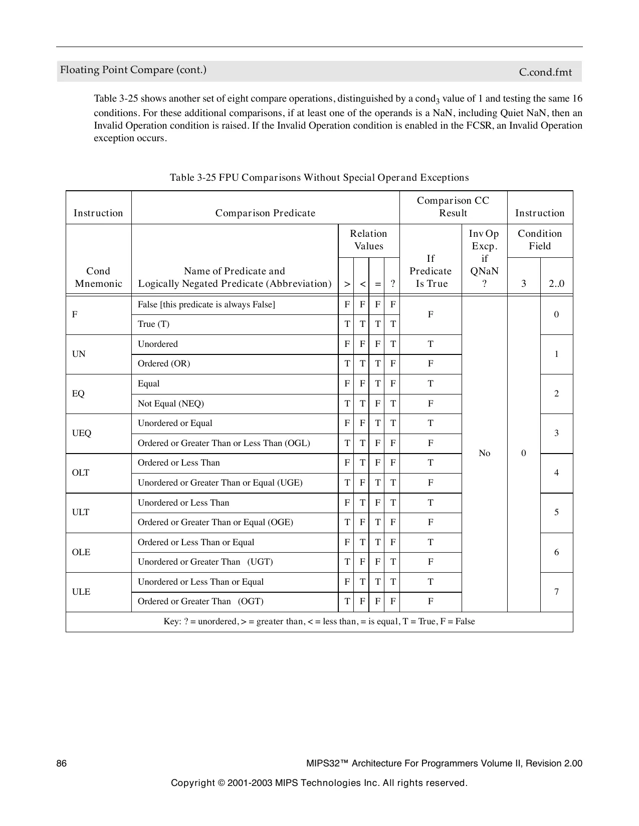
This page is a drawing, shown as the original scan.
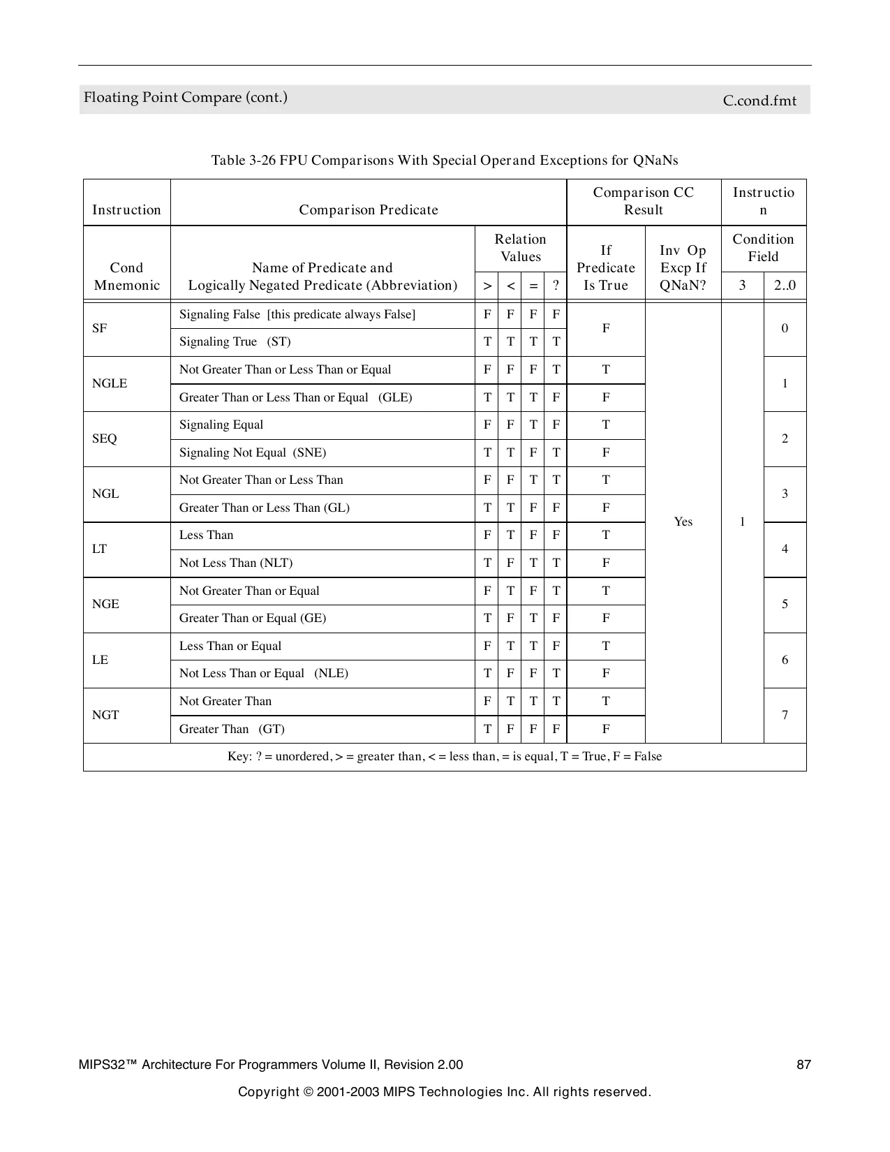
This page is a drawing, shown as the original scan.
Floating Point Compare (cont.) C.cond.fmt
Restrictions:
The fields fs and ft must specify FPRs valid for operands of type fmt; if they are not valid, the result is UNPREDICT- ABLE.
The operands must be values in format fmt; if they are not, the result is UNPREDICTABLE and the value of the operand FPRs becomes UNPREDICTABLE.
The result of C.cond.PS is UNPREDICTABLE if the processor is executing in 16 FP registers mode, or if the condition code number is odd.
Operation: if SNaN(ValueFPR(fs, fmt)) or SNaN(ValueFPR(ft, fmt)) or QNaN(ValueFPR(fs, fmt)) or QNaN(ValueFPR(ft, fmt)) then less ← false equal ← false unordered ← true if (SNaN(ValueFPR(fs,fmt)) or SNaN(ValueFPR(ft,fmt))) or (cond 3 and (QNaN(ValueFPR(fs,fmt)) or QNaN(ValueFPR(ft,fmt)))) then SignalException(InvalidOperation) endif else less ← ValueFPR(fs, fmt) < fmt ValueFPR(ft, fmt) equal ← ValueFPR(fs, fmt) = fmt ValueFPR(ft, fmt) unordered ← false endif condition ← (cond 2 and less) or (cond 1 and equal) or (cond 0 and unordered) SetFPConditionCode(cc, condition)
For c.cond.PS, the pseudo code above is repeated for both halves of the operand registers, treating each half as an independent single-precision values. Exceptions on the two halves are logically ORed and reported together. The results of the lower half comparison are written to condition code CC; the results of the upper half comparison are written to condition code CC+1.
Floating Point Compare (cont.) C.cond.fmt
Exceptions:
Coprocessor Unusable, Reserved Instruction
Floating Point Exceptions:
Unimplemented Operation, Invalid Operation
Programming Notes:
FP computational instructions, including compare, that receive an operand value of Signaling NaN raise the Invalid Operation condition. Comparisons that raise the Invalid Operation condition for Quiet NaNs in addition to SNaNs permit a simpler programming model if NaNs are errors. Using these compares, programs do not need explicit code to check for QNaNs causing the unordered relation. Instead, they take an exception and allow the exception handling system to deal with the error when it occurs. For example, consider a comparison in which we want to know if two numbers are equal, but for which unordered would be an error.
# comparisons using explicit tests for QNaN c.eq.d $f2,$f4# check for equal nop bc1t L2 # it is equal c.un.d $f2,$f4# it is not equal, # but might be unordered bc1t ERROR # unordered goes off to an error handler # not-equal-case code here
# equal-case code here L2: # -------------------------------------------------------------- # comparison using comparisons that signal QNaN c.seq.d $f2,$f4 # check for equal nop bc1t L2 # it is equal nop # it is not unordered here
# not-equal-case code here
# equal-case code here
CACHE
Perform Cache Operation CACHE
26 25 21 20 16 15
CACHE base op offset 101111
Format: CACHE op, offset(base) MIPS32
Purpose:
To perform the cache operation specified by op.
Description:
The 16-bit offset is sign-extended and added to the contents of the base register to form an effective address. The effective address is used in one of the following ways based on the operation to be performed and the type of cache as described in the following table.
Table 3-27 Usage of Effective Address
Operation Requires an Type of Cache
Address Virtual The effective address is used to address the cache. It is implementation dependent whether an address translation is performed on the effective address (with the possibility that a TLB Refill or TLB Invalid exception might occur)
Address Physical The effective address is translated by the MMU to a physical address. The physical address is then used to address the cache Usage of Effective Address
The effective address is translated by the MMU to a physical address. It is implementation dependent whether the effective address or the translated physical address is used to index the cache.
Assuming that the total cache size in bytes is CS, the associativity is A, and the number of bytes per tag is BPT, the following calculations give the fields of the address which specify the way and the index:
Index N/A OffsetBit ← Log2(BPT) IndexBit ← Log2(CS / A) WayBit ← IndexBit + Ceiling(Log2(A))
Way ← Addr WayBit-1..IndexBit Index ← Addr IndexBit-1..OffsetBit
For a direct-mapped cache, the Way calculation is ignored and the Index value fully specifies the cache tag. This is shown symbolically in the figure below.
Perform Cache Operation CACHE
Figure 3-2 Usage of Address Fields to Select Index and Way
WayBit OffsetBit IndexBit
Unused Way byte index Index
A TLB Refill and TLB Invalid (both with cause code equal TLBL) exception can occur on any operation. For index operations (where the address is used to index the cache but need not match the cache tag) software should use unmapped addresses to avoid TLB exceptions. This instruction never causes TLB Modified exceptions nor TLB Refill exceptions with a cause code of TLBS.
The effective address may be an arbitrarily-aligned by address. The CACHE instruction never causes an Address Error Exception due to an non-aligned address.
A Cache Error exception may occur as a byproduct of some operations performed by this instruction. For example, if a Writeback operation detects a cache or bus error during the processing of the operation, that error is reported via a Cache Error exception. Similarly, a Bus Error Exception may occur if a bus operation invoked by this instruction is terminated in an error. However, cache error exceptions should must be triggered by an Index Load Tag or Index Store tag operation, as these operations are used for initialization and diagnostic purposes.
An Address Error Exception (with cause code equal AdEL) may occur if the effective address references a portion of the kernel address space which would normally result in such an exception. It is implementation dependent whether such an exception does occur.
It is implementation dependent whether a data watch is triggered by a cache instruction whose address matches the Watch register address match conditions.
Bits [17:16] of the instruction specify the cache on which to perform the operation, as follows: Table 3-28 Encoding of Bits[17:16] of CACHE Instruction
Code Name Cache
2#00 I Primary Instruction
2#01 D Primary Data or Unified Primary
2#10 T Tertiary
2#11 S Secondary
Bits [20:18] of the instruction specify the operation to perform. To provide software with a consistent base of cache operations, certain encodings must be supported on all processors. The remaining encodings are recommended.
Perform Cache Operation CACHE
Table 3-29 Encoding of Bits [20:18] of the CACHE Instruction
Code Caches Name Effective Address Operand Type Operation Compliance
Set the state of the cache block at the specified index to invalid. I Index Invalidate Index
D Index Writeback Invalidate / Index Invalidate Index
2#000
S, T
2#001 All Index Writeback Invalidate / Index Invalidate
Index Load Tag This required encoding may be used by software to invalidate the entire instruction cache by stepping through all valid indices.
For a write-back cache: If the state of the cache block at the specified index is valid and dirty, write the block back to the memory address specified by the cache tag. After that operation is completed, set the state of the cache block to invalid. If the block is valid but not dirty, set the state of the block to invalid. Required
Required
For a write-through cache: Set the state of the cache block at the specified index to invalid. Index
Index This required encoding may be used by software to invalidate the entire data cache by stepping through all valid indices. Note that Index Store Tag should be used to initialize the cache at powerup.
Read the tag for the cache block at the specified index into the TagLo and TagHi Coprocessor 0 registers. If the DataLo and DataHi registers are implemented, also read the data corresponding to the byte index into the DataLo and DataHi registers. This operation must not cause a Cache Error Exception. Optional
Recommended The granularity and alignment of the data read into the DataLo and DataHi registers is implementation-dependent, but is typically the result of an aligned access to the cache, ignoring the appropriate low-order bits of the byte index.
Table 3-29 Encoding of Bits [20:18] of the CACHE Instruction
Code Caches Name Effective Address Operand Type Operation Compliance
Write the tag for the cache block at the specified index from the TagLo and TagHi Coprocessor 0 registers. This operation must not cause a Cache Error Exception.
2#010 All Index Store Tag Index
2#011 All Implementation Dependent Unspecified
I, D Hit Invalidate Address
2#100 This required encoding may be used by software to initialize the entire instruction or data caches by stepping through all valid indices. Doing so requires that the TagLo and TagHi registers associated with the cache be initialized first. Required
Available for implementation-dependent operation. Optional
If the cache block contains the specified address, set the state of the cache block to invalid. Required (Instruction Cache Encoding Only), Recommended otherwise This required encoding may be used by software to invalidate a range of addresses from the instruction cache by stepping through the address range by the line size of the cache. S, T Hit Invalidate Address Optional
Table 3-29 Encoding of Bits [20:18] of the CACHE Instruction
Code Caches Name Effective Address Operand Type
I Fill Address
D Hit Writeback Invalidate / Hit Invalidate Address Operation Compliance
Fill the cache from the specified address.
2#101 For a write-back cache: If the cache block contains the specified address and it is valid and dirty, write the contents back to memory. After that operation is completed, set the state of the cache block to invalid. If the block is valid but not dirty, set the state of the block to invalid. Required
For a write-through cache: If the cache block contains the specified address, set the state of the cache block to invalid. S, T Hit Writeback Invalidate / Hit Invalidate Address This required encoding may be used by software to invalidate a range of addresses from the data cache by stepping through the address range by the line size of the cache. Optional
D Hit Writeback Address Recommended
S, T Hit Writeback Address If the cache block contains the specified address and it is valid and dirty, write the contents back to memory. After the operation is completed, leave the state of the line valid, but clear the dirty state. For a write-through cache, this operation may be treated as a nop. 2#110 Recommended
Optional
Table 3-29 Encoding of Bits [20:18] of the CACHE Instruction
Code Caches Name Effective Address Operand Type Operation Compliance
If the cache does not contain the specified address, fill it from memory, performing a writeback if required, and set the state to valid and locked. If the cache already contains the specified address, set the state to locked. In set-associative or fully-associative caches, the way selected on a fill from memory is implementation dependent.
2#111 I, D Fetch and Lock Address The lock state may be cleared by executing an Index Invalidate, Index Writeback Invalidate, Hit Invalidate, or Hit Writeback Invalidate operation to the locked line, or via an Index Store Tag operation to the line that clears the lock bit. Note that clearing the lock state via Index Store Tag is dependent on the implementation-dependent cache tag and cache line organization, and that Index and Index Writeback Invalidate operations are dependent on cache line organization. Only Hit and Hit Writeback Invalidate operations are generally portable across implementations. Recommended
It is implementation dependent whether a locked line is displaced as the result of an external invalidate or intervention that hits on the locked line. Software must not depend on the locked line remaining in the cache if an external invalidate or intervention would invalidate the line if it were not locked.
It is implementation dependent whether a Fetch and Lock operation affects more than one line. For example, more than one line around the referenced address may be fetched and locked. It is recommended that only the single line containing the referenced address be affected.
Perform Cache Operation (cont.) CACHE
Restrictions:
The operation of this instruction is UNDEFINED for any operation/cache combination that is not implemented.
The operation of this instruction is UNDEFINED if the operaation requires an address, and that address is uncacheable.
The operation of the instruction is UNPREDICTABLE if the cache line that contains the CACHE instruction is the target of an invalidate or a writeback invalidate.
If access to Coprocessor 0 is not enabled, a Coprocessor Unusable Exception is signaled.
Operation: vAddr ← GPR[base] + sign_extend(offset) (pAddr, uncached) ← AddressTranslation(vAddr, DataReadReference) CacheOp(op, vAddr, pAddr)
Exceptions:
TLB Refill Exception.
TLB Invalid Exception
Coprocessor Unusable Exception
Address Error Exception
Cache Error Exception
Bus Error Exception
CEIL.L.fmt
Fixed Point Ceiling Convert to Long Fixed Point
26 25 21 20
COP1 CEIL.L.fmt
16 15
fmt 010001
CEIL.L.S fd, fs
CEIL.L.D fd, fs CEIL.L fs fd 00000
Format: 11 10
001010
MIPS64 MIPS32 Release 2 MIPS64 MIPS32 Release 2
Purpose:
To convert an FP value to 64-bit fixed point, rounding up
Description: fd ← convert_and_round(fs)
The value in FPR fs, in format fmt, is converted to a value in 64-bit long fixed point format and rounding toward +∞ (rounding mode 2). The result is placed in FPR fd.
When the source value is Infinity, NaN, or rounds to an integer outside the range -2 63 to 2 63 -1, the result cannot be represented correctly, an IEEE Invalid Operation condition exists, a d the Invalid Operation flag is set in the FCSR. If the Invalid Operation Enable bit is set in the FCSR, no result is written to fd and an Invalid Operation exception is taken immediately. Otherwise, the default result, 2 63 –1, is written to fd.
Restrictions:
The fields fs and fd must specify valid FPRs; fs for type fmt and fd for long fixed point; if they are not valid, the result is UNPREDICTABLE.
The operand must be a value in format fmt; if it is not, the result is UNPREDICTABLE and the value of the operand FPR becomes UNPREDICTABLE.
The result of this instruction is UNPREDICTABLE if the processor is executing in 16 FP registers mode.
Operation:
StoreFPR(fd, L, ConvertFmt(ValueFPR(fs, fmt), fmt, L))
Fixed Point Ceiling Convert to Long Fixed Point (cont.) CEIL.L.fmt
Exceptions:
Coprocessor Unusable, Reserved Instruction
Floating Point Exceptions:
Invalid Operation, Unimplemented Operation, Inexact, Overflow
CEIL.W.fmt
Floating Point Ceiling Convert to Word Fixed Point
26 25 21 20
COP1 CEIL.W.fmt
16 15
fmt 010001
CEIL.W.S CEIL.W.D CEIL.W fs fd 00000
Format: 11 10
001110
fd, fs fd, fs MIPS32 MIPS32
Purpose:
To convert an FP value to 32-bit fixed point, rounding up
Description: fd ← convert_and_round(fs)
The value in FPR fs, in format fmt, is converted to a value in 32-bit word fixed point format and rounding toward +∞ (rounding mode 2). The result is placed in FPR fd.
When the source value is Infinity, NaN, or rounds to an integer outside the range -2 31 to 2 31 -1, the result cannot be represented correctly, an IEEE Invalid Operation condition exists, and the Invalid Operation flag is set in the FCSR. If the Invalid Operation Enable bit is set in the FCSR, no result is written to fd and an Invalid Operation exception is taken immediately. Otherwise, the default result, 2 31 –1, is written to fd.
Restrictions:
The fields fs and fd must specify valid FPRs; fs for type fmt and fd for word fixed point; if they are not valid, the result is UNPREDICTABLE.
The operand must be a value in format fmt; if it is not, the result is UNPREDICTABLE and the value of the operand FPR becomes UNPREDICTABLE.
Operation:
StoreFPR(fd, W, ConvertFmt(ValueFPR(fs, fmt), fmt, W))
Exceptions:
Coprocessor Unusable, Reserved Instruction
Floating Point Exceptions:
Invalid Operation, Unimplemented Operation, Inexact, Overflow
CFC1
Move Control Word From Floating Point
26 25 CFC1
21 20
COP1 CF
010001 00010 16 15
rt
Format: 11 10
fs 000 0000 0000
MIPS32 CFC1 rt, fs
Purpose:
To copy a word from an FPU control register to a GPR
Description: rt ← FP_Control[fs]
Copy the 32-bit word from FP (coprocessor 1) control register fs into GPR rt.
Restrictions:
There are a few control registers defined for the floating point unit. The result is UNPREDICTABLE if fs specifies a register that does not exist.
Operation:
if fs = 0 then temp ← FIR elseif fs = 25 then temp ← 0 24 || FCSR 31..25 || FCSR 23 elseif fs = 26 then temp ← 0 14 || FCSR 17..12 || 0 5 || FCSR 6..2 || 0 2 elseif fs = 28 then temp ← 0 20 || FCSR 11.7 || 0 4 || FCSR 24 || FCSR 1..0 elseif fs = 31 then temp ← FCSR else temp ← UNPREDICTABLE endif GPR[rt] ← temp
Move Control Word From Floating Point (cont.) CFC1
Exceptions:
Coprocessor Unusable, Reserved Instruction
Historical Information:
For the MIPS I, II and III architectures, the contents of GPR rt are UNPREDICTABLE for the instruction immediately following CFC1.
MIPS V and MIPS32 introduced the three control registers that access portions of FCSR. These registers were not available in MIPS I, II, III, or IV.
CFC2
Move Control Word From Coprocessor 2
26 25 21 20 COP2 CF
010010 00010
Format: CFC2
16 15 11 10
rt Impl
MIPS32 CFC2 rt, rd
The syntax shown above is an example using CFC1 as a model. The specific syntax is implementation dependent.
Purpose:
To copy a word from a Coprocessor 2 control register to a GPR
Description: rt ← CP2CCR[Impl]
Copy the 32-bit word from the Coprocessor 2 control register denoted by the Impl field. The interpretation of the Impl field is left entirely to the Coprocessor 2 implementation and is not specified by the architecture.
Restrictions:
The result is UNPREDICTABLE if Impl specifies a register that does not exist.
Operation: temp ← CP2CCR[Impl] GPR[rt] ← temp
Exceptions:
Coprocessor Unusable, Reserved Instruction
CLO
Count Leading Ones in Word
26 25 CLO
21 20 16 15 11 10
SPECIAL2 rs rt CLO
00000 100001 rd 011100
Format: CLO rd, rs MIPS32
Purpose:
To Count the number of leading ones in a word
Description: rd ← count_leading_ones rs
Bits 31..0 of GPR rs are scanned from most significant to least significant bit. The number of leading ones is counted and the result is written to GPR rd. If all of bits 31..0 were set in GPR rs, the result written to GPR rd is 32.
Restrictions:
To be compliant with the MIPS32 and MIPS64 Architecture, software must place the same GPR number in both the rt and rd fields of the instruction. The operation of the instruction is UNPREDICTABLE if the rt and rd fields of the instruction contain different values.
Operation: temp ← 32 for i in 31 .. 0 if GPR[rs] i = 0 then temp ← 31 - i break endif endfor GPR[rd] ← temp
Exceptions:
None
CLZ
Count Leading Zeros in Word
26 25 CLZ
21 20 16 15 11 10
SPECIAL2 rs rt CLZ
00000 100000 rd 011100
Format: CLZ rd, rs MIPS32
Purpose
Count the number of leading zeros in a word
Description: rd ← count_leading_zeros rs
Bits 31..0 of GPR rs are scanned from most significant to least significant bit. The number of leading zeros is counted and the result is written to GPR rd. If no bits were set in GPR rs, the result written to GPR rt is 32.
Restrictions:
To be compliant with the MIPS32 and MIPS64 Architecture, software must place the same GPR number in both the rt and rd fields of the instruction. The operation of the instruction is UNPREDICTABLE if the rt and rd fields of the instruction contain different values.
Operation: temp ← 32 for i in 31 .. 0 if GPR[rs] i = 1 then temp ← 31 - i break endif endfor GPR[rd] ← temp
Exceptions:
None
COP2
Coprocessor Operation to Coprocessor 2 COP2
26 25 24 COP2 CO
010010 cofun
Format: COP2 func MIPS32
Purpose:
To performance an operation to Coprocessor 2
Description: CoprocessorOperation(2, cofun)
An implementation-dependent operation is performance to Coprocessor 2, with the cofun value passed as an argument. The operation may specify and reference internal coprocessor registers, and may change the state of the coprocessor conditions, but does not modify state within the processor. Details of coprocessor operation and internal state are described in the documentation for each Coprocessor 2 implementation.
Restrictions:
Operation:
CoprocessorOperation(2, cofun)
Exceptions:
Coprocessor Unusable Reserved Instruction
CTC1
Move Control Word to Floating Point
26 25
COP1 CTC1
21 20 16 15
CT rt 010001 00110
Format: 11 10
CTC1 fs 000 0000 0000
MIPS32 rt, fs
Purpose:
To copy a word from a GPR to an FPU control register
Description: FP_Control[fs] ← rt
Copy the low word from GPR rt into the FP (coprocessor 1) control register indicated by fs.
Writing to the floating point Control/Status register, the FCSR, causes the appropriate exception if any Cause bit and its corresponding Enable bit are both set. The register is written before the exception occurs. Writing to FEXR to set a cause bit whose enable bit is already set, or writing to FENR to set an enable bit whose cause bit is already set causes the appropriate exception. The register is written before the exception occurs.
Restrictions:
There are a few control registers defined for the floating point unit. The result is UNPREDICTABLE if fs specifies a register that does not exist.
Move Control Word to Floating Point (cont.) CTC1
Operation: temp ← GPR[rt] 31..0 if fs = 25 then if temp 31..8 ≠ 0 24 then UNPREDICTABLE else FCSR ← temp 7..1 || FCSR 24 || temp 0 || FCSR 22..0 endif elseif fs = 26 then if temp 22..18 ≠ 0 then UNPREDICTABLE else FCSR ← FCSR 31..18 || temp 17..12 || FCSR 11..7 || temp 6..2 || FCSR 1..0 endif elseif fs = 28 then if temp 22..18 ≠ 0 then UNPREDICTABLE else FCSR ← FCSR 31..25 || temp 2 || FCSR 23..12 || temp 11..7 || FCSR 6..2 || temp 1..0 endif elseif fs = 31 then if temp 22..18 ≠ 0 then UNPREDICTABLE else FCSR ← temp endif else UNPREDICTABLE endif
Exceptions:
Coprocessor Unusable, Reserved Instruction
Floating Point Exceptions:
Unimplemented Operation, Invalid Operation, Division-by-zero, Inexact, Overflow, Underflow
Historical Information:
For the MIPS I, II and III architectures, the contents of floating point control register fs are undefined for the instruction immediately following CTC1.
MIPS V and MIPS32 introduced the three control registers that access portions of FCSR. These registers were not available in MIPS I, II, III, or IV.
CTC2
Move Control Word to Coprocessor 2
26 25 21 20 COP2 CT
010010 00110
Format: CTC2
16 15 11 10
rt Impl
MIPS32 CTC2 rt, rd
The syntax shown above is an example using CTC1 as a model. The specific syntax is implementation dependent.
Purpose:
To copy a word from a GPR to a Coprocessor 2 control register
Description: CP2CCR[Impl] ← rt
Copy the low word from GPR rt into the Coprocessor 2 control register denoted by the Impl field. The interpretation of the Impl field is left entirely to the Coprocessor 2 implementation and is not specified by the architecture.
Restrictions:
The result is UNPREDICTABLE if rd specifies a register that does not exist.
Operation: temp ← GPR[rt] CP2CCR[Impl] ← temp
Exceptions:
Coprocessor Unusable, Reserved Instruction
CVT.D.fmt
Floating Point Convert to Double Floating Point
26 25 21 20 COP1 CVT.D.fmt
16 15
fmt 010001 CVT.D fs fd 00000
Format: 11 10
100001
CVT.D.S fd, fs CVT.D.W fd, fs CVT.D.L fd, fs MIPS32 MIPS32 MIPS64 MIPS32 Release 2
Purpose:
To convert an FP or fixed point value to double FP
Description: fd ← convert_and_round(fs)
The value in FPR fs, in format fmt, is converted to a value in double floating point format and rounded according to the current rounding mode in FCSR. The result is placed in FPR fd. If fmt is S or W, then the operation is always exact.
Restrictions:
The fields fs and fd must specify valid FPRs—fs for type fmt and fd for double floating point—if they are not valid, the result is UNPREDICTABLE.
The operand must be a value in format fmt; if it is not, the result is UNPREDICTABLE and the value of the operand FPR becomes UNPREDICTABLE.
For CVT.D.L, the result of this instruction is UNPREDICTABLE if the processor is executing in 16 FP registers mode.
Operation:
StoreFPR (fd, D, ConvertFmt(ValueFPR(fs, fmt), fmt, D))
Exceptions:
Coprocessor Unusable, Reserved Instruction
Floating Point Exceptions:
Invalid Operation, Unimplemented Operation, Inexact
CVT.L.fmt
Floating Point Convert to Long Fixed Point
26 25 CVT.L.fmt
21 20
COP1 16 15
fmt 010001 CVT.L fs fd 00000
Format: 11 10
100101
MIPS64 MIPS32 Release 2 MIPS64 MIPS32 Release 2 CVT.L.S fd, fs
CVT.L.D fd, fs
Purpose:
To convert an FP value to a 64-bit fixed point
Description: fd ← convert_and_round(fs)
Convert the value in format fmt in FPR fs to long fixed point format and round according to the current rounding mode in FCSR. The result is placed in FPR fd.
When the source value is Infinity, NaN, or rounds to an integer outside the range -2 63 to 2 63 -1, the result cannot be represented correctly, an IEEE Invalid Operation condition exists, and the Invalid Operation flag is set in the FCSR. If the Invalid Operation Enable bit is set in the FCSR, no result is written to fd and an Invalid Operation exception is taken immediately. Otherwise, the default result, 2 63 –1, is written to fd.
Restrictions:
The fields fs and fd must specify valid FPRs—fs for type fmt and fd for long fixed point—if they are not valid, the result is UNPREDICTABLE.
The operand must be a value in format fmt; if it is not, the result is UNPREDICTABLE and the value of the operand FPR becomes UNPREDICTABLE.
The result of this instruction is UNPREDICTABLE if the processor is executing in 16 FP registers mode.
Operation:
StoreFPR (fd, L, ConvertFmt(ValueFPR(fs, fmt), fmt, L))
Floating Point Convert to Long Fixed Point, cont. CVT.L.fmt
Exceptions:
Coprocessor Unusable, Reserved Instruction
Floating Point Exceptions:
Invalid Operation, Unimplemented Operation, Inexact, Overflow
CVT.PS.S
Floating Point Convert Pair to Paired Single
26 25 CVT.PS.S
21 20 16 15 11 10 COP1 010001 fmt 10000 ft fs fd CVT.PS 100110
Format: MIPS64 MIPS32 Release 2 CVT.PS.S fd, fs, ft
Purpose:
To convert two FP values to a paired single value
Description: fd ← fs 31..0 || ft 31..0
The single-precision values in FPR fs and ft are written into FPR fd as a paired-single value. The value in FPR fs is written into the upper half, and the value in FPR ft is written into the lower half.
ft fs
fd
32 31
CVT.PS.S is similar to PLL.PS, except that it expects operands of format S instead of PS.
The move is non-arithmetic; it causes no IEEE 754 exceptions.
Restrictions:
The fields fs and ft must specify FPRs valid for operands of type S; if they are not valid, the result is UNPREDICT- ABLE.
The operand must be a value in format S; if it is not, the result is UNPREDICTABLE and the value of the operand FPR becomes UNPREDICTABLE.
The result of this instruction is UNPREDICTABLE if the processor is executing in 16 FP registers mode.
Floating Point Convert Pair to Paired Single (cont.) CVT.PS.S
Operation:
StoreFPR(fd, S, ValueFPR(fs,S) || ValueFPR(ft,S))
Exceptions:
Coprocessor Unusable, Reserved Instruction
Floating Point Exceptions:
Invalid Operation, Unimplemented Operation
CVT.S.fmt
Floating Point Convert to Single Floating Point
26 25 21 20
COP1 16 15 11 10
fmt 010001 CVT.S fs fd 00000
Format: CVT.S.fmt
100000
MIPS32 MIPS32 MIPS64 MIPS32 Release 2 CVT.S.D fd, fs CVT.S.W fd, fs CVT.S.L fd, fs
Purpose:
To convert an FP or fixed point value to single FP
Description: fd ← convert_and_round(fs)
The value in FPR fs, in format fmt, is converted to a value in single floating point format and rounded according to the current rounding mode in FCSR. The result is placed in FPR fd.
Restrictions:
The fields fs and fd must specify valid FPRs—fs for type fmt and fd for single floating point. If they are not valid, the result is UNPREDICTABLE.
The operand must be a value in format fmt; if it is not, the result is UNPREDICTABLE and the value of the operand FPR becomes UNPREDICTABLE.
For CVT.S.L, the result of this instruction is UNPREDICTABLE if the processor is executing in 16 FP registers mode.
Operation:
StoreFPR(fd, S, ConvertFmt(ValueFPR(fs, fmt), fmt, S))
Exceptions:
Coprocessor Unusable, Reserved Instruction
Floating Point Exceptions:
Invalid Operation, Unimplemented Operation, Inexact, Overflow, Underflow
CVT.S.PL
Floating Point Convert Pair Lower to Single Floating Point
26 25
COP1 21 20
fmt CVT.S.PL
16 15 11 10
010001 10110 00000 CVT.S.PL fs
Format: fd 101000
CVT.S.PL fd, fs MIPS64 MIPS32 Release 2
Purpose:
To convert one half of a paired single FP value to single FP
Description: fd ← convert_and_round(fs)
The lower paired single value in FPR fs, in format PS, is converted to a value in single floating point format and rounded according to the current rounding mode in FCSR. The result is placed in FPR fd. This instruction can be used to isolate the lower half of a paired single value.
Restrictions:
The fields fs and fd must specify valid FPRs—fs for type PS and fd for single floating point. If they are not valid, the result is UNPREDICTABLE.
The operand must be a value in format PS; if it is not, the result is UNPREDICTABLE and the value of the operand FPR becomes UNPREDICTABLE.
The result of CVT.S.PL is UNPREDICTABLE if the processor is executing in 16 FP registers mode.
Operation:
StoreFPR (fd, S, ConvertFmt(ValueFPR(fs, PS), PL, S))
Exceptions:
Coprocessor Unusable, Reserved Instruction
Floating Point Exceptions:
Invalid Operation, Unimplemented Operation, Inexact, Overflow, Underflow
CVT.S.PU
Floating Point Convert Pair Upper to Single Floating Point
26 25
COP1 21 20
fmt CVT.S.PU
16 15 11 10
010001 10110 00000 CVT.S.PU fs
Format: fd 100000
MIPS64 MIPS32 Release 2 CVT.S.PU fd, fs
Purpose:
To convert one half of a paired single FP value to single FP
Description: fd ← convert_and_round(fs)
The upper paired single value in FPR fs, in format PS, is converted to a value in single floating point format and rounded according to the current rounding mode in FCSR. The result is placed in FPR fd. This instruction can be used to isolate the upper half of a paired single value.
Restrictions:
The fields fs and fd must specify valid FPRs—fs for type PS and fd for single floating point. If they are not valid, the result is UNPREDICTABLE.
The operand must be a value in format PS; if it is not, the result is UNPREDICTABLE and the value of the operand FPR becomes UNPREDICTABLE.
The result of CVT.S.PU is UNPREDICTABLE if the processor is executing in 16 FP registers mode.
Operation:
StoreFPR (fd, S, ConvertFmt(ValueFPR(fs, PS), PU, S))
Exceptions:
Coprocessor Unusable, Reserved Instruction
Floating Point Exceptions:
Invalid Operation, Unimplemented Operation, Inexact, Overflow, Underflow
CVT.W.fmt
Floating Point Convert to Word Fixed Point
26 25 CVT.W.fmt
21 20 16 15 COP1 fmt 010001 CVT.W fs fd 00000
Format: 11 10
100100
CVT.W.S fd, fs CVT.W.D fd, fs MIPS32 MIPS32
Purpose:
To convert an FP value to 32-bit fixed point
Description: fd ← convert_and_round(fs)
The value in FPR fs, in format fmt, is converted to a value in 32-bit word fixed point format and rounded according to the current rounding mode in FCSR. The result is placed in FPR fd.
When the source value is Infinity, NaN, or rounds to an integer outside the range -2 31 to 2 31 -1, the result cannot be represented correctly, an IEEE Invalid Operation condition exists, and the Invalid Operation flag is set in the FCSR. If the Invalid Operation Enable bit is set in the FCSR, no result is written to fd and an Invalid Operation exception is taken immediately. Otherwise, the default result, 2 31 –1, is written to fd.
Restrictions:
The fields fs and fd must specify valid FPRs—fs for type fmt and fd for word fixed point—if they are not valid, the result is UNPREDICTABLE.
The operand must be a value in format fmt; if it is not, the result is UNPREDICTABLE and the value of the operand FPR becomes UNPREDICTABLE.
Operation:
StoreFPR(fd, W, ConvertFmt(ValueFPR(fs, fmt), fmt, W))
Exceptions:
Coprocessor Unusable, Reserved Instruction
Floating Point Exceptions:
Invalid Operation, Unimplemented Operation, Inexact, Overflow
DERET
Debug Exception Return DERET
26 25 24 COP0 CO DERET
010000 000 0000 0000 0000 0000 011111
Format: DERET EJTAG
Purpose:
To Return from a debug exception.
Description:
DERET clears execution and instruction hazards, returns from Debug Mode and resumes non-debug execution at the instruction whose address is contained in the DEPC register. DERET does not execute the next instruction (i.e. it has no delay slot).
Restrictions:
A DERET placed between an LL and SC instruction does not cause the SC to fail.
If the DEPC register with the return address for the DERET was modified by an MTC0 or a DMTC0 instruction, a CP0 hazard exists that must be removed via software insertion of the appropriate number of SSNOP instructions (for implementations of Release 1 of the Architecture) or by an EHB, or other execution hazard clearing instruction (for implementations of Release 2 of the Architecture).
DERET implements a software barrier that resolves all execution and instruction hazards created by Coprocessor 0 state changes (for Release 2 implementations, refer to the SYNCI instruction for additional information on resolving instruction hazards created by writing the instruction stream). The effects of this barrier are seen starting with the instruction fetch and decode of the instruction at the PC to which the DERET returns.
This instruction is legal only if the processor is executing in Debug Mode.The operation of the processor is UNDE- FINED if a DERET is executed in the delay slot of a branch or jump instruction.
Debug Exception Return (cont.) DERET
Operation: Debug DM ← 0 Debug IEXI ← 0 if IsMIPS16Implemented() then PC ← DEPC 31..1 || 0 ISAMode ← DEPC 0 else
PC ← DEPC
endif ClearHazards()
Exceptions:
Coprocessor Unusable Exception Reserved Instruction Exception
DI
Disable Interrupts DI
26 25 21 20 16 15 11 10
COP0 0100 00 MFMC0 01 011 rt 0110 0 000 00 sc 0 0
Format: MIPS32 Release 2 MIPS32 Release 2 DI DI rt
Purpose:
To return the previous value of the Status register and disable interrupts. If DI is specified without an argument, GPR r0 is implied, which discards the previous value of the Status register.
Description: rt ← Status; Status IE ← 0
The current value of the Status register is loaded into general register rt. The Interrupt Enable (IE) bit in the Status register is then cleared.
Restrictions:
If access to Coprocessor 0 is not enabled, a Coprocessor Unusable Exception is signaled.
In implementations prior to Release 2 of the architecture, this instruction resulted in a Reserved Instruction Exception.
Operation:
This operation specification is for the general interrupt enable/disable operation, with the sc field as a variable. The individual instructions DI and EI have a specific value for the sc field.
data ← Status GPR[rt] ← data Status IE ← 0
Disable Interrupts, cont. DI
Exceptions:
Coprocessor Unusable Reserved Instruction (Release 1 implementations)
Programming Notes:
The effects of this instruction are identical to those accomplished by the sequence of reading Status into a GPR, clearing the IE bit, and writing the result back to Status. Unlike the multiple instruction sequence, however, the DI instruction can not be aborted in the middle by an interrupt or exception.
This instruction creates an execution hazard between the change to the Status register and the point where the change to the interrupt enable takes effect. This hazard is cleared by the EHB, JALR.HB, JR.HB, or ERET instructions. Software must not assume that a fixed latency will clear the execution hazard.
DIV
Divide Word DIV
26 25 21 20 16 15
SPECIAL rs
Format: DIV
00 0000 0000 011010 rt 000000
MIPS32 DIV rs, rt
Purpose:
To divide a 32-bit signed integers
Description: (HI, LO) ← rs / rt
The 32-bit word value in GPR rs is divided by the 32-bit value in GPR rt, treating both operands as signed values. The 32-bit quotient is placed into special register LO and the 32-bit remainder isplaced into special register HI.
No arithmetic exception occurs under any circumstances.
Restrictions:
If the divisor in GPR rt is zero, the arithmetic result value is UNPREDICTABLE.
Operation: q LO r HI ← GPR[rs] 31..0 div GPR[rt] 31..0 ← q ← GPR[rs] 31..0 mod GPR[rt] 31..0 ← r
Exceptions:
None
Divide Word (cont.) DIV
Programming Notes:
No arithmetic exception occurs under any circumstances. If divide-by-zero or overflow conditions are detected and some action taken, then the divide instruction is typically followed by additional instructions to check for a zero divisor and/or for overflow. If the divide is asynchronous then the zero-divisor check can execute in parallel with the divide. The action taken on either divide-by-zero or overflow is either a convention within the program itself, or more typically within the system software; one possibility is to take a BREAK exception with a code field value to signal the problem to the system software.
As an example, the C programming language in a UNIX ® environment expects division by zero to either terminate the program or execute a program-specified signal handler. C does not expect overflow to cause any exceptional condition. If the C compiler uses a divide instruction, it also emits code to test for a zero divisor and execute a BREAK instruction to inform the operating system if a zero is detected.
In some processors the integer divide operation may proceed asynchronously and allow other CPU instructions to execute before it is complete. An attempt to read LO or HI before the results are written interlocks until the results are ready. Asynchronous execution does not affect the program result, but offers an opportunity for performance improvement by scheduling the divide so that other instructions can execute in parallel.
Historical Perspective:
In MIPS 1 through MIPS III, if either of the two instructions preceding the divide is an MFHI or MFLO, the result of the MFHI or MFLO is UNPREDICTABLE. Reads of the HI or LO special register must be separated from subsequent instructions that write to them by two or more instructions. This restriction was removed in MIPS IV and MIPS32 and all subsequent levels of the architecture.
DIV.fmt
Floating Point Divide DIV.fmt
26 25 21 20 16 15 11 10
COP1 DIV fmt ft fs fd 010001 000011
Format: MIPS32 MIPS32 DIV.S fd, fs, ft DIV.D fd, fs, ft
Purpose:
To divide FP values
Description: fd ← fs / ft
The value in FPR fs is divided by the value in FPR ft. The result is calculated to infinite precision, rounded according to the current rounding mode in FCSR, and placed into FPR fd. The operands and result are values in format fmt.
Restrictions:
The fields fs, ft, and fd must specify FPRs valid for operands of type fmt; if they are not valid, the result is UNPRED- ICABLE.
The operands must be values in format fmt; if they are not, the result is UNPREDICTABLE and the value of the operand FPRs becomes UNPREDICTABLE.
Operation:
StoreFPR (fd, fmt, ValueFPR(fs, fmt) / ValueFPR(ft, fmt))
Exceptions:
Coprocessor Unusable, Reserved Instruction
Floating Point Exceptions:
Inexact, Invalid Operation, Unimplemented Operation, Division-by-zero, Overflow, Underflow
DIVU
Divide Unsigned Word DIVU
26 25 21 20 16 15 SPECIAL rs
Format: DIVU
00 0000 0000 011011 rt 000000
DIVU rs, rt MIPS32
Purpose:
To divide a 32-bit unsigned integers
Description: (HI, LO) ← rs / rt
The 32-bit word value in GPR rs is divided by the 32-bit value in GPR rt, treating both operands as unsigned values. The 32-bit quotient is placed into special register LO and the 32-bit remainder is placed into special register HI.
No arithmetic exception occurs under any circumstances.
Restrictions:
If the divisor in GPR rt is zero, the arithmetic result value is UNPREDICTABLE.
Operation:
q r LO HI ← (0 || GPR[rs] 31..0 ) div (0 || GPR[rt] 31..0 ) ← (0 || GPR[rs] 31..0 ) mod (0 || GPR[rt] 31..0 ) ← sign_extend(q 31..0 ) ← sign_extend(r 31..0 )
Exceptions:
None
Programming Notes:
See “Programming Notes” for the DIV instruction.
Historical Perspective:
In MIPS 1 through MIPS III, if either of the two instructions preceding the divide is an MFHI or MFLO, the result of the MFHI or MFLO is UNPREDICTABLE. Reads of the HI or LO special register must be separated from subsequent instructions that write to them by two or more instructions. This restriction was removed in MIPS IV and MIPS32 and all subsequent levels of the architecture.
EHB
EHB Execution Hazard Barrier
26 25 21 20 16 15 11 10 SPECIAL SLL
000000 00000 00000 00000 00011 000000
Format: MIPS32 Release 2 EHB
Purpose:
To stop instruction execution until all execution hazards have been cleared.
Description:
EHB is the assembly idiom used to denote execution hazard barrier. The actual instruction is interpreted by the hardware as SLL r0, r0, 3.
This instruction alters the instruction issue behavior on a pipelined processor by stopping execution until all execution hazards have been cleared. Other than those that might be created as a consequence of setting Status CU0 , there are no execution hazards visible to an unprivileged program running in User Mode. All execution hazards created by previous instructions are cleared for instructions executed immediately following the EHB, even if the EHB is executed in the delay slot of a branch or jump. The EHB instruction does not clear instruction hazards - such hazards are cleared by the JALR.HB, JR.HB, and ERET instructions.
Restrictions:
None
Operation:
ClearExecutionHazards()
Exceptions:
None
Programming Notes:
In MIPS32 Release 2 implementations, this instruction resolves all execution hazards. On a superscalar processor, EHB has alters the instruction issue behavior in a manner identical to SSNOP. For backward compatibility with Release 1 implementations, the last of a sequence of SSNOPs can be replaced by an EHB. In Release 1 implementations, the EHB will be treated as an SSNOP, thereby preserving the semantics of the sequence. In Release 2 implementations, replacing the final SSNOP with an EHB should have no performance effect because a properly sized sequence of SSNOPs will have already cleared the hazard. As EHB becomes the standard in MIPS implementations, the previous SSNOPs can be removed, leaving only the EHB.
EI
Enable Interrupts EI
26 25 21 20 16 15 11 10
COP0 0100 00 MFMC0 01 011 rt 0110 0 000 00 sc 0 0
Format: MIPS32 Release 2 MIPS32 Release 2 EI EI rt
Purpose:
To return the previous value of the Status register and enable interrupts. If EI is specified without an argument, GPR r0 is implied, which discards the previous value of the Status register.
Description: rt ← Status; Status IE ← 1
The current value of the Status register is loaded into general register rt. The Interrupt Enable (IE) bit in the Status register is then set.
Restrictions:
If access to Coprocessor 0 is not enabled, a Coprocessor Unusable Exception is signaled.
In implementations prior to Release 2 of the architecture, this instruction resulted in a Reserved Instruction Exception.
Operation:
This operation specification is for the general interrupt enable/disable operation, with the sc field as a variable. The individual instructions DI and EI have a specific value for the sc field.
data ← Status GPR[rt] ← data Status IE ← 1
Enable Interrupts, cont. EI
Exceptions:
Coprocessor Unusable Reserved Instruction (Release 1 implementations)
Programming Notes:
The effects of this instruction are identical to those accomplished by the sequence of reading Status into a GPR, setting the IE bit, and writing the result back to Status. Unlike the multiple instruction sequence, however, the EI instruction can not be aborted in the middle by an interrupt or exception.
This instruction creates an execution hazard between the change to the Status register and the point where the change to the interrupt enable takes effect. This hazard is cleared by the EHB, JALR.HB, JR.HB, or ERET instructions. Software must not assume that a fixed latency will clear the execution hazard.
ERET
ERET Exception Return
26 25 24 COP0 CO ERET
010000 000 0000 0000 0000 0000 011000
Format: ERET MIPS32
Purpose:
To return from interrupt, exception, or error trap.
Description:
ERET clears execution and instruction hazards, conditionally restores SRSCtl CSS from SRSCtl PSS in a Release 2 implementation, and returns to the interrupted instruction at the completion of interrupt, exception, or error processing. ERET does not execute the next instruction (i.e., it has no delay slot).
Restrictions:
The operation of the processor is UNDEFINED if an ERET is executed in the delay slot of a branch or jump instruction.
An ERET placed between an LL and SC instruction will always cause the SC to fail.
ERET implements a software barrier that resolves all execution and instruction hazards created by Coprocessor 0 state changes (for Release 2 implementations, refer to the SYNCI instruction for additional information on resolving instruction hazards created by writing the instruction stream). The effects of this barrier are seen starting with the instruction fetch and decode of the instruction at the PC to which the ERET returns.
In a Release 2 implementation, ERET does not restore SRSCtl CSS from SRSCtl PSS if Status BEV = 1, or if Status ERL = 1 because any exception that sets Status ERL to 1 (Reset, Soft Reset, NMI, or cache error) does not save SRSCtl CSS in SRSCtl PSS . If software sets Status ERL to 1, it must be aware of the operation of an ERET that may be subsequently executed.
ERET Exception Return
Operation:
if Status ERL = 1 then temp ← ErrorEPC Status ERL ← 0 else temp ← EPC Status EXL ← 0 if (ArchitectureRevision ≥ 2) and (SRSCtl HSS > 0) and (Status BEV = 0)then
SRSCtl CSS ← SRSCtl PSS
endif endif if IsMIPS16Implemented() then PC ← temp 31..1 || 0 ISAMode ← temp 0 else PC ← temp endif LLbit ← 0 ClearHazards()
Exceptions: Coprocessor Unusable Exception
EXT
Extract Bit Field EXT
26 25 21 20 16 15 11 10
SPECIAL3 rs rt 011111
Format: EXT msbd (size-1) lsb (pos) 000000
MIPS32 Release 2 ext rt, rs, pos, size
Purpose:
To extract a bit field from GPR rs and store it right-justified into GPR rt.
Description: rt ← ExtractField(rs, msbd, lsb)
The bit field starting at bit pos and extending for size bits is extracted from GPR rs and stored zero-extended and right-justified in GPR rt. The assembly language arguments pos and size are converted by the assembler to the instruction fields msbd (the most significant bit of the destination field in GPR rt), in instruction bits 15..11, and lsb (least significant bit of the source field in GPR rs), in instruction bits 10..6, as follows: msbd ← size-1 lsb ← pos
The values of pos and size must satisfy all of the following relations: 0 ≤ pos < 32 0 < size ≤ 32 0 < pos+size ≤ 32
Figure 3-3 shows the symbolic operation of the instruction.
GPR rs Initial Value pos+size pos+size-1 lsb+msbd+1 lsb+msbd
IJKL MNOP QRST
32-(pos+size) 32-(lsb+msbd+1) size msbd+1 pos lsb
size size-1 msbd+1 msbd
GPR rt Final Value pos pos-1 lsb lsb-1
MNOP
32-size 32-(msbd+1) size msbd+1
Figure 3-3 Operation of the EXT Instruction
Restrictions:
In implementations prior to Release of the architecture, this instruction resulted in a Reserved Instruction Exception.
The operation is UNPREDICTABLE if lsb+msbd > 31.
Extract Bit Field, cont. EXT
Operation:
if (lsb + msbd) > 31) then UNPREDICTABLE endif temp ← 0 32-(msbd+1) || GPR[rs] msbd+lsb..lsb GPR[rt] ← temp
Exceptions:
Reserved Instruction
FLOOR.L.fmt
Floating Point Floor Convert to Long Fixed Point
26 25 21 20
COP1 FLOOR.L.fmt
16 15
fmt 010001 FLOOR.L fs fd 00000
Format: 11 10
001011
FLOOR.L.S fd, fs
FLOOR.L.D fd, fs MIPS64 MIPS32 Release 2 MIPS64 MIPS32 Release 2
Purpose:
To convert an FP value to 64-bit fixed point, rounding down
Description: fd ← convert_and_round(fs)
The value in FPR fs, in format fmt, is converted to a value in 64-bit long fixed point format and rounded toward -∞ (rounding mode 3). The result is placed in FPR fd.
When the source value is Infinity, NaN, or rounds to an integer outside the range -2 63 to 2 63 -1, the result cannot be represented correctly, an IEEE Invalid Operation condition exists, and the Invalid Operation flag is set in the FCSR. If the Invalid Operation Enable bit is set in the FCSR, no result is written to fd and an Invalid Operation exception is taken immediately. Otherwise, the default result, 2 63 –1, is written to fd.
Restrictions:
The fields fs and fd must specify valid FPRs—fs for type fmt and fd for long fixed point—if they are not valid, the result is UNPREDICTABLE.
The operand must be a value in format fmt; if it is not, the result is UNPREDICTABLE and the value of the operand FPR becomes UNPREDICTABLE.
The result of this instruction is UNPREDICTABLE if the processor is executing in 16 FP registers mode.
Operation:
StoreFPR(fd, L, ConvertFmt(ValueFPR(fs, fmt), fmt, L))
Floating Point Floor Convert to Long Fixed Point (cont.) FLOOR.L.fmt
Exceptions:
Coprocessor Unusable, Reserved Instruction
Floating Point Exceptions:
Invalid Operation, Unimplemented Operation, Inexact, Overflow
FLOOR.W.fmt
Floating Point Floor Convert to Word Fixed Point
26 25 21 20
COP1 FLOOR.W.fmt
16 15
fmt 010001
FLOOR.W.S FLOOR.W.D FLOOR.W fs fd 00000
Format: 11 10
001111
fd, fs fd, fs MIPS32 MIPS32
Purpose:
To convert an FP value to 32-bit fixed point, rounding down
Description: fd ← convert_and_round(fs)
The value in FPR fs, in format fmt, is converted to a value in 32-bit word fixed point format and rounded toward –∞ (rounding mode 3). The result is placed in FPR fd.
When the source value is Infinity, NaN, or rounds to an integer outside the range -2 31 to 2 31 -1, the result cannot be represented correctly, an IEEE Invalid Operation condition exists, and the Invalid Operation flag is set in the FCSR. If the Invalid Operation Enable bit is set in the FCSR, no result is written to fd and an Invalid Operation exception is taken immediately. Otherwise, the default result, 2 31 –1, is written to fd.
Restrictions:
The fields fs and fd must specify valid FPRs—fs for type fmt and fd for word fixed point—if they are not valid, the result is UNPREDICTABLE.
The operand must be a value in format fmt; if it is not, the result is UNPREDICTABLE and the value of the operand FPR becomes UNPREDICTABLE.
Operation:
StoreFPR(fd, W, ConvertFmt(ValueFPR(fs, fmt), fmt, W))
Exceptions:
Coprocessor Unusable, Reserved Instruction
Floating Point Exceptions:
Invalid Operation, Unimplemented Operation, Inexact, Overflow
INS
Insert Bit Field INS
26 25 21 20 16 15
SPECIAL3
Format: rs rt msb (pos+size-1) lsb (pos) INS 000100 011111 11 10
MIPS32 Release 2 ins rt, rs, pos, size
Purpose:
To merge a right-justified bit field from GPR rs into a specified field in GPR rt.
Description: rt ← InsertField(rt, rs, msb, lsb)
The right-most size bits from GPR rs are merged into the value from GPR rt starting at bit position pos. The result isplaced back in GPR rt. The assembly language arguments pos and size are converted by the assembler to the instruction fields msb (the most significant bit of the field), in instruction bits 15..11, and lsb (least significant bit of the field), in instruction bits 10..6, as follows: msb ← pos+size-1 lsb ← pos
The values of pos and size must satisfy all of the following relations: 0 ≤ pos < 32 0 < size ≤ 32 0 < pos+size ≤ 32
Figure 3-4 shows the symbolic operation of the instruction.
size size-1 msb-lsb+1 msb-lsb
GPR rs
32-size 32-(msb-lsb+1) size msb-lsb+1
pos pos-1 lsb lsb-1
IJKL MNOP QRST
32-(pos+size) 32-(msb+1) size msb-lsb+1 pos lsb
pos+size pos+size-1 msb+1 msb
GPR rt Final Value EFGH
pos+size pos+size-1 msb+1 msb
GPR rt Initial Value ABCD
pos lsb pos-1 lsb-1
IJKL EFGH QRST
32-(pos+size) 32-(msb+1) size msb-lsb+1 pos lsb
Figure 3-4 Operation of the INS Instruction
Insert Bit Field, cont. INS
Restrictions:
In implementations prior to Release 2 of the architecture, this instruction resulted in a Reserved Instruction Exception.
The operation is UNPREDICTABLE if lsb > msb.
Operation:
if lsb > msb) then UNPREDICTABLE endif GPR[rt] ← GPR[rt] 31..msb+1 || GPR[rs] msb-lsb..0 || GPR[rt] lsb-1..0
Exceptions:
Reserved Instruction
J Jump J
26 25 J instr_index 000010
Format: MIPS32 J target
Purpose:
To branch within the current 256 MB-aligned region
Description:
This is a PC-region branch (not PC-relative); the effective target address is in the “current” 256 MB-aligned region. The low 28 bits of the target address is the instr_index field shifted left 2 bits. The remaining upper bits are the corresponding bits of the address of the instruction in the delay slot (not the branch itself).
Jump to the effective target address. Execute the instruction that follows the jump, in the branch delay slot, before executing the jump itself.
Restrictions:
Processor operation is UNPREDICTABLE if a branch, jump, ERET, DERET, or WAIT instruction is placed in the delay slot of a branch or jump.
Operation:
I: I+1:PC ← PC GPRLEN-1..28 || instr_index || 0 2
Exceptions:
None
Programming Notes:
Forming the branch target address by catenating PC and index bits rather than adding a signed offset to the PC is an advantage if all program code addresses fit into a 256 MB region aligned on a 256 MB boundary. It allows a branch from anywhere in the region to anywhere in the region, an action not allowed by a signed relative offset.
This definition creates the following boundary case: When the jump instruction is in the last word of a 256 MB region, it can branch only to the following 256 MB region containing the branch delay slot.
JAL Jump and Link JAL
26 25 JAL instr_index 000011
Format: JAL target MIPS32
Purpose:
To execute a procedure call within the current 256 MB-aligned region
Description:
Place the return address link in GPR 31. The return link is the address of the second instruction following the branch, at which location execution continues after a procedure call.
This is a PC-region branch (not PC-relative); the effective target address is in the “current” 256 MB-aligned region. The low 28 bits of the target address is the instr_index field shifted left 2 bits. The remaining upper bits are the corresponding bits of the address of the instruction in the delay slot (not the branch itself).
Jump to the effective target address. Execute the instruction that follows the jump, in the branch delay slot, before executing the jump itself.
Restrictions:
Processor operation is UNPREDICTABLE if a branch, jump, ERET, DERET, or WAIT instruction is placed in the delay slot of a branch or jump.
Operation:
I: GPR[31]← PC + 8 I+1:PC ← PC GPRLEN-1..28 || instr_index || 0 2
Exceptions:
None
Programming Notes:
Forming the branch target address by catenating PC and index bits rather than adding a signed offset to the PC is an advantage if all program code addresses fit into a 256 MB region aligned on a 256 MB boundary. It allows a branch from anywhere in the region to anywhere in the region, an action not allowed by a signed relative offset.
This definition creates the following boundary case: When the branch instruction is in the last word of a 256 MB region, it can branch only to the following 256 MB region containing the branch delay slot.
JALR Jump and Link Register JALR
26 25 21 20 SPECIAL 16 15
000000 rd hint 00000 JALR rs
Format: 11 10
001001
MIPS32 MIPS32 JALR rs (rd = 31 implied) JALR rd, rs
Purpose:
To execute a procedure call to an instruction address in a register
Description: rd ← return_addr, PC ← rs Place the return address link in GPR rd. The return link is the address of the second instruction following the branch, where execution continues after a procedure call.
For processors that do not implement the MIPS16e ASE:
- Jump to the effective target address in GPR rs. Execute the instruction that follows the jump, in the branch delay slot, before executing the jump itself.
For processors that do implement the MIPS16e ASE:
- Jump to the effective target address in GPR rs. Execute the instruction that follows the jump, in the branch delay slot, before executing the jump itself. Set the ISA Mode bit to the value in GPR rs bit 0. Bit 0 of the target address is always zero so that no Address Exceptions occur when bit 0 of the source register is one
In release 1 of the architecture, the only defined hint field value is 0, which sets default handling of JALR. In Release 2 of the architecture, bit 10 of the hint field is used to encode a hazard barrier. See the JALR.HB instruction description for additional information.
Restrictions:
Register specifiers rs and rd must not be equal, because such an instruction does not have the same effect when reexecuted. The result of executing such an instruction is UNPREDICTABLE. This restriction permits an exception handler to resume execution by re-executing the branch when an exception occurs in the branch delay slot.
The effective target address in GPR rs must be naturally-aligned. For processors that do not implement the MIPS16e ASE, if either of the two least-significant bits are not zero, an Address Error exception occurs when the branch target is subsequently fetched as an instruction. For processors that do implement the MIPS16e ASE, if bit 0 is zero and bit 1 is one, an Address Error exception occurs when the jump target is subsequently fetched as an instruction.
Processor operation is UNPREDICTABLE if a branch, jump, ERET, DERET, or WAIT instruction is placed in the delay slot of a branch or jump.
Jump and Link Register, cont. JALR
Operation: I: temp ← GPR[rs] GPR[rd] ← PC + 8 I+1:if Config1 CA = 0 then PC ← temp else PC ← temp GPRLEN-1..1 || 0
ISAMode ← temp 0
endif
Exceptions:
None
Programming Notes:
This is the only branch-and-link instruction that can select a register for the return link; all other link instructions use GPR 31. The default register for GPR rd, if omitted in the assembly language instruction, is GPR 31.
JALR.HB Jump and Link Register with Hazard Barrier
26 25 JALR.HB
21 20 SPECIAL 16 15
rs 000000 rd 00000
Format: 11 10 9
other legal 1 Any hint value JALR
001001
MIPS32 Release 2 MIPS32 Release 2 JALR.HB rs (rd = 31 implied) JALR.HB rd, rs
Purpose:
To execute a procedure call to an instruction address in a register and clear all execution and instruction hazards
Description: rd ← return_addr, PC ← rs, clear execution and instruction hazards Place the return address link in GPR rd. The return link is the address of the second instruction following the branch, where execution continues after a procedure call.
For processors that do not implement the MIPS16 ASE:
- Jump to the effective target address in GPR rs. Execute the instruction that follows the jump, in the branch delay slot, before executing the jump itself.
For processors that do implement the MIPS16 ASE:
- Jump to the effective target address in GPR rs. Execute the instruction that follows the jump, in the branch delay slot, before executing the jump itself. Set the ISA Mode bit to the value in GPR rs bit 0. Bit 0 of the target address is always zero so that no Address Exceptions occur when bit 0 of the source register is one
JALR.HB implements a software barrier that resolves all execution and instruction hazards created by Coprocessor 0 state changes (for Release 2 implementations, refer to the SYNCI instruction for additional information on resolving instruction hazards created by writing the instruction stream). The effects of this barrier are seen starting with the instruction fetch and decode of the instruction at the PC to which the JALR.HB instruction jumps. An equivalent barrier is also implemented by the ERET instruction, but that instruction is only available if access to Coprocessor 0 is enabled, whereas JALR.HB is legal in all operating modes.
This instruction clears both execution and instruction hazards. Refer to the EHB instruction description for the method of clearing execution hazards alone.
JALR.HB uses bit 10 of the instruction (the upper bit of the hint field) to denote the hazard barrier operation.
Restrictions:
Register specifiers rs and rd must not be equal, because such an instruction does not have the same effect when reexecuted. The result of executing such an instruction is UNPREDICTABLE. This restriction permits an exception handler to resume execution by re-executing the branch when an exception occurs in the branch delay slot.
The effective target address in GPR rs must be naturally-aligned. For processors that do not implement the MIPS16 ASE, if either of the two least-significant bits are not zero, an Address Error exception occurs when the branch target is subsequently fetched as an instruction. For processors that do implement the MIPS16 ASE, if bit 0 is zero and bit 1 is one, an Address Error exception occurs when the jump target is subsequently fetched as an instruction.
Jump and Link Register with Hazard Barrier, cont. JALR.HB
Restrictions, cont.:
After modifying an instruction stream mapping or writing to the instruction stream, execution of those instructions has UNPREDICTABLE behavior until the instruction hazard has been cleared with JALR.HB, JR.HB, ERET, or DERET. Further, the operation is UNPREDICTABLE if the mapping of the current instruction stream is modified.
JALR.HB does not clear hazards created by any instruction that is executed in the delay slot of the JALR.HB. Only hazards created by instructions executed before the JALR.HB are cleared by the JALR.HB.
Processor operation is UNPREDICTABLE if a branch, jump, ERET, DERET, or WAIT instruction is placed in the delay slot of a branch or jump.
Operation: I: temp ← GPR[rs] GPR[rd] ← PC + 8 I+1:if Config1 CA = 0 then PC ← temp else PC ← temp GPRLEN-1..1 || 0
ISAMode ← temp 0
endif ClearHazards()
Exceptions:
None
Programming Notes:
JALR and JALR.HB are the only branch-and-link instructions that can select a register for the return link; all other link instructions use GPR 31. The default register for GPR rd, if omitted in the assembly language instruction, is GPR 31.
This instruction implements the final step in clearing execution and instruction hazards before execution continues. A hazard is created when a Coprocessor 0 or TLB write affects execution or the mapping of the instruction stream, or after a write to the instruction stream. When such a situation exists, software must explicitly indicate to hardware that the hazard should be cleared. Execution hazards alone can be cleared with the EHB instruction. Instruction hazards can only be cleared with a JR.HB, JALR.HB, or ERET instruction. These instructions cause hardware to clear the hazard before the instruction at the target of the jump is fetched. Note that because these instructions are encoded as jumps, the process of clearing an instruction hazard can often be included as part of a call (JALR) or return (JR) sequence, by simply replacing the original instructions with the HB equivalent.
Jump and Link Register with Hazard Barrier, cont. JALR.HB
Example: Clearing hazards due to an ASID change /*
- Code used to modify ASID and call a routine with the new
- mapping established. *
- a0 = New ASID to establish
- a1 = Address of the routine to call */ mfc0 v0, C0_EntryHi /* Read current ASID */ li v1, ~M_EntryHiASID /* Get negative mask for field */ and v0, v0, v1 /* Clear out current ASID value */ or v0, v0, a0 /* OR in new ASID value */ mtc0 v0, C0_EntryHi /* Rewrite EntryHi with new ASID */ jalr.hb a1 /* Call routine, clearing the hazard */ nop
JR Jump Register JR
26 25 21 20 SPECIAL 11 10
rs 000000 JR hint 00 0000 0000
Format: 001000
JR rs MIPS32
Purpose:
To execute a branch to an instruction address in a register
Description: PC ← rs Jump to the effective target address in GPR rs. Execute the instruction following the jump, in the branch delay slot, before jumping.
For processors that implement the MIPS16e ASE, set the ISA Mode bit to the value in GPR rs bit 0. Bit 0 of the target address is always zero so that no Address Exceptions occur when bit 0 of the source register is one
Restrictions:
The effective target address in GPR rs must be naturally-aligned. For processors that do not implement the MIPS16e ASE, if either of the two least-significant bits are not zero, an Address Error exception occurs when the branch target is subsequently fetched as an instruction. For processors that do implement the MIPS16e ASE, if bit 0 is zero and bit 1 is one, an Address Error exception occurs when the jump target is subsequently fetched as an instruction.
In release 1 of the architecture, the only defined hint field value is 0, which sets default handling of JR. In Release 2 of the architecture, bit 10 of the hint field is used to encode an instruction hazard barrier. See the JR.HB instruction description for additional information.
Processor operation is UNPREDICTABLE if a branch, jump, ERET, DERET, or WAIT instruction is placed in the delay slot of a branch or jump.
Operation: I: temp ← GPR[rs] I+1:if Config1 CA = 0 then PC ← temp else PC ← temp GPRLEN-1..1 || 0
ISAMode ← temp 0
endif
Exceptions:
None
Jump Register, cont. JR
Programming Notes:
Software should use the value 31 for the rs field of the instruction word on return from a JAL, JALR, or BGEZAL, and should use a value other than 31 for remaining uses of JR.
JR.HB Jump Register with Hazard Barrier
26 25 JR.HB
21 20 SPECIAL 11 10 9
rs 000000 00 0000 0000
Format: other legal 1 Any hint value
JR.HB rs JR
001000
MIPS32 Release 2
Purpose:
To execute a branch to an instruction address in a register and clear all execution and instruction hazards.
Description: PC ← rs, clear execution and instruction hazards Jump to the effective target address in GPR rs. Execute the instruction following the jump, in the branch delay slot, before jumping.
JR.HB implements a software barrier that resolves all execution and instruction hazards created by Coprocessor 0 state changes (for Release 2 implementations, refer to the SYNCI instruction for additional information on resolving instruction hazards created by writing the instruction stream). The effects of this barrier are seen starting with the instruction fetch and decode of the instruction at the PC to which the JR.HB instruction jumps. An equivalent barrier is also implemented by the ERET instruction, but that instruction is only available if access to Coprocessor 0 is enabled, whereas JR.HB is legal in all operating modes.
This instruction clears both execution and instruction hazards. Refer to the EHB instruction description for the method of clearing execution hazards alone.
JR.HB uses bit 10 of the instruction (the upper bit of the hint field) to denote the hazard barrier operation.
For processors that implement the MIPS16 ASE, set the ISA Mode bit to the value in GPR rs bit 0. Bit 0 of the target address is always zero so that no Address Exceptions occur when bit 0 of the source register is one.
Restrictions:
The effective target address in GPR rs must be naturally-aligned. For processors that do not implement the MIPS16 ASE, if either of the two least-significant bits are not zero, an Address Error exception occurs when the branch target is subsequently fetched as an instruction. For processors that do implement the MIPS16 ASE, if bit 0 is zero and bit 1 is one, an Address Error exception occurs when the jump target is subsequently fetched as an instruction.
After modifying an instruction stream mapping or writing to the instruction stream, execution of those instructions has UNPREDICTABLE behavior until the hazard has been cleared with JALR.HB, JR.HB, ERET, or DERET. Further, the operation is UNPREDICTABLE if the mapping of the current instruction stream is modified.
JR.HB does not clear hazards created by any instruction that is executed in the delay slot of the JALR.HB. Only hazards created by instructions executed before the JR.HB are cleared by the JALR.HB.
Processor operation is UNPREDICTABLE if a branch, jump, ERET, DERET, or WAIT instruction is placed in the delay slot of a branch or jump.
Jump Register with Hazard Barrier, cont. JR.HB
Operation: I: temp ← GPR[rs] I+1:if Config1 CA = 0 then PC ← temp else PC ← temp GPRLEN-1..1 || 0
ISAMode ← temp 0
endif ClearHazards()
Exceptions:
None
Programming Notes:
This instruction implements the final step in clearing execution and instruction hazards before execution continues. A hazard is created when a Coprocessor 0 or TLB write affects execution or the mapping of the instruction stream, or after a write to the instruction stream. When such a situation exists, software must explicitly indicate to hardware that the hazard should be cleared. Execution hazards alone can be cleared with the EHB instruction. Instruction hazards can only be cleared with a JR.HB, JALR.HB, or ERET instruction. These instructions cause hardware to clear the hazard before the instruction at the target of the jump is fetched. Note that because these instructions are encoded as jumps, the process of clearing an instruction hazard can often be included as part of a call (JALR) or return (JR) sequence, by simply replacing the original instructions with the HB equivalent.
Example: Clearing hazards due to an ASID change
/*
- Routine called to modify ASID and return with the new
- mapping established. *
- a0 = New ASID to establish */ mfc0 v0, C0_EntryHi /* Read current ASID */ li v1, ~M_EntryHiASID /* Get negative mask for field */ and v0, v0, v1 /* Clear out current ASID value */ or v0, v0, a0 /* OR in new ASID value */ mtc0 v0, C0_EntryHi /* Rewrite EntryHi with new ASID */ jr.hb ra /* Return, clearing the hazard */ nop
Example: Making a write to the instruction stream visible
/*
- Routine called after new instructions are written to
- make them visible and return with the hazards cleared. */ {Synchronize the caches - see the SYNCI and CACHE instructions} sync /* Force memory synchronization */ jr.hb ra /* Return, clearing the hazard */ nop
Jump Register with Hazard Barrier, cont. JR.HB
Example: Clearing instruction hazards in-line
la AT, 10f jr.hb AT nop /* Jump to next instruction, clearing */ /* hazards */ 10:
LB
Load Byte LB
26 25 21 20 16 15 LB base rt offset 100000
Format: MIPS32 LB rt, offset(base)
Purpose:
To load a byte from memory as a signed value
Description: rt ← memory[base+offset]
The contents of the 8-bit byte at the memory location specified by the effective address are fetched, sign-extended, and placed in GPR rt. The 16-bit signed offset is added to the contents of GPR base to form the effective address.
Restrictions:
None
Operation: vAddr ← sign_extend(offset) + GPR[base] (pAddr, CCA)← AddressTranslation (vAddr, DATA, LOAD) pAddr ← pAddr PSIZE-1..2 || (pAddr 1..0 xor ReverseEndian 2 ) memword← LoadMemory (CCA, BYTE, pAddr, vAddr, DATA) byte ← vAddr 1..0 xor BigEndianCPU 2 GPR[rt]← sign_extend(memword 7+8*byte..8*byte )
Exceptions:
TLB Refill, TLB Invalid, Address Error, Watch
LBU
Load Byte Unsigned LBU
26 25 21 20 16 15 LBU base rt offset 100100
Format: LBU rt, offset(base) MIPS32
Purpose:
To load a byte from memory as an unsigned value
Description: rt ← memory[base+offset]
The contents of the 8-bit byte at the memory location specified by the effective address are fetched, zero-extended, and placed in GPR rt. The 16-bit signed offset is added to the contents of GPR base to form the effective address.
Restrictions:
None
Operation: vAddr ← sign_extend(offset) + GPR[base] (pAddr, CCA)← AddressTranslation (vAddr, DATA, LOAD) pAddr ← pAddr PSIZE-1..2 || (pAddr 1..0 xor ReverseEndian 2 ) memword← LoadMemory (CCA, BYTE, pAddr, vAddr, DATA) byte ← vAddr 1..0 xor BigEndianCPU 2 GPR[rt]← zero_extend(memword 7+8*byte..8*byte )
Exceptions:
TLB Refill, TLB Invalid, Address Error, Watch
LDC1
Load Doubleword to Floating Point
26 25 LDC1
21 20 16 15 LDC1 base ft offset 110101
Format: MIPS32 LDC1 ft, offset(base)
Purpose:
To load a doubleword from memory to an FPR
Description: ft ← memory[base+offset]
The contents of the 64-bit doubleword at the memory location specified by the aligned effective address are fetched and placed in FPR ft. The 16-bit signed offset is added to the contents of GPR base to form the effective address.
Restrictions: An Address Error exception occurs if EffectiveAddress 2..0 ≠ 0 (not doubleword-aligned).
Operation: vAddr ← sign_extend(offset) + GPR[base] if vAddr 2..0 ≠ 0 3 then SignalException(AddressError) endif (pAddr, CCA) ← AddressTranslation (vAddr, DATA, LOAD) paddr ← paddr xor ((BigEndianCPU xor ReverseEndian) || 0 2 ) memlsw ← LoadMemory(CCA, WORD, pAddr, vAddr, DATA) paddr ← paddr xor 2#100 memmsw ← LoadMemory(CCA, WORD, pAddr, vAddr+4, DATA) StoreFPR(ft, UNINTERPRETED_WORD, memlsw) StoreFPR(ft+1, UNINTERPRETED_WORD, memmsw)
Exceptions:
Coprocessor Unusable, Reserved Instruction, TLB Refill, TLB Invalid, Address Error, Watch
LDC2 Load Doubleword to Coprocessor 2
26 25 LDC2
21 20 16 15 LDC2 base rt offset 110110
Format: LDC2 rt, offset(base) MIPS32
Purpose:
To load a doubleword from memory to a Coprocessor 2 register
Description: rt ← memory[base+offset]
The contents of the 64-bit doubleword at the memory location specified by the aligned effective address are fetched and placed in Coprocessor 2 register rt. The 16-bit signed offset is added to the contents of GPR base to form the effective address.
Restrictions: An Address Error exception occurs if EffectiveAddress 2..0 ≠ 0 (not doubleword-aligned).
Operation: vAddr ← sign_extend(offset) + GPR[base]
if vAddr 2..0 ≠ 0 3 then SignalException(AddressError) endif
(pAddr, CCA) ← AddressTranslation (vAddr, DATA, LOAD) paddr ← paddr xor ((BigEndianCPU xor ReverseEndian) || 0 2 ) memlsw ← LoadMemory(CCA, WORD, pAddr, vAddr, DATA) paddr ← paddr xor 2#100 memmsw ← LoadMemory(CCA, WORD, pAddr, vAddr+4, DATA) memlsw memmsw
Exceptions:
Coprocessor Unusable, Reserved Instruction, TLB Refill, TLB Invalid, Address Error, Watch
LDXC1
Load Doubleword Indexed to Floating Point
26 25 LDXC1
21 20 16 15
COP1X base index 010011 LDXC1 fd 00000
Format: 11 10
000001
MIPS64 MIPS32 Release 2 LDXC1 fd, index(base)
Purpose:
To load a doubleword from memory to an FPR (GPR+GPR addressing)
Description: fd ← memory[base+index]
The contents of the 64-bit doubleword at the memory location specified by the aligned effective address are fetched and placed in FPR fd. The contents of GPR index and GPR base are added to form the effective address.
Restrictions: An Address Error exception occurs if EffectiveAddress 2..0 ≠ 0 (not doubleword-aligned).
Operation: vAddr ← GPR[base] + GPR[index] if vAddr 2..0 ≠ 0 3 then SignalException(AddressError) endif (pAddr, CCA) ← AddressTranslation (vAddr, DATA, LOAD) paddr ← paddr xor ((BigEndianCPU xor ReverseEndian) || 0 2 ) memlsw ← LoadMemory(CCA, WORD, pAddr, vAddr, DATA) paddr ← paddr xor 2#100 memmsw ← LoadMemory(CCA, WORD, pAddr, vAddr+4, DATA) StoreFPR(ft, UNINTERPRETED_WORD, memlsw) StoreFPR(ft+1, UNINTERPRETED_WORD, memmsw)
Exceptions:
TLB Refill, TLB Invalid, Address Error, Reserved Instruction, Coprocessor Unusable, Watch
LH Load Halfword LH
26 25 21 20 16 15 LH base rt offset 100001
Format: LH rt, offset(base) MIPS32
Purpose:
To load a halfword from memory as a signed value
Description: rt ← memory[base+offset] The contents of the 16-bit halfword at the memory location specified by the aligned effective address are fetched, sign-extended, and placed in GPR rt. The 16-bit signed offset is added to the contents of GPR base to form the effective address.
Restrictions:
The effective address must be naturally-aligned. If the least-significant bit of the address is non-zero, an Address Error exception occurs.
Operation: vAddr ← sign_extend(offset) + GPR[base] if vAddr 0 ≠ 0 then SignalException(AddressError) endif (pAddr, CCA) ← AddressTranslation (vAddr, DATA, LOAD) pAddr ← pAddr PSIZE–1..2 || (pAddr 1..0 xor (ReverseEndian || 0)) memword ← LoadMemory (CCA, HALFWORD, pAddr, vAddr, DATA) byte ← vAddr 1..0 xor (BigEndianCPU || 0) GPR[rt] ← sign_extend(memword 15+8*byte..8*byte )
Exceptions:
TLB Refill, TLB Invalid, Bus Error, Address Error, Watch
LHU Load Halfword Unsigned LHU
26 25 21 20 16 15 LHU base rt offset 100101
Format: MIPS32 LHU rt, offset(base)
Purpose:
To load a halfword from memory as an unsigned value
Description: rt ← memory[base+offset] The contents of the 16-bit halfword at the memory location specified by the aligned effective address are fetched, zero-extended, and placed in GPR rt. The 16-bit signed offset is added to the contents of GPR base to form the effective address.
Restrictions:
The effective address must be naturally-aligned. If the least-significant bit of the address is non-zero, an Address Error exception occurs.
Operation: vAddr ← sign_extend(offset) + GPR[base] if vAddr 0 ≠ 0 then SignalException(AddressError) endif (pAddr, CCA) ← AddressTranslation (vAddr, DATA, LOAD) pAddr ← pAddr PSIZE–1..2 || (pAddr 1..0 xor (ReverseEndian || 0)) memword ← LoadMemory (CCA, HALFWORD, pAddr, vAddr, DATA) byte ← vAddr 1..0 xor (BigEndianCPU || 0) GPR[rt] ← zero_extend(memword 15+8*byte..8*byte )
Exceptions:
TLB Refill, TLB Invalid, Address Error, Watch
LL Load Linked Word LL
26 25 21 20 16 15 LL base rt offset 110000
Format: LL rt, offset(base) MIPS32
Purpose:
To load a word from memory for an atomic read-modify-write
Description: rt ← memory[base+offset] The LL and SC instructions provide the primitives to implement atomic read-modify-write (RMW) operations for synchronizable memory locations.
The contents of the 32-bit word at the memory location specified by the aligned effective address are fetched and written into GPR rt. The 16-bit signed offset is added to the contents of GPR base to form an effective address.
This begins a RMW sequence on the current processor. There can be only one active RMW sequence per processor. When an LL is executed it starts an active RMW sequence replacing any other sequence that was active. The RMW sequence is completed by a subsequent SC instruction that either completes the RMW sequence atomically and succeeds, or does not and fails.
Executing LL on one processor does not cause an action that, by itself, causes an SC for the same block to fail on another processor.
An execution of LL does not have to be followed by execution of SC; a program is free to abandon the RMW sequence without attempting a write.
Restrictions:
The addressed location must be synchronizable by all processors and I/O devices sharing the location; if it is not, the result in UNPREDICTABLE. Which storage is synchronizable is a function of both CPU and system implementations. See the documentation of the SC instruction for the formal definition.
The effective address must be naturally-aligned. If either of the 2 least-significant bits of the effective address is non-zero, an Address Error exception occurs.
Operation: vAddr ← sign_extend(offset) + GPR[base] if vAddr 1..0 ≠ 0 2 then SignalException(AddressError) endif (pAddr, CCA) ← AddressTranslation (vAddr, DATA, LOAD) memword ← LoadMemory (CCA, WORD, pAddr, vAddr, DATA) GPR[rt] ← memword LLbit ← 1
Load Linked Word (cont.) LL
Exceptions:
TLB Refill, TLB Invalid, Address Error, Reserved Instruction, Watch
Programming Notes:
There is no Load Linked Word Unsigned operation corresponding to Load Word Unsigned.
LUI
Load Upper Immediate LUI
26 25 21 20 LUI
001111 00000
Format: 16 15
rt immediate
LUI rt, immediate MIPS32
Purpose:
To load a constant into the upper half of a word
Description: rt ← immediate || 0 16 The 16-bit immediate is shifted left 16 bits and concatenated with 16 bits of low-order zeros. The 32-bit result is placed into GPR rt.
Restrictions:
None
Operation: GPR[rt] ← immediate || 0 16
Exceptions:
None
LUXC1
Load Doubleword Indexed Unaligned to Floating Point
26 25 21 20 16 15
COP1X 11 10
base index LUXC1
00000 fd 010011
Format: LUXC1
000101
MIPS64 MIPS32 Release 2 LUXC1 fd, index(base)
Purpose:
To load a doubleword from memory to an FPR (GPR+GPR addressing), ignoring alignment
Description: fd ← memory[(base+index) PSIZE-1..3 ]
The contents of the 64-bit doubleword at the memory location specified by the effective address are fetched and placed into the low word of coprocessor 1 general register fd. The contents of GPR index and GPR base are added to form the effective address. The effective address is doubleword-aligned; EffectiveAddress 2..0 are ignored.
Restrictions:
The result of this instruction is UNPREDICTABLE if the processor is executing in 16 FP registers mode.
Operation: vAddr ← (GPR[base]+GPR[index]) 63..3 || 0 3 (pAddr, CCA) ← AddressTranslation (vAddr, DATA, LOAD) paddr ← paddr xor ((BigEndianCPU xor ReverseEndian) || 0 2 ) memlsw ← LoadMemory(CCA, WORD, pAddr, vAddr, DATA) paddr ← paddr xor 2#100 memmsw ← LoadMemory(CCA, WORD, pAddr, vAddr+4, DATA) StoreFPR(ft, UNINTERPRETED_WORD, memlsw) StoreFPR(ft+1, UNINTERPRETED_WORD, memmsw)
Exceptions:
Coprocessor Unusable, Reserved Instruction, TLB Refill, TLB Invalid, Watch
LW
Load Word LW
26 25 21 20 16 15 LW base rt offset 100011
Format: LW rt, offset(base) MIPS32
Purpose:
To load a word from memory as a signed value
Description: rt ← memory[base+offset]
The contents of the 32-bit word at the memory location specified by the aligned effective address are fetched, sign-extended to the GPR register length if necessary, and placed in GPR rt. The 16-bit signed offset is added to the contents of GPR base to form the effective address.
Restrictions:
The effective address must be naturally-aligned. If either of the 2 least-significant bits of the address is non-zero, an Address Error exception occurs.
Operation: vAddr ← sign_extend(offset) + GPR[base] if vAddr 1..0 ≠ 0 2 then SignalException(AddressError) endif (pAddr, CCA)← AddressTranslation (vAddr, DATA, LOAD) memword← LoadMemory (CCA, WORD, pAddr, vAddr, DATA) GPR[rt]← memword
Exceptions:
TLB Refill, TLB Invalid, Bus Error, Address Error, Watch
LWC1
Load Word to Floating Point LWC1
26 25 21 20 16 15 LWC1 base rt offset 110001
Format: MIPS32 LWC1 ft, offset(base)
Purpose:
To load a word from memory to an FPR
Description: ft ← memory[base+offset]
The contents of the 32-bit word at the memory location specified by the aligned effective address are fetched and placed into the low word of coprocessor 1 general register ft. The 16-bit signed offset is added to the contents of GPR base to form the effective address.
Restrictions: An Address Error exception occurs if EffectiveAddress 1..0 ≠ 0 (not word-aligned).
Operation: vAddr ← sign_extend(offset) + GPR[base] if vAddr 1..0 ≠ 0 2 then SignalException(AddressError) endif (pAddr, CCA) ← AddressTranslation (vAddr, DATA, LOAD)
memword ← LoadMemory(CCA, WORD, pAddr, vAddr, DATA)
StoreFPR(ft, UNINTERPRETED_WORD, memword)
Exceptions:
TLB Refill, TLB Invalid, Address Error, Reserved Instruction, Coprocessor Unusable, Watch
LWC2
Load Word to Coprocessor 2 LWC2
26 25 21 20 16 15 LWC2 base rt offset 110010
Format: LWC2 rt, offset(base) MIPS32
Purpose:
To load a word from memory to a COP2 register
Description: rt ← memory[base+offset]
The contents of the 32-bit word at the memory location specified by the aligned effective address are fetched and placed into the low word of COP2 (Coprocessor 2) general register rt. The 16-bit signed offset is added to the contents of GPR base to form the effective address.
Restrictions: An Address Error exception occurs if EffectiveAddress 1..0 ≠ 0 (not word-aligned).
Operation: vAddr ← sign_extend(offset) + GPR[base] if vAddr 12..0 ≠ 0 2 then SignalException(AddressError) endif (pAddr, CCA) ← AddressTranslation (vAddr, DATA, LOAD)
memword ← LoadMemory(CCA, DOUBLEWORD, pAddr, vAddr, DATA)
CPR[2,rt,0] ← memword
Exceptions:
TLB Refill, TLB Invalid, Address Error, Reserved Instruction, Coprocessor Unusable, Watch
LWL
Load Word Left LWL
26 25 21 20 16 15
LWL base rt offset 100010
Format: MIPS32 LWL rt, offset(base)
Purpose:
To load the most-significant part of a word as a signed value from an unaligned memory address
Description: rt ← rt MERGE memory[base+offset]
The 16-bit signed offset is added to the contents of GPR base to form an effective address (EffAddr). EffAddr is the address of the most-significant of 4 consecutive bytes forming a word (W) in memory starting at an arbitrary byte boundary.
The most-significant 1 to 4 bytes of W is in the aligned word containing the EffAddr. This part of W is loaded into the most-significant (left) part of the word in GPR rt. The remaining least-significant part of the word in GPR rt is unchanged.
The figure below illustrates this operation using big-endian byte ordering for 32-bit and 64-bit registers. The 4 consecutive bytes in 2..5 form an unaligned word starting at location 2. A part of W, 2 bytes, is in the aligned word containing the most-significant byte at 2. First, LWL loads these 2 bytes into the left part of the destination register word and leaves the right part of the destination word unchanged. Next, the complementary LWR loads the remainder of the unaligned word
Figure 3-5 Unaligned Word Load Using LWL and LWR
Word at byte 2 in big-endian memory; each memory byte contains its own address
most
- significance least
Memory initial contents
e f g h GPR 24 Initial contents
g h After executing LWL $24,2($0)
Then after LWR $24,5($0)
Load Word Left (con’t) LWL
The bytes loaded from memory to the destination register depend on both the offset of the effective address within an aligned word, that is, the low 2 bits of the address (vAddr 1..0 ), and the current byte-ordering mode of the processor (big- or little-endian). The figure below shows the bytes loaded for every combination of offset and byte ordering.
Figure 3-6 Bytes Loaded by LWL Instruction
Memory contents and byte offsets 3 ← big-endian I J K L
most Initial contents of Dest Register
offset (vAddr 1..0 ) e 0 ← little-endian f g
most
least h
least
- significance —
- significance —
Destination register contents after instruction (shaded is unchanged)
Big-endian Little-endian vAddr 1..0 I J K L L f g h
J K L h K L g h
K L g h J K L h
L f g h I J K L
Load Word Left (con’t) LWL
Restrictions:
None
Operation: vAddr ← sign_extend(offset) + GPR[base] (pAddr, CCA)← AddressTranslation (vAddr, DATA, LOAD) pAddr ← pAddr PSIZE-1..2 || (pAddr 1..0 xor ReverseEndian 2 ) if BigEndianMem = 0 then pAddr← pAddr PSIZE-1..2 || 0 2 endif byte ← vAddr 1..0 xor BigEndianCPU 2 memword← LoadMemory (CCA, byte, pAddr, vAddr, DATA) temp ← memword 7+8*byte..0 || GPR[rt] 23-8*byte..0 GPR[rt]← temp
Exceptions:
None
TLB Refill, TLB Invalid, Bus Error, Address Error, Watch
Programming Notes:
The architecture provides no direct support for treating unaligned words as unsigned values, that is, zeroing bits 63..32 of the destination register when bit 31 is loaded.
Historical Information
In the MIPS I architecture, the LWL and LWR instructions were exceptions to the load-delay scheduling restriction. A LWL or LWR instruction which was immediately followed by another LWL or LWR instruction, and used the same destination register would correctly merge the 1 to 4 loaded bytes with the data loaded by the previous instruction. All such restrictions were removed from the architecture in MIPS II.
The last 160 pages are left out of this plain copy. The reader at this address has every page; it needs JavaScript.