Asteroids Caberat DP-155-1st-02B
Asteroids (rev 4) (Atari, 1979) · Drawing Package · 1 pages · original scan
INPUTS
PLAYER INPUT CIRCUITRY
seorerfe yO
av
my
mwausr [a] fanggtal
oi rn fox BE ia
owe
OPTIONS INPUT CIRCUITRY
‘denotes change by indicated revision
VIDEO INVERTER
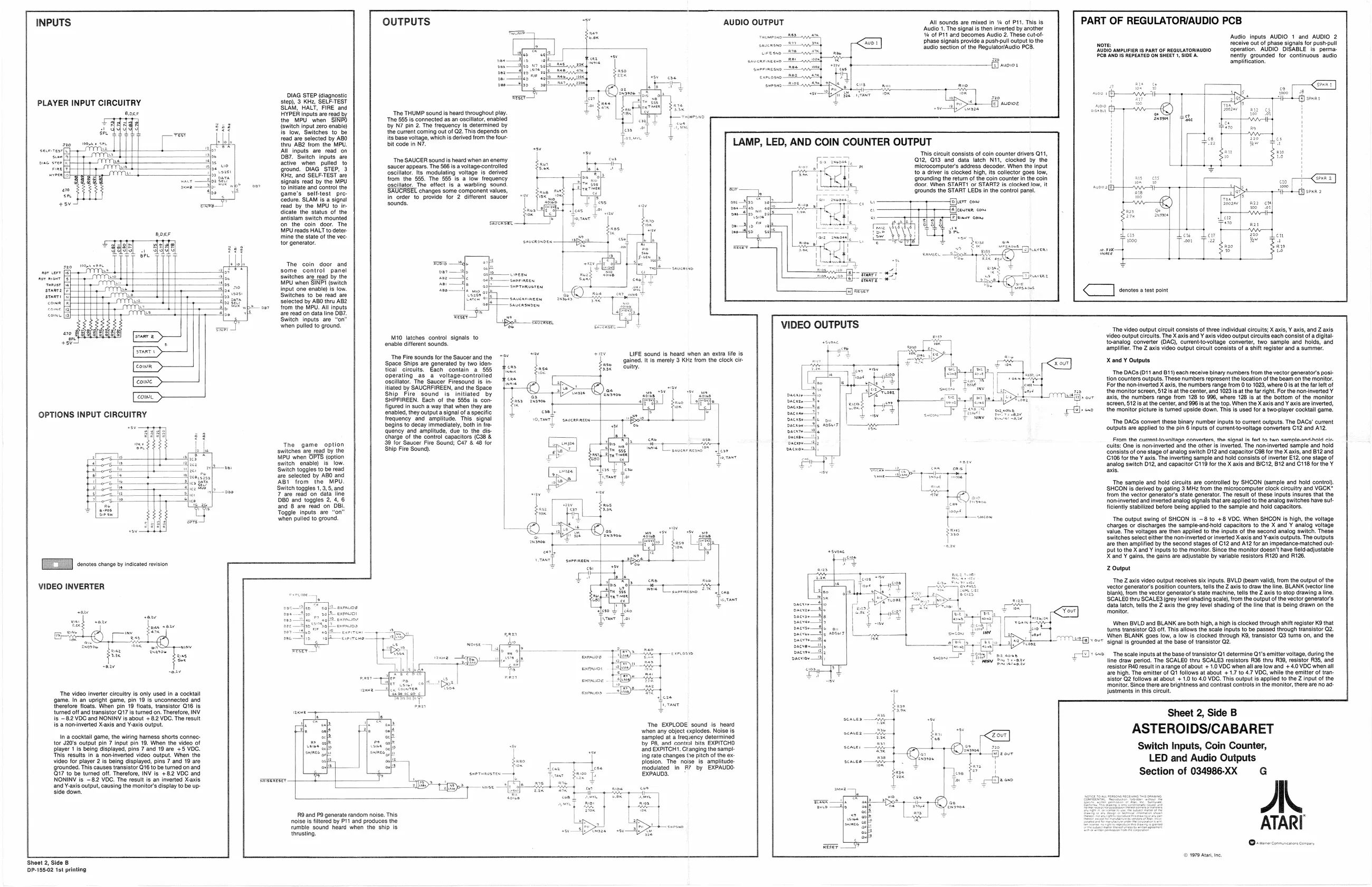
‘The video inverter circuitry is only used in a cocktail ‘game. In an upright game, pin 19 is unconnected and therefore floats. When pin 19 floats, transistor Q16 is turned off and transistor 217 is turned on. Therefore, INV Ig ~82 VOC and NONINV is about + 8.2 VOC. The result is anoninverted X-axis and Y-axis output.
Ina cocktail game, the wiring hamess shorts connector 420's output pin 7 input pin 19. When the video of blayer 1's being displayed, pins 7 and 19 are 4-5 VOC. This results in a noninverted video output. When the video or player 2 is being displayed, pins 7 and 19 are ‘grounded. This causes transistor Q16 to be turned on and 17 to be tuned off. Therefore, INV is +82 VDC and NONINV is ~82 VOC. The result is an inverted Xaxie and Y-axis output, causing the monitor's display to be up- ‘side down,
Sheet 2, Side B DP-185:02 1st printing DIAG STEP agnostic step) 3 Khe SeLPTEST SUAM, HALT, FIRE. and AYPER inputs ar ead by the MPU wnen “SINS {witch input ero enable) 's"iow, Switches tbo read are seleted by ABD {tru AB2 fom the MPU Bl impos are ead on Bar, Buit inputs. ae active when pulled “To grouns. "DIAG "STEP, '3 itor ane SELF-TEST are signals ead by tho MPU ce tanta and nto he Game's. selttest. pre Sedure: SLAM Is sign ‘ead by the MPU to in Gieate the status of the Sniisam switch mounted nthe. com. door The MUreade HALT to ceter. tine the state ofthe vee tor generator.
The coin door ané some control panel Switches are read by the MPU when SINPI (switch input one enable) is low. Switches to be read are Selected by ABO thru ABZ ver from the MPU. All inputs are read on data line O87. Switch inputs are “on” when pulled to ground,
‘The game option switches are read by the MPU when OPTS (option ‘switch enable). Is. low. ‘Switch toggles to be read ‘are selected by ABO and ABI from the MPU. ‘Switch toggles 1, 3,5, and 7 are read on data line DBO and tog and 8 are read on Toggle inputs are "on" when pulled to ground,
OUTPUTS
‘The THUMP sound is heard throughout play ‘The 585 is connected as an oscillator, enabled by N7 pin 2. The frequency Is determined by the current coming out of G2. This depends on its base voltage, which is derived from the fourbit code in N7.
‘The SAUCER sounds heard when an enemy
saucer appears. The 586 is a voltage-controlled
‘oscillator. Its modulating voltage is derived from the 555. The 555 Is a low frequency ‘scllator, ‘The effect Is a warbling sound, ‘changes some component values, in order to provide for 2 different saucer sounds.
M10 latches contro! signals to enable different sounds.
The Fire sounds for the Saucer andthe ~f¥ ‘Space Ships are genarated by two iden teal circuits, Each contain. a 555, operating a a voltage-controlied oscillator. The Saucer Firesound is in itlated by SAUCRFIREEN, and the Space Ship. Fire sound is initiated by SHPFIREEN. Each of the 5858 is con. figured in such a way that when they are tenabled, they output a signal ofa specific frequency and amplitude. This signal
SHPFIREEN. Each of the 5858 is con begins to decay immediately, both in fre
quency and amplitude, due to the dis charge of the control capacitors (C38 & 88 for Saucer Fire Sound; C47 & 48 for Ship Fire Sound)
RO and P9 generate random noise. This noise is filtered by P11 and produces the rumble sound heard when the ship is thrusting. AUDIO OUTPUT
LAMP, LED, AND COIN COUNTER OUTPUT
Sg 8 ir All sounds are mixed in 4 of P11. This is ‘Audio 1. The signal is then inverted by another i of P11 and becomes Audio 2. These cut-ofphase signals provide a push-pull output o the audio section of the Regulator/Audio PCB,
This circuit consists of coin counter drivers Q11, 012, O13 and data latch N11, clocked ay the microcomputer’s address decoder. When the input to a driver is clocked high, its collector goes low, ‘grounding the return of the coin counts ‘door. When START! or START? is. ‘grounds the START LEDs in the control panel
reser peers con PART OF REGULATOR/AUDIO PCB
‘Audio inputs AUDIO 1 and AUDIO 2 receive out of phase signals for push-pull ‘operation. AUDIO OISABLE is. perma: ently grounded for continuous. audio amplification. nore: ‘2UDIO AMPLIFIER Is PART OF REGULATORIAUDIO. C8 AND Is REPEATED ON SHEET 1, SIDEA.
LIFE sound Is heard when an extra life is ‘gainad. tis merely 3 KHz from the clock cir ‘uitry. an
onl:
yer
The EXPLODE sound is heard when any object explodes. Noise is ‘sampled at a frequency determined bby Pa and contfol bits EXPITCHO ‘and EXPITCHT. Ctanging the sampling rate changes tre pitch of the explosion. The noise is amplitude Modulated in R? by EXPAUDO- EXPAUDS, paease 4h
i
sear, —x 1
i “The video output circuit consists of three individual circuits; X axis, Y axis, and Z axis video output circuits. The X axis and Y axis video output circuits each consist ofa digital to-analog converter (DAC), current-lovoltage converter, two sample and holds, and amplifier. The Z axis video output circuit consists of a shift register and a summer. X and Y Outputs ‘The DACs (011 and B11) each receive binary numbers from the vector generator’s pos ton counters outputs, These numbers represent the location of the beam on the monitor. For the non-inverted X axis, the numbers range from Oto 1028, where Ois atthe far left of ‘the monitor screen, 512s atthe center, and 1023 s at the far right. For the non-inverted Y axis, the numbers range from 128 to 996, where 126 is at the bottom of the monitor ‘screen, $12: atthe center, and 996 is atthe top. When the X axis and Y axis are inverted, ‘the monitor picture is tured upside down. This is used for a two-player cocktail game. ‘The DACs convert these binary number inputs to current outputs. The DACs’ current ‘outputs are applied to the pin 6 inputs of current-tovoltage converters C12 and A12, From the current-towvaltage convertors, the signal ie fed ta two sample-and.nold os ‘outs: One Is norinverted and the other is inverted. The non-inverted sample and hol ‘consists of one stage of analog switch D12 and capacitor C98 for the X axis, and B12 and ‘C106 for the ¥ axis. The inverting sample and hold consists of inverter E12, one stage of ‘analog switch D12, and capacitor C119 for the X axis and B/G12, B12 and G118 for the Y axis.
‘The sample and hold circuits are controlled by SHCON (sample and hold contro). SHCON ie derived by gating 3 MHz from the microcomputer clock circuitry and VGCK" {rom the vector generator's state generator. The result of these inputs insures that the ‘nominvarted and inverted analog signals that are applied to the analog switches have sut ficiently stabilized before being applied to the sample and hold capacitors.
‘The output swing of SHCON is ~8 to +8 VDC. When SHOON is high, the voltage charges or discharges the sampleand-hold capacitors to the X and Y analog voltage value. The voltages are then applied to the inputs of the second analog switch. These ‘Switches select either the non-inverted or inverted Xaxis and Y-axis outputs. The outputs are then amplified by the second stages of C12 and At2 for an impedance-matched out- But to the Xand ¥ inputs to the monitor. Since the monitor doesn’t have field-adjustable X and ¥ gains, the gains are adjustable by variable resistors R120 and R126.
Z Output
‘The Z axis video output receives six inputs. BVLD (beam valid), rom the output of the vector generator’s position counters, tells the Z axis to draw the line. BLANK (vector line blank, rom the vector generator’s siate machine, tells the Z axis to stop drawing a lin 'SCALEO thru SCALES (grey level shading scale), from the output ofthe vector generators dala latch, tells the Z axis the grey level shading of the line that is being drawn on the ‘monitor. When BVLD and BLANK are both high, a high is clocked through shift register K9 that turns transistor Q3 off. This allows the scale inputs to be passed through transistor Q2. When BLANK goes low, a low Is clocked through K9, transistor Q3 tums on, and the signal is grounded at the base of transistor 02. ‘The scale inputs at the base of transistor Q1 determine Q1's emitter voltage, during the line draw period. The SCALEO thru SCALES resistors R96 thru R39, resistor R35, and resistor RA0 result in arange of about + 1.0 VOC when all are low and + 4.0 VDC when al, are high. The emitter of Qi follows at about + 1.7 to 4.7 VDC, while the emitter of transistor Q2 follows at about + 1.0 to 40 VDC. This output is applied to the Z input of the ‘monitor. Since there are brightness and conirast controls in the monitor, there are no ad justments in this circuit.
Sheet 2, Side B
ASTEROIDS/CABARET
Switch Inputs, Coin Counter, LED and Audio Outputs Section of 034986-XX G ae
© 1979 Ata ne,