Asteroids DP-143-5th-02B
Asteroids (rev 4) (Atari, 1979) · Drawing Package · 1 pages · original scan
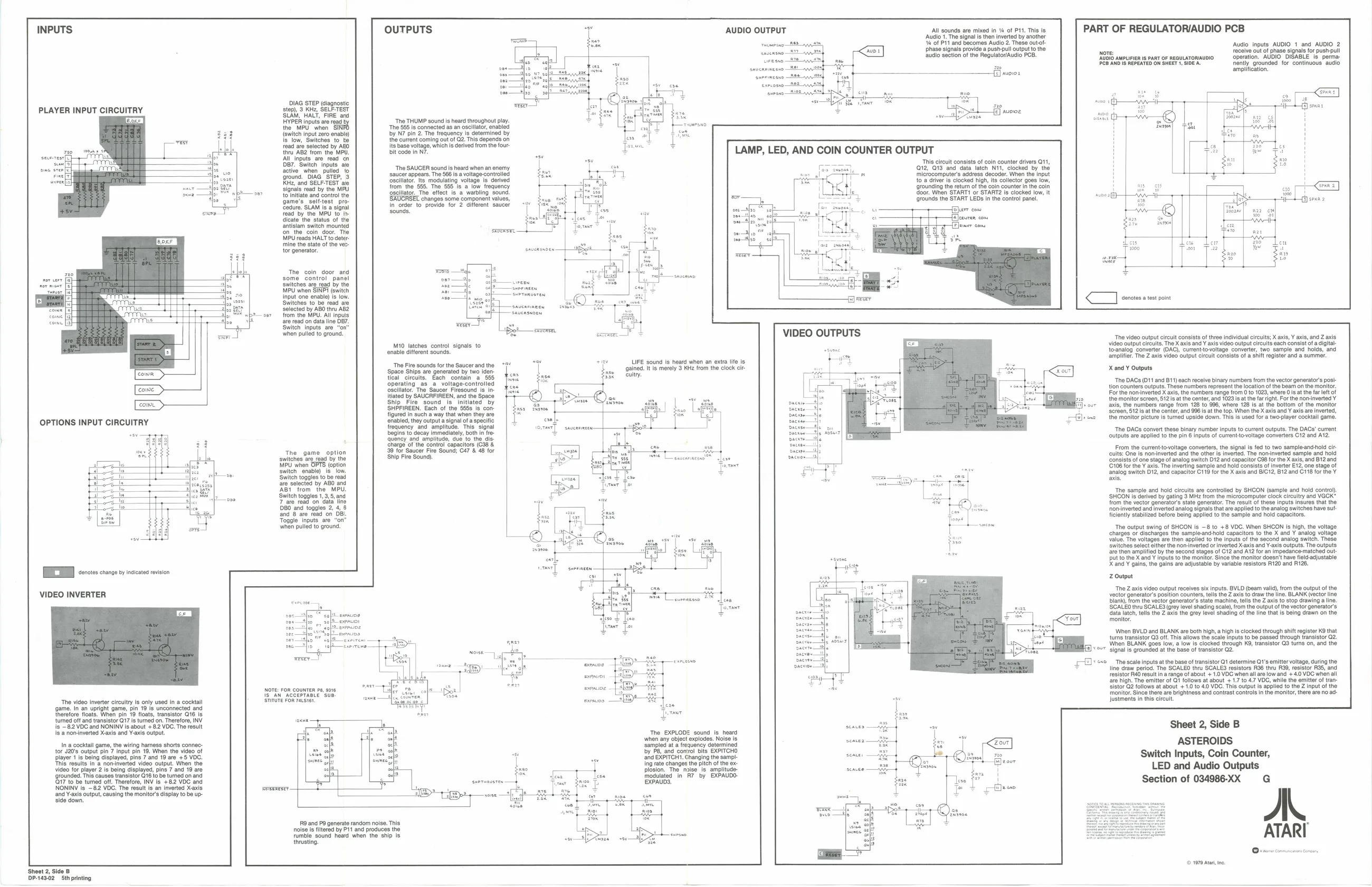
INPUTS OUTPUTS - AUDIO OUTPUT All sounds are mixed in 4 of P11. Tis is
‘Audio 1. The signal is then inverted by another ‘% of Pit and becomes Audio 2. These outotphase signals provide a push-pull output to the Audio section of the Regulator/Audio PCB.
PART OF REGULATORIAUDIO PCB
‘Audio inputs AUDIO 1 and AUDIO 2
nove! receive out of phase signals for push-pull
‘AUDIO AMPLIFIER Is PART OF REGULATORAUDIO Operation. AUDIO DISABLE Is perma:
PCB AND I6 REPEATED ON SHEET 1, SIDEA. nnently. grounded for continuous audio
amplification.
DIAG STEP (diagnostic PLAYER INPUT CIRCUITRY stop) 3 KH, SELECTEST Stab ati IRE ar puis are rad: the MPU when bird {switen input zero enadi) {S"tow, Switehos to, te Tead are selected by AED thru AB2 from the MPU. seanrenfeh TO AAI inputs are read on ool Br. Switeh inputs. ato
| one | sree | active when | plied “o |
Edin oF ground. DIAG STEP, 3 wreck ° Kia, and SELF-TEST a0 slate read by the MPU torniiate and Cont re game's. selltest pro Sedure, SLAM Is a signal ‘ead by the MPU to. Scat tho status of the Sntsiam switch mountes on, the. coin. door. The MU reads HALT toceter tine the state of the ves. for generator, ‘The 55 is connected as an oscillator, by N7 pin 2. The frequency is deter
the current coming out of G2. This depends on
its base voltage, which is derived from the four
bit code in N7. LED, AND COIN COUNTER OUTPUT
- This ceult consists of coin counter drivers Q11, ger) x2, O19 and data latch Ni", clocked. by the . ‘microcomputer’ address decoder. When the input toa drver ie clocked high, is collector goes low, {rounding th return ofthe coin counter nthe coin oor When START! or START? fe clocked tow, It ‘rounds tho START LEDS in the control panel, -——{a]ier™ com {Ejecsren coms ‘The SAUCER sounds heard when an enemy saucor appoars. The 866 is a voltage controlled ‘oscillator Its modulating voltage is derived from the 855. Tho. $55 sa low frequency escllator. The effect Isa warbling sound ‘SAUCRSEL changes some component values, in order to. provide for 2 diferent saucer sounds.
The coin door some control panel Switches are read by the MPU when SINPI (switch Input one enable) is 1ow. sos cre om oe at L
2 Seas ; sense oe ee = Sct aaa ar a ce. Se ee Loe sere ‘The video ouput cic consists of tee niu cc: X ai, nis, and ais M10 latches control signals to ‘video output cicuits. The X axis and ¥ axis video output circuits each consist of adigitaltenable different sounds. toanalog converter (AC), currentto-voltage converter, two sample and holds, and amplifier. The Z axis video output circuit consists of a shift register and a summer. ow LIFE sound is heard when an extra life is ‘gained. It is merely 3 KHz from the clock citcuit. ‘The Fire sounds for the Saucer and the “7 ‘Space Ships are generated by two identical circuits. Each contain a 555 operating a _a_voltage-controlied ‘oscillator. The Saucer Firesound is initiated by SAUCRFIREEN, and the Space
| ‘Ship | Fire | sound | is’ | initiated | by |
‘SHPFIREEN. Each of the 5858 Is configured in such a way that when they are ‘enabled, they output a signal of a specific. co], frequency and amplitude. This signal vow] savenn X and ¥ Outputs ‘The DACs (011 and B11) each recelve binary numbers from the vector generator's posi+ tion counters outputs. These numbers represent the location of the beam on the monitor. For the nom-inverted X axis, the numbers range from 0 to 1023, where 0 is atthe far left of the monitor screen, $121 atthe center, and 1023 is at the far right. For the non-inverted Y axis, the numbers range from 128 to 996, where 128 is at the bottom of the monitor ‘eréen, 51218 a the center, and 996 is atthe top. When the X axis and Y axis are inverted, the monitor picture is tumed upside down. This is used for a two-player cocktail game,
| —— ares by the | ES | ner) alyn taal | consists of one stage of analog switch D12 and capacitor C98 for the X axis, and B12 and | ||
| MR whee, | ieedon | 0 | 7 | C106 for the Y axis. The inverting sample and hold consists of inverter E12, one stage of | |
| Bieta ows | satchel ee | —. | O. | Tk | fnalog switch D12, and capacitor C119 forthe X axis and B/CT2, 812 and C118 for the Y |
The sample and hold circuits are controlled by SHCON (sample and hold control ‘Switch toggles 1, 3,5, and y (samp !) ental Sel guinea necro Stee ity aes VEER:
| Stew, | DBO and toggles 2, 4. 8 | [oy siibo0 | nor-inverted | and inverted analog signals tha are applied tothe analog switches have sut |
charges or discharges the samp ind+hold capacitors to the X and Y analog voltage a5 value, The voltages are then applied to the inputs of the second analog switch. These Switches select either the non-inverted or Inverted Xaxis and Y-axis outputs. The outputs bee are then amplified by the second stages of C12 and A12 for an impedance-matched out sven put to the X and ¥ inputs to the monitor. Since the monitor doesn't have field-adjustable Xand ¥ gains, the gains are adjustable by variable resistors R120 and R126.
Z Output HEDIS rescence en
VIDEO INVERTER ‘The Z axis video output receives six inputs. BVLD (beam vali), from the output of the vector generator’s position counters, tells the Z axis to draw the line. BLANK (vector ine blank, rom the vector generators state machine, tells the Z axis to stop drawing a line. ‘SCALED thru SCALES (grey level shading scale), from the output ofthe vector generator's data latch, tells the Z axis the grey level shading of the line that is being drawn on the ‘monitor. acu
When BVLD and BLANK are both high, a high Is clocked through shift register K9 that tums transistor Q3 off. This allows the scale inputs to be passed through transistor Q2. When BLANK goes low, a low Is clocked through K®, transistor Q3 turns on, and the signal is grounded at the base of transistor Q2. fete rene
Sy eorcesne omoe | ‘The scale inputs at the base of transistor Q1 determine Q1’s emitter voltage, during the line ‘draw period. The SCALEO thru SCALES resistors R36 thru R39, resistor R35, and
| e054 | PF | resistor R40 result in arange of about + 1.0 VDC when all are low and ++ 4.0 VOC when all |
| os | | | are high. The emitter of Gt follows at about + 1.7 to 4.7 VDC, while the emitter of tran- |
| = | aw | Sistor Q2 follows at about + 1.0 to 40 VOC. This output is applied to the Z input of the |
‘monitor. Since there are brightness and contrast controls in the monitor, there are no adow Justments in this circuit. eMs0t
| In. octal pane, he wing hava shart connec | Fe | Sampled ata requency determines | cits | ASTEROIDS | ||
| tor J20's output pin 7 input pin 1 | mn tt | Je0 of | - | P8, and control bits EXPITCHO | aw | 7 |
| Blt | is bon depayed in Yard V8 a8 VOC. | le | ahd BXTCHT Changing the samp | Pees | Switch Inputs, Coin Counter, | |
| fs results n'& nonsnvetted | vigeo output, | When the | ing | ate changes the pitch ofthe ex | i | |
| video for player? Is being displayed, pine 7 and 19 are | plsion. | Tho. aise. is amplitude. | xno | LED and Audio Outputs |
rounded, Ths causes transistor Gtotabe tuned on and frodulated in” RI” by EXPAUDO- Siro be tumed off Therefore, INV fs + 8.2 VOC and Section of 034986-XX G NONINV is ~82 VDC. The result is an inverted Xaxis and Y-axis output, causing the monitors display to be upside down.
9 and P9 generate random noise. This noise is filtered by P11 and produces the rumble sound heard when the ship is thrusting,
© 1979 Ata ne Sheet 2, Side B P-149-02 Sthprinting