Asteroids DP-143-7th-02B
Asteroids (rev 4) (Atari, 1979) · Drawing Package · 1 pages · original scan
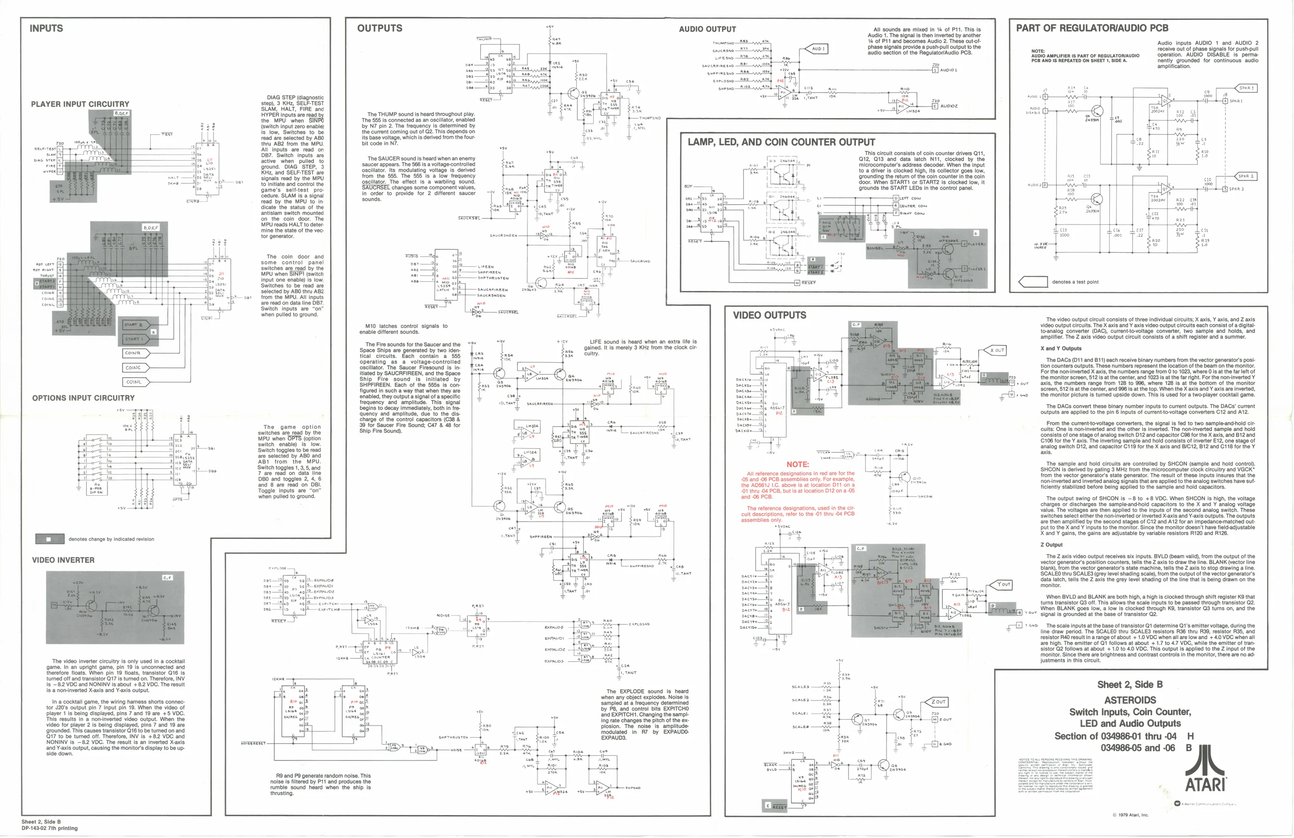
OUTPUTS 7 AUDIO OUTPUT All sounds are mixed in v4 of P11. This is PART OF REGULATOR/AUDIO PCB ‘Audio 1. The signal is then inverted by another '% of Pit and becomes Audio 2. These outot- ‘phase signals provide a pust-pull output othe ‘audio section of the Regulato/Audio PCB. ‘Audio inputs AUDIO 1 and AUDIO 2
Note recelve out of phase signals for pust-pull
[AUDIO AMPLIFIER Is PART OF REGULATORIAUOIO. operation. ‘AUDIO DISABLE is perma:
PCB AND Is REPEATED ON SHEET 1, SIDEA ently. grounded for continuous. audio
‘amplification.
oy 8 Kee Seu Test
- : PLAYER INPUT CIRCUITRY 20, St Fee
| ser | inputs | ae read |
the MPU when SINS {switen input zr enable) ‘Som, Suites tobe food ae selec by ABO ti ABZ rom tne MPU AA inputs "are ead on Bor."Bwiteh inputs are fcttve when pulled To ground. DIAG "STEP, '3 Kier and SeLr-TEST are Signals rad by the MPU = to initiate and control the Game's selttest pro. Sedore SCAM i 9 signa! read by the MPU to In Gieate tne status of the srtistam gwiten mount on. te com. door The WM reads HALT to deter. tine the state of te voe torgenerater. ‘The THUMP sound is heard throughout play. ‘The 585 is connected as an oscillator, enabled by N7 pin 2. The frequency is determined by the current coming out of G2. This depends on Its base voltage, which is derive from the fou bit code in N7.
LAMP, LED, AND COIN COUNTER OUTPUT
This circuit consata of coin counter drives Q11, freer 12, 039 and. deta latch Ni, clocked. by the " ‘microcomputers address decoder. When the Input {oa driver is clocked high ts collector goes low, ‘rounding the retum ofthe coin counter nth coin oor When START! or START® fe clocked low, It ‘rounds the START LEDS in the control pana. air com {E}eauren com TT ie ons Ty ie
‘The SAUCER sound is heard when an enemy
saucer appears, The 566 Is a voltage-controlled
‘oscillator. Its modulating voltage is derived from the §§5. The 555 Is a low frequency oscillator, The effect is a warbling sound. 'SAUCRSEL changes some component values, in order to provide for 2 different saucer sounds.
The coin door ang
| some | control. | panel |
Switches are read by the MPU when SIND (switch
| Input one enable) is low, | mye | ‘sueranveren | ||
| Switches to be read are | So | ar | ||
| ‘elected by ABO thru ABZ | Ure? | aE] | —saueanneen | — anitis |
oer from the MPU. All inputs Shuensnoen are read on data line OI Switch inputs are “on” wo
| when | pulled to | ground. | |
| lll | VIDEO OUTPUTS | Tne vdeo output cite conse of three individual cet; X a, | al, and Z als |
Mio latches contol signals to . video output circuits. The Xaxis and Y axis video output cult each consist of digital
| enable different sounds. | — | ‘to-analog converter (DAC), current-to-voltage converter, two sample and holds, and |
Hey amplifier. The Z axis Video output crelt consists ofa shift rgistor and a summer ow +17 LIFE sound is heard when an extra life Is : ‘The Fire sounds for the Saucer and the 7 ‘Space Ships are generated by two Iden teal circults. Each contain a 555
| operating a | _a | voltage-controlied |
‘oscillator. The Saucer Firesound is initlated by SAUCRFIREEN, and the Space
| Ship | Fire sound | is’ initiated | by |
SHPFIREEN. Each of the 5858 Is con. ‘gained. It is merely 3 KHz from the clock cir ccuitry. X and ¥ Outputs ‘The DACs (011 and B11) each receive binary numbers from the vector generator’s posi+ ton counters outputs. These numbers represent the location of the beam on the monitor. For the nominverted X axis, the numbers range from 0 to 1023, where Os at the far left of the monitor screen, 512s atthe center, and 1023 is atthe far right. For the nonvinverted Y_ ‘axis, the numbers range from 128 to 896, where 128 is at the bottom of the monitor
| Seances | em | oer | Sse meee | aie | tees na me | ann Ls a |
| eetineen | con amie | aee | aa | Sresshaberamsumanaene eterna | aera | |
| OPTIONS INPUT CIRCUITRY | merrmiesageee | | | | | xo |
3] ‘The DACs convert these binary number inputs to curent outputs. The DACs’ current
| ‘begins to decay immediately, both in fre | = | ‘outputs are applied to the pin 6 Inputs of current-tovoltage converters C12 and A12. |
quency and amplitude, due to the dis EE ) |
| Fy | Sharge of the contol capacitors (628 & | seen] | |||||||||
| ge | a | " | se | eer | From the | currenttovoltage | converter, the signal i fe to two sampleandhold ci- | ||||
| i | A | The | game | option | Ser seen 9 Sous CF | tor | pn | ee | Ser | cults: | One is norinverted and the other is inverted The nor inverted sample and hold |
| | | sortase ag By the | sa | ara | onsiets | of one stage of analog switch O12 and capacitor Gab forthe X axis, and B1Zand | ||||||
| ae | PU won OPTS (op | i | {G08 forthe | axl. The inverting sample and noid consists of nvertr E12 one stage of | |||||||
| ae | Bt | has | Switch enable) | Is | Tow | I | Snalog switch O12, and capacitor G11 for the X ani and BCT, B12 and C118 for Ne Y | ||||
| 7 | Switch togges to be read | 4. | vom | aus. | |||||||
| as Ae | te | are selected by ABO and | yee) | ||||||||
| —— | fog | Bt | from the | MPU. | NOTE: | ‘The sample and hold circults are controled by SHCON (sample and hold conto). | |||||
| Hoe | | | Sten toggles 13:5 and | ‘SHON is Gord by pating 9 MHz from the microcomputer clock cleuty ano VECK | ||||||||
| an | ie | rae ead oni ta | glance cearane irda | rhe | from the vector generators state generator The result of hese Inputs insure thatthe | ||||||
| te | sseomblles | only. | For | example, | H | f | |||||
| : | 60 ane | Togas | 2 4,6 | ‘5 and 98 PCB assembles ony For oamote, | noninverted andinvertd analog signals tat are applied to the analog switches have su. | ||||||
| Som | se | fa | Soman OF | ficiently stabilized before being applied to the sample and hold capacitors. |
and -06 PCB, Toggle inputs are. “on’
| when pulled to ground. | scone | ‘The output swing of SHCON is -8 to +8 VDC. When SHCON is high, the voltage: |
charges or discharges the sample-and+hold capacitors to the X and Y analog voltage ‘The reference designations, used inthe ci value. The voltages are then applied to the inputs of the second analog switch. These
| cuit descriptions, refer to the 01 thru | ‘switches select either | the nominverted or inverted X-axis and Y-axis outputs. The outputs, |
| assemblies only | are then amplified by the | second stages of C12 and A12 for an impedance-matched out. |
Svone ‘put to the X and ¥ inputs to the monitor. Since the monitor doesn't have fiekéadjustable ee X and ¥ gains, the gains are adjustable by variable resistors A120 and 128. Z Output
‘The Z axis video output receives six inputs. BVLD (beam vali), from the output of the vector generator's position counters, tells the Z axis to draw the line. BLANK (vector line ‘blank, rom the vector generator’ siate machine, tells the Z axis to stop drawing a line. ‘SCALED thru SCALES (grey level shading scale, from the output of the vector generator’s data latch, tells the Z axis the grey level shading of the line that is being drawn ont ‘monitor. DEED cscs nso ston
VIDEO INVERTER
ql \When BVLD and BLANK are both high, a highs clocked trough shit repstor KB that adtus ‘tums transistor Q3 off. This allows the scale inputs to be passed through transistor Q2. oH Viton BLANK goes Towa low a clocked tgugh KB, wansloor G3 tun on and the Signal fe groundod at base of anastor 2, ‘The scale inputs at the base of transistor Q1 determine Q1's emitter voltage, during the line draw period. The SCALEO thru SCALES resistors R36 thru R39, resistor R35, and resistor R40 resuit in arange of about + 1.0 VDC when all are low and '+ 40 VDC when all are high. The emitter of Q1 follows at about + 1.7 to 4,7 VDC, while the emitter of transistor Q2 follows at about + 1.0 to 40 VDC. This output Is applied to the Z input of the ‘monitor. Since there are brightness and contrast controls inthe monitor, there are no adoy justments in this circuit. ‘The video inverter circuitry is only used in a cocktail game. In an upright game, pin 19 is unconnected and therefore floats. When pin 19 floats, transistor Q16 Is. turned off and transistor Q17 is turned on. Therefore, INV
Q17 to be turned off. Therefore, INV Is +82 VOC and
| Is | "62 VoCand NONINY Is about +82VDG-The result | sen | Sheet 2, | Side |
is a noninverted Xaxis and Y-axis output. ‘The EXPLODE sound Is heard 2, Side B
| Ina cocktail game, the wiring harness shorts connec: | balsa | lencengert tld] | seater | bd | sont | ASTEROIDS |
torv20e output pin 7 input pin 19, When te video of Sy Paand contol be EXETTOND
| lay 1's being aepiaved, pin 7 and 10 ae + 6 VOC. | “e | ead EXATTCHT, Changing the sampl- | seauer | roel | 288 | Switch Inputs, Coin Counter, |
| is results in a non-inver | tput. When | ~ | ch of the ex- | jeour | ||
| video for player 2 is being daplyed, pins 7 and 19 ae | Hostoe. tna noite is amplitude. | ecaces | 7 | LED and Audio Outputs | ||
| ‘rounded Ths causes | transis | ured | on an | Bes. eee | SS | ae |
| by | a | Section of 034986-01 thru -04 | H |
EXPAUD3.
| NONINV is ~82 VOC. The result Is an inverted Xaxts | : | : | oes | |||
| ‘and Y-axis output, causing the monitors display to be up- | DIED | = | — | a | 034986-05 and -06 | B |
| [RO and P9 generate random noise. This | wo SE | zl | + | Stesce | ||
| noise is fitered by Pit and produces the | site | he | % |
ATARI rumble sound heard when the ship is ‘thrusting.
(© 1979 Ata, ne. Sheet 2, Side B DP-14302 7th printing